EP1703255A2 - Procédé et dispositif destiné au calcul d'une limite de vitesse supérieure pour un véhicule - Google Patents
Procédé et dispositif destiné au calcul d'une limite de vitesse supérieure pour un véhicule Download PDFInfo
- Publication number
- EP1703255A2 EP1703255A2 EP06110387A EP06110387A EP1703255A2 EP 1703255 A2 EP1703255 A2 EP 1703255A2 EP 06110387 A EP06110387 A EP 06110387A EP 06110387 A EP06110387 A EP 06110387A EP 1703255 A2 EP1703255 A2 EP 1703255A2
- Authority
- EP
- European Patent Office
- Prior art keywords
- vehicle
- route
- speed
- predetermined
- starting point
- Prior art date
- Legal status (The legal status is an assumption and is not a legal conclusion. Google has not performed a legal analysis and makes no representation as to the accuracy of the status listed.)
- Withdrawn
Links
Images

Classifications
-
- G—PHYSICS
- G01—MEASURING; TESTING
- G01P—MEASURING LINEAR OR ANGULAR SPEED, ACCELERATION, DECELERATION, OR SHOCK; INDICATING PRESENCE, ABSENCE, OR DIRECTION, OF MOVEMENT
- G01P1/00—Details of instruments
- G01P1/07—Indicating devices, e.g. for remote indication
- G01P1/08—Arrangements of scales, pointers, lamps or acoustic indicators, e.g. in automobile speedometers
- G01P1/10—Arrangements of scales, pointers, lamps or acoustic indicators, e.g. in automobile speedometers for indicating predetermined speeds
- G01P1/103—Arrangements of scales, pointers, lamps or acoustic indicators, e.g. in automobile speedometers for indicating predetermined speeds by comparing the value of the measured signal with one or several reference values
-
- G—PHYSICS
- G01—MEASURING; TESTING
- G01C—MEASURING DISTANCES, LEVELS OR BEARINGS; SURVEYING; NAVIGATION; GYROSCOPIC INSTRUMENTS; PHOTOGRAMMETRY OR VIDEOGRAMMETRY
- G01C21/00—Navigation; Navigational instruments not provided for in groups G01C1/00 - G01C19/00
- G01C21/26—Navigation; Navigational instruments not provided for in groups G01C1/00 - G01C19/00 specially adapted for navigation in a road network
-
- G—PHYSICS
- G08—SIGNALLING
- G08G—TRAFFIC CONTROL SYSTEMS
- G08G1/00—Traffic control systems for road vehicles
- G08G1/01—Detecting movement of traffic to be counted or controlled
- G08G1/052—Detecting movement of traffic to be counted or controlled with provision for determining speed or overspeed
Definitions
- the invention relates to a method and a device for determining an upper speed limit for a vehicle, within a predetermined route, for which a maximum speed is predetermined.
- the route may be a section on one of these roads.
- a speed of the vehicle within the route may be determined by means of a speed control external to the vehicle. For example, with a radar control, the current speed of the vehicle is determined.
- the average speed of the vehicle with which the entire route is covered by the vehicle can be determined in different ways by a detection device external to the vehicle.
- the vehicle may be registered at a starting point of the route and at a destination point of the route.
- a total period of time in which the route was traveled by the vehicle can be measured.
- the average speed with which the vehicle has crossed the route results from the ratio of the length of the route to the total time required. If the average speed is above the permissible maximum speed and above a country - specific measuring tolerance, the driver of the vehicle must, depending on the height of the vehicle Average speed at least one fine to be paid.
- the object of the invention is to provide a method and a device which allows a driver a favorable traffic behavior within a predetermined route.
- the invention is characterized by a method and a corresponding device for determining an upper speed limit for a vehicle, in which a position of the vehicle is detected within a predetermined route. Further, a period of time is detected in which the vehicle comes from a starting point of the route to the position.
- the upper speed limit for the vehicle is determined depending on the starting point, a predetermined destination point, the position of the vehicle and the time duration.
- the upper speed limit is determined as an average speed at which the vehicle can travel from the position of the vehicle to the destination point of the route without exceeding, on average, a given maximum speed for the entire route.
- the method may do so contribute, just one To avoid loss of time by unnecessarily slow driving and to make the driving behavior of a driver ecologically and / or economically.
- the procedure can help to avoid a fine because of excessive speed.
- the position of the vehicle is determined within the route with a positioning system. This allows a very accurate positioning of the vehicle and is very comfortable for the driver.
- the position of the vehicle within the route is determined by a distance measurement relative to the starting point of the route. In this way, the position of the vehicle can be easily determined.
- the maximum speed (HG) is increased by a predetermined measurement tolerance of a speed control.
- This measurement tolerance can be country-specific, for example. The driver is thus enabled to adapt his driving behavior to the measurement tolerance.
- the starting point, the destination point and / or the route and / or the predetermined maximum speed are called up by an information device external to the vehicle.
- the starting point and the destination point can be called up and / or the route.
- the default top speed for the route can also be accessed. Retrieving information from one relating to the vehicle External information device can easily increase the comfort of the driver.
- the vehicle comprises an image recognition device that is coupled to a vehicle camera.
- a traffic sign is detected on the route, which includes the predetermined maximum speed.
- the predetermined maximum speed is determined on the basis of the detected traffic sign by comparison with stored image data. The automatic determination of the given maximum speed can simply increase the comfort for the driver.
- the device comprises an input unit by means of which the starting point, the destination point and / or the route and / or the predefined maximum speed and / or the measuring tolerance can be entered. If a modified maximum speed is set at the beginning of the route, the input unit makes it possible to enter the change of the maximum speed into the device. The same applies to the case where the starting point or the destination point of the given route has been changed.
- the device comprises the image recognition device, which is coupled to the vehicle camera.
- the automatic determination of the given maximum speed can simply increase the comfort for the driver.
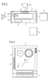
- a starting point SP and a destination point ZP of a route R specify a length L of the route R (FIG. 1).
- the route may be a section on a highway or other road.
- a vehicle 2 preferably a motor vehicle.
- the vehicle 2 has traveled a portion A of the route R from the starting point SP to the position P in a period of time Z.
- a maximum permissible speed HG is given. This may for example be a speed limit due to a construction site, but it may also be a different speed limit.
- the vehicle 2 is allowed to cover the route R on average at most with the maximum permissible speed HG. Otherwise a driver of vehicle 2 must pay a fine.
- the driver has several options to respond to the maximum permissible speed HG.
- a first possibility is to continuously monitor a current speed of the vehicle 2 from the starting point SP of the route R up to the destination point ZP. This will distract the driver. This contributes to an increased accident risk.
- a second possibility for the driver to respond to the maximum speed HG is to drive so slowly that the maximum speed HG is guaranteed not exceeded. This can contribute to a slowing down of the entire traffic flow and congestion on the route R.
- a device 3 for determining an upper speed limit OS for a vehicle 2 comprises a storage unit 4, a location system 6 and a measurement unit 8.
- the device 3 makes it possible for the driver at any time within the route R to know how he can drive fast without having exceeded the maximum permissible speed HG at the destination ZP on average and without hindering the traffic on the route R.
- the storage unit 4 the starting point SP, the destination point ZP, the route R and the length L of the route R, and the maximum permissible speed HG for the route R are stored.
- the location system 6 comprises an odometer with which the position P within the route R is determined. With the measuring unit 8, the time period Z is determined, in which the vehicle 2 passes from the starting point SP to the position P.
- the acquired data are combined in an evaluation unit 10, which then determines the upper speed limit OS.
- An output unit 12 outputs the upper speed limit OS off.
- the output unit 12 comprises a loudspeaker 16 and / or an optical display 18.
- a pleasant sounding short melody is preferably output via the loudspeaker 16 when the upper speed limit OS is exceeded.
- the visual display 18 includes the upper speed limit OS, which is preferably similar to a directional speed on the highway.
- the device 3 has a mobile radio device 20. By means of the mobile radio device 20, the starting point SP, the destination point ZP and / or the route R and / or the predetermined maximum speed HG can be retrieved, received and updated from an information source external to the vehicle.
- the output unit 12 may also be coupled to a vibration alarm, for example on a steering wheel of the vehicle 2.
- the permissible maximum speed HG is indicated by a traffic sign at least at the starting point SP of the route R.
- the traffic sign can be detected.
- an image recognition device 24 which is coupled to the vehicle camera 22, the maximum permissible speed can be determined by comparing the detected traffic sign with stored image data.
- the image data include, for example, all possible speed restrictions of one, preferably several countries.
- the image data may be stored in the storage unit 4 and / or retrieved from an information source external to the vehicle 2.
- a navigation system (FIG. 3) comprises the device 3.
- the visual display 18 preferably comprises a clear screen. On the screen is preferred the upper speed limit OS, the maximum speed limit HG, as well as the route R with the starting point SP and the destination point ZP, as well as the position P of the vehicle 2 shown. It is also possible to represent a length N of a remainder section B (FIG. 1) which extends from the position P to the destination point ZP. In addition, it can be signaled if a minimum period of time is exceeded in which the route R should at least be traversed. The minimum period of time results from the ratio of the length L of the route R to the maximum permissible speed HG.
- the navigation system preferably has a satellite receiver 26 and a loudspeaker 16.
- the navigation system has an input unit 14, which makes it possible to input the starting point SP, the destination point ZP and / or the route R and / or the predetermined maximum speed HG.
- the input unit 14 may comprise, for example, a touch screen or a keyboard.
- the navigation system comprises the memory unit 4, which comprises an integrated memory and / or a receiving slot for a removable data carrier.
- the removable medium may be, for example, a CD-ROM or a flash memory card.
- the memory unit 4 can also be designed without integrated memory.
- a road map is preferably stored on the integrated memory and / or the removable data carrier.
- the road map includes the route R with the starting point SP and the destination point ZP.
- the maximum speed HG can also be stored on the storage unit 4.
- the input unit may include a microphone and speech recognition software.
- a program is started in the device 3, which executes the steps S1 to S8 (FIG. 4).
- the program is stored in the storage unit 4. It is also possible to store the current status of the process in the memory unit 4, if, for example, during a break or when refueling the vehicle (2) is turned off, so that the method can continue to be processed when driving on.
- a step S1 the program is started.
- a step S2 is executed in which the length L of the route R is determined based on the route of the route R, the start point SP, and the destination point ZP.
- the position P of the vehicle 2 within the route R and the length M of the subsection A are determined.
- the length M may be determined, for example, depending on the route R stored in the storage unit 4 and the position P.
- the time period Z is determined in which the vehicle 2 has arrived from the starting point SP to the position P.
- the upper speed limit OS is determined by the evaluation unit 10 as a function of the length M of the subsection A, the time duration Z, the length L of the route R and the permissible maximum speed HG, preferably correspondingly the calculation rule specified in step S6.
- the steps S2, S3 and S4 can be arbitrarily reversed in their order.
- a step S7 it is checked whether M ⁇ L or the vehicle 2 has not yet passed the destination point ZP. As long as M ⁇ L, steps S3 to S7 are repeated. Otherwise, the program is ended in a step S10. If, during execution of step S5, the minimum time duration has been exceeded, the driver is informed in a step S8 that he is displaying the remaining portion B at any desired speed can go back.
- a step S9 it is checked whether M ⁇ L, or the vehicle 2 has not yet passed the target point ZP. As long as M ⁇ L, the step S9 is repeated and the driver indicated that he can cover the remaining portion B at any speed.
- the program can also be executed without steps S8 and / or S9. Once M ⁇ L, the program is ended in a step S10.
- the calculation of the upper speed limit OS can also be done in other ways.
- the length M of the section A can be detected by a range finder, in particular by an odometer.
- the time Z may also be determined by specifying any suitable time intervals and counting the time intervals that are passed until the vehicle is at position P.
- the upper speed limit OS can also be determined by determining the length N of the remainder section B (FIG. 1) and by determining a remaining time T as the difference between the minimum time duration in which the entire route R should at least be traveled through and the time duration Z , The remaining time T should at least require the vehicle 2 in order to get from the position P to the destination point ZP.
- the upper speed limit then results from the ratio of the length N of the remaining section B to the remaining time T.
- a country-specific predetermined measuring tolerance can also be taken into account in a speed control. This increases the permissible maximum speed HG by the measuring tolerance and enters the calculation of the upper speed limit OS with a higher value.
- the upper speed limit OS can then be displayed with and / or without consideration of the measurement tolerance.
- the measuring tolerance can be input via the input unit 14 and / or stored in the memory unit 4 and / or retrieved from an information source external to the vehicle 2.
- the upper speed limit OS can be calculated by any other combination of the given sizes, which leads to the same result.
- the device 3 can be designed as an independent device. However, the device 3 can also be integrated in any other electronic device, for example in a handheld computer, a laptop, a car radio or an on-board computer.
- the device 3 can also be equipped without a mobile radio device 20.
- the device 3 may be equipped with the satellite receiver 26.
- the navigation system can also be equipped without satellite receiver 26 and / or with the mobile radio device 20.
Landscapes
- Engineering & Computer Science (AREA)
- Radar, Positioning & Navigation (AREA)
- Remote Sensing (AREA)
- Physics & Mathematics (AREA)
- General Physics & Mathematics (AREA)
- Automation & Control Theory (AREA)
- Navigation (AREA)
- Traffic Control Systems (AREA)
- Electric Propulsion And Braking For Vehicles (AREA)
- Control Of Vehicle Engines Or Engines For Specific Uses (AREA)
- Controls For Constant Speed Travelling (AREA)
Applications Claiming Priority (1)
| Application Number | Priority Date | Filing Date | Title |
|---|---|---|---|
| DE200510012131 DE102005012131B3 (de) | 2005-03-16 | 2005-03-16 | Verfahren und Vorrichtung zum Ermitteln einer oberen Geschwindigkeitsschranke für ein Fahrzeug |
Publications (2)
| Publication Number | Publication Date |
|---|---|
| EP1703255A2 true EP1703255A2 (fr) | 2006-09-20 |
| EP1703255A3 EP1703255A3 (fr) | 2008-07-02 |
Family
ID=36570676
Family Applications (1)
| Application Number | Title | Priority Date | Filing Date |
|---|---|---|---|
| EP06110387A Withdrawn EP1703255A3 (fr) | 2005-03-16 | 2006-02-24 | Procédé et dispositif destiné au calcul d'une limite de vitesse supérieure pour un véhicule |
Country Status (2)
| Country | Link |
|---|---|
| EP (1) | EP1703255A3 (fr) |
| DE (1) | DE102005012131B3 (fr) |
Cited By (4)
| Publication number | Priority date | Publication date | Assignee | Title |
|---|---|---|---|---|
| GB2479650A (en) * | 2010-04-15 | 2011-10-19 | Bosch Gmbh Robert | Navigation device determining a maximum possible speed of a vehicle within a remaining region of a speed measurement section |
| WO2013139602A1 (fr) | 2012-03-19 | 2013-09-26 | Basf Se | Dispersions aqueuses durcissables par rayonnement |
| US9193888B2 (en) | 2012-03-19 | 2015-11-24 | Basf Se | Radiation-curable aqueous dispersions |
| CN105416171A (zh) * | 2015-11-30 | 2016-03-23 | 上海斐讯数据通信技术有限公司 | 汽车刹车提醒系统、方法、及报警系统 |
Family Cites Families (6)
| Publication number | Priority date | Publication date | Assignee | Title |
|---|---|---|---|---|
| DE19829162A1 (de) * | 1998-06-30 | 2000-01-05 | Erwin Dietz | Verwendung einer elektronischen Kamera und einer mit ihr zusammenarbeitenden Bilderkennungseinrichtung in einem Automobil zum Erkennen von Verkehrszeichen |
| DE19933639A1 (de) * | 1999-07-17 | 2001-01-18 | Bosch Gmbh Robert | Verfahren zur Berechnung einer Route von einem Start- zu einem Zielort |
| GB9924554D0 (en) * | 1999-10-19 | 1999-12-22 | Jfdi Engineering Ltd | Improvements in or relating to vehicle navigation |
| US6265989B1 (en) * | 2000-06-17 | 2001-07-24 | Richard Taylor | GPS enabled speeding detector |
| US6573827B1 (en) * | 2000-11-14 | 2003-06-03 | Detroit Diesel Corporation | System and method of detecting vehicle speed limiting system tampering |
| NL1025095C2 (nl) * | 2003-12-22 | 2005-06-23 | Stichting Noble House | Systeem voor het regelen van de snelheid van een voertuig. |
-
2005
- 2005-03-16 DE DE200510012131 patent/DE102005012131B3/de not_active Expired - Fee Related
-
2006
- 2006-02-24 EP EP06110387A patent/EP1703255A3/fr not_active Withdrawn
Cited By (5)
| Publication number | Priority date | Publication date | Assignee | Title |
|---|---|---|---|---|
| GB2479650A (en) * | 2010-04-15 | 2011-10-19 | Bosch Gmbh Robert | Navigation device determining a maximum possible speed of a vehicle within a remaining region of a speed measurement section |
| GB2479650B (en) * | 2010-04-15 | 2012-06-27 | Bosch Gmbh Robert | Method and navigation device for determining a maximum possible remaining section speed of a vehicle |
| WO2013139602A1 (fr) | 2012-03-19 | 2013-09-26 | Basf Se | Dispersions aqueuses durcissables par rayonnement |
| US9193888B2 (en) | 2012-03-19 | 2015-11-24 | Basf Se | Radiation-curable aqueous dispersions |
| CN105416171A (zh) * | 2015-11-30 | 2016-03-23 | 上海斐讯数据通信技术有限公司 | 汽车刹车提醒系统、方法、及报警系统 |
Also Published As
| Publication number | Publication date |
|---|---|
| EP1703255A3 (fr) | 2008-07-02 |
| DE102005012131B3 (de) | 2006-08-03 |
Similar Documents
| Publication | Publication Date | Title |
|---|---|---|
| DE112015004218B4 (de) | Fahrassistenzvorrichtung | |
| DE102007062680B4 (de) | Verkehrsstaugradbestimmungsvorrichtung, Verkehrsstaugradmeldevorrichtung und Programm | |
| EP2116984B1 (fr) | Système d'assistance destiné au soutien du conducteur dans des véhicules | |
| DE102007006870B4 (de) | Kartenbewertungssystem und Kartenbewertungsverfahren | |
| EP1636550A1 (fr) | Systeme de navigation a informations sur les voies de circulation | |
| DE10260678A1 (de) | Verfahren zum Senden von Kartendaten sowie Kartenanzeigegerät und -system | |
| DE202013006466U1 (de) | Computerprogrammprodukt und Fahrerassistenzsystem für einFahrzeug | |
| WO2006037360A1 (fr) | Systeme pour informer un conducteur de la possibilite d'effectuer des depassements | |
| DE102012013376A1 (de) | Fahrerassistenzsystem | |
| DE102019102924A1 (de) | Verfahren, Vorrichtung, Computerprogramm und Computerprogrammprodukt zum Betreiben einer Fahrerassistenzfunktion eines Fahrzeuges | |
| WO2001057476A1 (fr) | Systeme de navigation et procede de configuration d'un systeme de navigation | |
| DE102016209240A1 (de) | Fahrassistenzvorrichtung und fahrassistenzverfahren | |
| EP1147375A1 (fr) | Procede pour guider le pilote d'un vehicule entre au moins un point de depart et au moins un point de destination | |
| DE102011077941A1 (de) | Verfahren und Vorrichtung zur Bestimmung einer Tauglichkeit einer Route | |
| DE10361407A1 (de) | Navigationssystem und Programm und Speicherträger zur Verwendung in diesem | |
| EP1519339A1 (fr) | Dispositif pour délivrer des codes de la route et système pour l'information des conducteurs | |
| DE102005018138A1 (de) | Kraftfahrzeugvorrichtung mit einer Recheneinheit | |
| DE102009053982A1 (de) | System zur Berechnung einer verbrauchsoptimierten Route eines Kraftfahrzeugs, Kraftfahrzeug mit einem entsprechenden System sowie Verfahren zur Berechnung einer verbrauchsoptimierten Route | |
| DE10258161B4 (de) | Fahrzeugnavigationssystem und diesbezügliches Verfahren | |
| DE102021206413A1 (de) | Verfahren zum Bestimmen einer aktuell befahrbaren Trajektorie für ein zumindest teilweise assistiert betriebenes Kraftfahrzeug, sowie Assistenzsystem | |
| EP1130560B1 (fr) | Dispositif et procédé pour fonctionnement d'un véhicule | |
| DE102018216122A1 (de) | Fahrerinformationssystem, eingerichtet zur Informations-Ausgabe an einen Fahrzeugführer in Abhängigkeit eines Regelverstoßes gegen eine Verkehrsregel beim Führen des Fahrzeugs und Fahrerinformationsverfahren dazu | |
| DE102007004453A1 (de) | Verfahren und Vorrichtung zur Wiedergabe einer Verkehrszeicheninformation in einem Fahrzeug | |
| EP2654027B1 (fr) | Procédé d'émission d'un avertissement avant un dépassement | |
| EP1654139A1 (fr) | Systeme d'assistance a la conduite avec dispositif de verrouillage de fonction |
Legal Events
| Date | Code | Title | Description |
|---|---|---|---|
| PUAI | Public reference made under article 153(3) epc to a published international application that has entered the european phase |
Free format text: ORIGINAL CODE: 0009012 |
|
| AK | Designated contracting states |
Kind code of ref document: A2 Designated state(s): AT BE BG CH CY CZ DE DK EE ES FI FR GB GR HU IE IS IT LI LT LU LV MC NL PL PT RO SE SI SK TR |
|
| AX | Request for extension of the european patent |
Extension state: AL BA HR MK YU |
|
| RAP1 | Party data changed (applicant data changed or rights of an application transferred) |
Owner name: CONTINENTAL AUTOMOTIVE GMBH |
|
| PUAL | Search report despatched |
Free format text: ORIGINAL CODE: 0009013 |
|
| AK | Designated contracting states |
Kind code of ref document: A3 Designated state(s): AT BE BG CH CY CZ DE DK EE ES FI FR GB GR HU IE IS IT LI LT LU LV MC NL PL PT RO SE SI SK TR |
|
| AX | Request for extension of the european patent |
Extension state: AL BA HR MK YU |
|
| AKX | Designation fees paid | ||
| REG | Reference to a national code |
Ref country code: DE Ref legal event code: 8566 |
|
| STAA | Information on the status of an ep patent application or granted ep patent |
Free format text: STATUS: THE APPLICATION IS DEEMED TO BE WITHDRAWN |
|
| 18D | Application deemed to be withdrawn |
Effective date: 20090103 |