EP1703277A2 - Capteur d'humidité - Google Patents
Capteur d'humidité Download PDFInfo
- Publication number
- EP1703277A2 EP1703277A2 EP06013769A EP06013769A EP1703277A2 EP 1703277 A2 EP1703277 A2 EP 1703277A2 EP 06013769 A EP06013769 A EP 06013769A EP 06013769 A EP06013769 A EP 06013769A EP 1703277 A2 EP1703277 A2 EP 1703277A2
- Authority
- EP
- European Patent Office
- Prior art keywords
- moisture
- temperature
- housing
- humidity sensor
- bulk material
- Prior art date
- Legal status (The legal status is an assumption and is not a legal conclusion. Google has not performed a legal analysis and makes no representation as to the accuracy of the status listed.)
- Withdrawn
Links
- 239000000463 material Substances 0.000 claims abstract description 26
- 239000003990 capacitor Substances 0.000 claims abstract description 21
- 238000005259 measurement Methods 0.000 claims abstract description 12
- 230000005684 electric field Effects 0.000 claims abstract 2
- 239000013590 bulk material Substances 0.000 claims description 29
- 238000011156 evaluation Methods 0.000 claims description 19
- 230000006870 function Effects 0.000 claims description 6
- 238000000034 method Methods 0.000 claims description 6
- 230000008569 process Effects 0.000 claims description 6
- 239000000758 substrate Substances 0.000 claims description 5
- 229910052751 metal Inorganic materials 0.000 abstract description 9
- 239000002184 metal Substances 0.000 abstract description 9
- 239000000919 ceramic Substances 0.000 abstract 1
- 230000001360 synchronised effect Effects 0.000 description 6
- 230000008859 change Effects 0.000 description 4
- 238000012545 processing Methods 0.000 description 4
- 230000035945 sensitivity Effects 0.000 description 3
- 238000012935 Averaging Methods 0.000 description 2
- 239000000654 additive Substances 0.000 description 2
- 230000000996 additive effect Effects 0.000 description 2
- PNEYBMLMFCGWSK-UHFFFAOYSA-N aluminium oxide Inorganic materials [O-2].[O-2].[O-2].[Al+3].[Al+3] PNEYBMLMFCGWSK-UHFFFAOYSA-N 0.000 description 2
- 230000008901 benefit Effects 0.000 description 2
- 238000012937 correction Methods 0.000 description 2
- 230000001419 dependent effect Effects 0.000 description 2
- 238000010586 diagram Methods 0.000 description 2
- 238000010438 heat treatment Methods 0.000 description 2
- 238000005070 sampling Methods 0.000 description 2
- 230000006641 stabilisation Effects 0.000 description 2
- 238000011105 stabilization Methods 0.000 description 2
- XLYOFNOQVPJJNP-UHFFFAOYSA-N water Substances O XLYOFNOQVPJJNP-UHFFFAOYSA-N 0.000 description 2
- 238000013459 approach Methods 0.000 description 1
- 230000002238 attenuated effect Effects 0.000 description 1
- 230000005540 biological transmission Effects 0.000 description 1
- 238000009529 body temperature measurement Methods 0.000 description 1
- 239000004568 cement Substances 0.000 description 1
- 238000013144 data compression Methods 0.000 description 1
- 230000003247 decreasing effect Effects 0.000 description 1
- 230000002950 deficient Effects 0.000 description 1
- 238000012854 evaluation process Methods 0.000 description 1
- 238000002474 experimental method Methods 0.000 description 1
- 229910052602 gypsum Inorganic materials 0.000 description 1
- 239000010440 gypsum Substances 0.000 description 1
- 238000009434 installation Methods 0.000 description 1
- 238000004519 manufacturing process Methods 0.000 description 1
- 230000010355 oscillation Effects 0.000 description 1
- TWNQGVIAIRXVLR-UHFFFAOYSA-N oxo(oxoalumanyloxy)alumane Chemical compound O=[Al]O[Al]=O TWNQGVIAIRXVLR-UHFFFAOYSA-N 0.000 description 1
- 239000000843 powder Substances 0.000 description 1
- 239000004065 semiconductor Substances 0.000 description 1
- 229910001220 stainless steel Inorganic materials 0.000 description 1
- 239000010935 stainless steel Substances 0.000 description 1
- 238000003756 stirring Methods 0.000 description 1
- 238000012546 transfer Methods 0.000 description 1
- 230000007704 transition Effects 0.000 description 1
- 238000005303 weighing Methods 0.000 description 1
Images

Classifications
-
- G—PHYSICS
- G01—MEASURING; TESTING
- G01N—INVESTIGATING OR ANALYSING MATERIALS BY DETERMINING THEIR CHEMICAL OR PHYSICAL PROPERTIES
- G01N27/00—Investigating or analysing materials by the use of electric, electrochemical, or magnetic means
- G01N27/02—Investigating or analysing materials by the use of electric, electrochemical, or magnetic means by investigating impedance
- G01N27/22—Investigating or analysing materials by the use of electric, electrochemical, or magnetic means by investigating impedance by investigating capacitance
- G01N27/223—Investigating or analysing materials by the use of electric, electrochemical, or magnetic means by investigating impedance by investigating capacitance for determining moisture content, e.g. humidity
-
- G—PHYSICS
- G01—MEASURING; TESTING
- G01R—MEASURING ELECTRIC VARIABLES; MEASURING MAGNETIC VARIABLES
- G01R27/00—Arrangements for measuring resistance, reactance, impedance, or electric characteristics derived therefrom
- G01R27/02—Measuring real or complex resistance, reactance, impedance, or other two-pole characteristics derived therefrom, e.g. time constant
- G01R27/26—Measuring inductance or capacitance; Measuring quality factor, e.g. by using the resonance method; Measuring loss factor; Measuring dielectric constants ; Measuring impedance or related variables
- G01R27/2605—Measuring capacitance
Definitions
- the invention relates to a moisture sensor for the capacitive measurement of the moisture contained in a material, preferably bulk material, according to the preamble of patent claim 1.
- Such a moisture sensor is known from the patent DE 36 12 282 is known and serves to measure the moisture of a bulk material flowing over a baffle plate, which has previously been homogenized in its density in a reproducible and consistent manner by dropping onto the baffle plate.
- the moisture sensor used in this case is housed in a plastic housing with a closure plate and secured to the baffle plate, that the plane of the sliding surface of the baffle plate is aligned with the end plate.
- On the side facing away from the bulk material of the end plate is a stray field capacitor whose capacitor poles are formed by two concentric wire loops. When an electrical voltage is applied to the two wire loops, a stray field forms between the wire loops and penetrates the end plate and the bulk material flowing over the end plate.
- the bulk material with respect to the stray field acts as a dielectric
- the evaluation of these capacitance changes occurs in the generic humidity sensor in that the stray field capacitor is connected to a fixed capacitance as a voltage divider, wherein the voltage divider is powered by a high-frequency AC voltage. At the stray field capacitor thus creates a moisture-dependent high-frequency voltage, which can be further processed electronically. The further processing is done by a central evaluation unit, which is connected to the humidity sensor via a connecting line.
- Object of the present invention is therefore to provide a moisture sensor of the type mentioned, the requirements in terms of accuracy, Sensitivity, interchangeability and data processing for a parallel mixed operation.
- the object of the invention is that a digital arithmetic unit is arranged in the housing, which has a calibration table stored in a digital memory for determining moisture values as a function of the measuring signals of the capacitance measuring circuit and disturbance variables acting on the humidity sensor.
- the particular advantage of this solution is the fact that the humidity sensor can be operated and calibrated independently of a central evaluation unit. This makes it possible that the humidity sensor is calibrated before commissioning and thus can be replaced against a defective moisture sensor without costly calibration measures on site.
- data compression in the humidity sensor may already take place by the digital arithmetic unit, so that the data volumes to be transmitted to the central evaluation unit can be considerably reduced.
- the calibration table has further input parameters, which consist of the disturbances acting on the sensor.
- the main disturbances are the temperature of the bulk material and the temperature of the capacitance measuring circuit, which supplies a measuring signal as a function of the capacitance of the stray field capacitor.
- the temperature prevailing on the capacitance measuring circuit can be measured with a first temperature sensor, wherein the temperature of the capacitance measuring circuit is a further input parameter of the calibration table.
- a second temperature sensor is also provided, which measures the prevailing on the end plate temperature, wherein the temperature of the end plate or the bulk material is another input parameter of the calibration table.
- Another disturbance to be taken into account are density disturbances of the bulk material to be measured, which result from the moisture itself.
- An example of this is the stirring of a gypsum powder whose volume is decreasing, as soon as it is mixed with water.
- the density disturbances are material-specific and change with the type of bulk material or material.
- the moisture-specific density of the material or the bulk material can be determined once before the measuring process or continuously during the measuring process, wherein the moisture-specific density of the material or the bulk material is another input parameter of the calibration table ,
- standard values of customary types of bulk material are fed into the arithmetic unit so that, in accordance with the quality of the bulk material, a specific, associated value can be included in the calibration table as an input parameter.
- the capacitance measuring circuit is expediently applied to a hybrid circuit with a substrate which has good thermal conductivity.
- alumina having a good thermal diffusivity can be used as the substrate, whereby a good temperature transition between the temperature-dependent semiconductor devices and the first temperature sensor can be produced.
- a further preferred embodiment of the invention consists in that the arithmetic unit is connected to the central evaluation unit via a bus line, the central evaluation unit issuing start commands to the arithmetic unit of the humidity sensor and retrieving the determined moisture values.
- a serial bus line is expediently provided.
- the central evaluation unit is advantageously connected via the bus line to the digital processing units of the individual humidity sensors, so that a parallel mixing operation with multiple humidity sensors with little effort for the data to be transmitted and the lines to be laid is possible. For example, up to 16 humidity sensors can be connected to the bus line.
- the digital computing unit arranged in the humidity sensor carries out an averaging of several measurements before a moisture value is transferred to the central evaluation unit. If a moisture sensor is located under a silo containing a coarse run and a fine run, the respective moisture readings are expediently weighted according to the position of the coarse run and the fine run. Since the fine discharge after closing of the coarse grain is used only for fine metering, it is expedient to weight the measured values during the fine discharge less than the measured values during the coarse grain run. The fine dosing can also be done by the fact that only one outlet flap is present, which is fully opened for coarse dosing and only partially open during the fine dosing.
- Figure 1 shows the top view of a closure plate 1 of a humidity sensor.
- the end plate 1 is made of an alumina ceramic and is circular.
- a metal plate 2 is vapor-deposited on the side facing away from the material or bulk material.
- the metal layer 2 forms one pole of the capacitor, while the other pole is formed by the surrounding housing or in the plane of the end plate baffle plate.
- FIG 2 shows a perspective view of a humidity sensor 6.
- the housing 3 of the humidity sensor 6 is held by a flange 4, which can be screwed for example against a baffle plate.
- a cylindrical annular extension 7 which is closed by the end plate 1 shown in Figure 1 frontally.
- the provided with the metal layer 2 side of the end plate 1 shows in the interior of the housing 3.
- a cable inlet 5 is provided below the flange.
- the housing 3, the flange 4 and the cylindrical extension 7 are made of stainless steel.
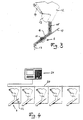
- FIG. 3 shows the installation of a moisture sensor 6 in a baffle plate 10.
- the baffle plate 10 is located below the outflow opening of an additive silo 12.
- the outflow opening of the additive silo 12 can be opened and closed by a pivotable slide 13, which is automatically actuated via a hydraulic setting cylinder 14 can.
- the bulk material 15 emerging from the opening of the silo strikes the baffle plate 10 and is deflected by it in the direction of the moisture sensor 6. Due to the deflection, a sliding material flow 16 with reproducible density and speed is formed on the baffle plate 10.
- the humidity sensor 6 is mounted so that the end plate 1 in a plane of the Baffle plate 10 is mounted so that the electrical leakage field 11 generated by the humidity sensor 6 can penetrate the sliding material flow 16.
- the volume of moisture in the bulk material can be determined. Since the material density is approximately constant in the sliding material flow 16, the measured volume moisture is proportional to the weight moisture of the bulk material. The thus determined weight moisture can now be used to calculate a moisture correction between aggregate and water. This correction takes place in a weighing container, not shown, in which the bulk material 15 is forwarded in the direction of arrow 17.
- FIG. 4 shows a schematic illustration of a plurality of moisture sensors 6 arranged in baffle plates 10, which are operated in parallel.
- the humidity sensors are connected by a common bus line 20 to a central evaluation unit 21. From each humidity sensor 6 to the bus line 20 performs a connection cable 22 which is connected to the socket 5 of the humidity sensor 6.
- a serial data transfer takes place on the bus line.
- two data lines are required in the bus line 20 and in the connection cable 22, in addition, the moisture sensor 6 is supplied with voltage by two additional lines.
- the central evaluation unit 21 transmits a start order to the respective humidity sensor 6, to which a corresponding address is assigned. Then, the arithmetic unit arranged in the humidity sensor starts a measurement, wherein a plurality of measured values are averaged over time. Once the measurement has been completed, the calculated moisture value is transferred to the central evaluation unit 21 as a result.
- the start order of the central evaluation unit may also contain further information, so that the measurement can optionally be carried out in a parameter-oriented manner.
- FIG. 5 shows a block diagram of the arithmetic unit and the components of a humidity sensor connected thereto.
- the stray field capacitor 27 is formed by a housing-side pole 28 and a sensor-side pole 29.
- the housing-side pole 28 is formed by the housing 3 and the adjoining baffle plate 10 and is electrically connected to ground.
- the sensor-side pole 29 is connected to the vapor-deposited metal layer 2. In systems of a voltage between the poles 28 and 29 forms a stray field of the stray field capacitor 27, wherein the capacitance changes of the stray field capacitor 27 are evaluated due to changes in humidity of the sliding material flow 16 by the capacitance measuring circuit 30.
- a resonant circuit 32 is connected consisting of a coil and another capacitor.
- the resonant circuit 32 is attenuated by the amplifier 33 and oscillates at its resonance frequency in the megahertz range.
- the amplitude stabilization 31 keeps the voltage at the stray field capacitor 27 constant. This ensures, on the one hand, that the amplifier 33 is not overdriven, but on the other hand it effectively suppresses the influence of different conductivities of the bulk material. This is explained by the fact that, viewed electrically, the conductivity of the bulk material is an effective resistance parallel to the stray field capacitor 27 whose resistance change is negligible if the voltage at the stray field capacitor is kept constant by the amplitude stabilization 31.
- the output signal of the amplifier is fed to a synchronous counter 34.
- a microcontroller 36 is provided, to which a plurality of measurement signals can be supplied via a multiplexer 40 and an AD converter 43. Furthermore, the microcontroller 36 has an interface to an interface module 44, to which the connection cable 22 can be connected. On the bus 35 of the microcontroller, the synchronous counter 34 and an Eprom 37 is connected.
- the measuring signals of a first temperature sensor 38, a second temperature sensor 39, a reference voltage source 41 and further measuring signals 42 are used as the input signal of the multiplexer 40.
- the first temperature sensor 38 measures the temperature on the capacitance measuring circuit 30, the capacitance measuring circuit is realized as a hybrid circuit.
- As the substrate of the hybrid circuit an aluminum oxide is used, through the good thermal conductivity of a reliable temperature measurement of the first temperature sensor 38 is ensured.
- the second temperature sensor is mounted on the end plate 1 and measures the temperature of the end plate or the sliding on the end plate bulk material. About the terminal 42 can be read by the multiplexer 40 further measuring signals, such as the moisture-specific density of a bulk material.
- the multiplexer 40 is clocked by the microcontroller 36 and supplies the respective multiplex signal to an AD converter 43 whose digital output value is read in by the microcontroller 36.
- the count of the synchronous counter 34 is set via the bus 35 to zero.
- the clock signal of the amplifier 22 then causes the synchronous counter 34 to count up, the count of the synchronous counter 34 representing the number of resonant oscillations of the resonant circuit 32 over a certain period of time.
- the synchronous counter 34 is read out by the microcontroller 36 via the bus 35. From the count and the elapsed time, the frequency of the resonant circuit 32 can be determined, which is a measure of the change in capacitance of the stray field capacitor 27.
- the calculated frequency is now used as an input parameter for a calibration table that was previously loaded by the microcontroller from the Eprom 37 in its memory.
- the output value of the calibration table is a specific humidity value, which as a result is forwarded by the microcontroller 36 via the interface module 44 and the connection cable 22 to the central evaluation unit 21. If appropriate, it is also possible to average over a plurality of measured values before a measured value transmission to the central evaluation unit 21 takes place.
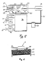
- FIG. 6 shows a section through a calibration device for a humidity sensor for creating a calibration table to be stored in the Eprom 37.
- the moisture sensor 6 is fixed on a metal housing 61 by means of a quick-release 60 before it is put into operation.
- the end plate 1 of the humidity sensor rests on a material sample with known dielectric properties. Due to the known dielectric properties of the material sample, the calibration table can be created as a function of the incoming measurement signals at the multiplexer 40.
- the moisture sensor clamped on the metal housing 21 is first cooled to the lowest permissible operating temperature, that is, for example, to -10 °.
- the humidity sensor is heated to the highest permissible operating temperature, by means of a heating plate 63, which is mounted below the material sample 62.
- a heating plate 63 which is mounted below the material sample 62.
- the heater 63 is always operated at maximum power during the heating process, the temperature inside the humidity sensor 6 increases exponentially and approaches the final value more and more slowly.
- Such a rise in temperature has the disadvantage that, at the beginning of the temperature increase, a rapid sampling of the measured values must take place due to the large changes, while at the end of the measuring process the measured values change only slowly and thus unnecessarily many measuring points are recorded at the same sampling rate. Therefore, it may be particularly advantageous to provide the heater with an additional control, which ensures that the temperature difference between the first and the second temperature sensor remains constant.
- the first temperature sensor is located in the interior of the housing 3 of the humidity sensor 6, while the second temperature sensor is attached to the housing itself, is the constant temperature difference between the two temperature sensors, a constant heat flow ensured by the exterior of the housing in the interior. This also results in an approximately constant increase in temperature inside the housing, which allows a much better recording of the calibration values.
Landscapes
- Chemical & Material Sciences (AREA)
- Chemical Kinetics & Catalysis (AREA)
- Electrochemistry (AREA)
- Physics & Mathematics (AREA)
- Health & Medical Sciences (AREA)
- Life Sciences & Earth Sciences (AREA)
- Analytical Chemistry (AREA)
- Biochemistry (AREA)
- General Health & Medical Sciences (AREA)
- General Physics & Mathematics (AREA)
- Immunology (AREA)
- Pathology (AREA)
- Investigating Or Analyzing Materials By The Use Of Electric Means (AREA)
Applications Claiming Priority (3)
| Application Number | Priority Date | Filing Date | Title |
|---|---|---|---|
| DE19604259 | 1996-02-06 | ||
| DE19610599A DE19610599C2 (de) | 1996-02-06 | 1996-03-18 | Feuchtesensor |
| EP97902211A EP0819248B1 (fr) | 1996-02-06 | 1997-01-23 | Capteur d'humidite |
Related Parent Applications (1)
| Application Number | Title | Priority Date | Filing Date |
|---|---|---|---|
| EP97902211A Division EP0819248B1 (fr) | 1996-02-06 | 1997-01-23 | Capteur d'humidite |
Publications (2)
| Publication Number | Publication Date |
|---|---|
| EP1703277A2 true EP1703277A2 (fr) | 2006-09-20 |
| EP1703277A3 EP1703277A3 (fr) | 2006-11-02 |
Family
ID=36809499
Family Applications (2)
| Application Number | Title | Priority Date | Filing Date |
|---|---|---|---|
| EP06013769A Withdrawn EP1703277A3 (fr) | 1996-02-06 | 1997-01-23 | Capteur d'humidité |
| EP06013768A Withdrawn EP1717576A1 (fr) | 1996-02-06 | 1997-01-23 | Capteur d'humidité |
Family Applications After (1)
| Application Number | Title | Priority Date | Filing Date |
|---|---|---|---|
| EP06013768A Withdrawn EP1717576A1 (fr) | 1996-02-06 | 1997-01-23 | Capteur d'humidité |
Country Status (1)
| Country | Link |
|---|---|
| EP (2) | EP1703277A3 (fr) |
Cited By (1)
| Publication number | Priority date | Publication date | Assignee | Title |
|---|---|---|---|---|
| DE102021130515A1 (de) | 2021-11-22 | 2023-05-25 | Küpper-Weisser GmbH | Verfahren und Vorrichtung zur Verteilung von Streustoffen |
Citations (1)
| Publication number | Priority date | Publication date | Assignee | Title |
|---|---|---|---|---|
| DE3612282A1 (de) | 1986-03-13 | 1987-09-17 | Liebherr Mischtechnik Gmbh | Verfahren zur messung der feuchtigkeit von schuettelstoffen im fliessenden materialstrom |
Family Cites Families (9)
| Publication number | Priority date | Publication date | Assignee | Title |
|---|---|---|---|---|
| DE2205596A1 (de) * | 1971-02-08 | 1972-08-17 | Burrows Equipment Co | Gerät zur Bestimmung eines physikalischen Parameters, insbesondere Feuchtigkeitsprüfgerät für Körner |
| US4064455A (en) * | 1976-11-18 | 1977-12-20 | Hopkins Manufacturing Corporation | Fluid condition monitoring system |
| US4571543A (en) * | 1983-03-28 | 1986-02-18 | Southwest Medical Products, Inc. | Specific material detection and measuring device |
| DE3329025A1 (de) * | 1983-08-11 | 1985-02-28 | Kurt 7895 Klettgau Arnold | Verfahren und einrichtung zum bestimmen des feuchtegehalts von getreide und anderen koernigen stoffen |
| SU1376030A1 (ru) * | 1985-07-24 | 1988-02-23 | Предприятие П/Я Г-4132 | Емкостный измеритель физико-механических параметров нитевидных изделий |
| US4853614A (en) * | 1988-03-11 | 1989-08-01 | Carver Robert L | Method and apparatus for measuring moisture content of granular material |
| IT1258181B (it) * | 1992-08-05 | 1996-02-20 | Apparecchiatura per la determinazione della frazione d'acqua in una corrente di idrocarburi luquidi anche in presenza di gas | |
| US5469364A (en) * | 1993-03-15 | 1995-11-21 | Hughey; Bradley W. | Apparatus and methods for measuring and detecting variations in the value of a capacitor |
| US5502659A (en) * | 1994-06-06 | 1996-03-26 | Endress+Hauser, Inc. | Method and apparatus for calibrating moisture sensors |
-
1997
- 1997-01-23 EP EP06013769A patent/EP1703277A3/fr not_active Withdrawn
- 1997-01-23 EP EP06013768A patent/EP1717576A1/fr not_active Withdrawn
Patent Citations (1)
| Publication number | Priority date | Publication date | Assignee | Title |
|---|---|---|---|---|
| DE3612282A1 (de) | 1986-03-13 | 1987-09-17 | Liebherr Mischtechnik Gmbh | Verfahren zur messung der feuchtigkeit von schuettelstoffen im fliessenden materialstrom |
Cited By (1)
| Publication number | Priority date | Publication date | Assignee | Title |
|---|---|---|---|---|
| DE102021130515A1 (de) | 2021-11-22 | 2023-05-25 | Küpper-Weisser GmbH | Verfahren und Vorrichtung zur Verteilung von Streustoffen |
Also Published As
| Publication number | Publication date |
|---|---|
| EP1703277A3 (fr) | 2006-11-02 |
| EP1717576A1 (fr) | 2006-11-02 |
Similar Documents
| Publication | Publication Date | Title |
|---|---|---|
| EP0819248B1 (fr) | Capteur d'humidite | |
| DE69704997T2 (de) | Verfahren und Vorrichtung zum Netzen von Getreide | |
| EP0501099B1 (fr) | Dispositif pour mesurer le débit massique avec un condensateur de mesure | |
| EP2183577B1 (fr) | Procédé et dispositif de mesure d'une valeur d'humidité indépendante de la densité et d'une valeur de densité de matériaux diélectriques à partir des décalages de fréquence entre deux résonateurs hyperfréquence ou deux modes d'un résonateur hyperfréquence | |
| DE3003821C2 (de) | Vorrichtung zum Regeln der Durchflußmenge | |
| DE1573968A1 (de) | Einrichtung zum Messen der Eigenschaften eines Materials | |
| DE3024794A1 (de) | Verfahren und vorrichtung zur bestimmung von kenngroessen, insbesondere von getreide | |
| EP0829007B1 (fr) | Procede et dispositif de detection continue de l'humidite d'un produit en vrac | |
| DE19610599C2 (de) | Feuchtesensor | |
| EP0095657B1 (fr) | Procédé de régulation automatique des installations de préparation de sable de fonderie | |
| DE1498819C3 (de) | Vorrichtung zur Bestimmung einer charakteristischen Eigenschaft eines Materials | |
| EP1703277A2 (fr) | Capteur d'humidité | |
| DE3306462A1 (de) | Elektrisches feuchtemessgeraet | |
| DE3612282C2 (fr) | ||
| DE1498988A1 (de) | Verfahren und Vorrichtung zum Messen des Feuchtigkeitsgehalts koernigen Materials | |
| DE2545792A1 (de) | Steuervorrichtung und verfahren zur steuerung der dosierung von mit einem mischgut zu vermischenden zugabemengen | |
| DE2216379C3 (de) | Verfahren zur Eichung einer radiometrisch arbeitenden Feuchtemeßanlage für Schüttgüter, insbesondere Koks | |
| DE2531141C3 (fr) | ||
| EP0943913A2 (fr) | Procédé et appareil pour déterminer la composition des particules solides fluidisables | |
| DE3306460A1 (de) | Elektrisches feuchtemessgeraet | |
| DE4306905A1 (de) | Verfahren zum Fördern der Verbrennung in einer Brennkraftmaschine und Vorrichtung zur Ausübung dieses Verfahrens | |
| WO2019096766A1 (fr) | Dispositif de détermination de l'humidité et/ou de la conductivité d'un milieu | |
| EP1321566A1 (fr) | Appareil de traitement du linge avec une capteur d'humité et procédé pour la détermination de la teneur en humidité du linge | |
| EP0470367B1 (fr) | Dispositif de mesure de la conductivité des fluides | |
| DD290953A5 (de) | Vorrichtung und verfahren zur kontinuierlichen feuchtemessung von keramischen schuettguetern |
Legal Events
| Date | Code | Title | Description |
|---|---|---|---|
| PUAI | Public reference made under article 153(3) epc to a published international application that has entered the european phase |
Free format text: ORIGINAL CODE: 0009012 |
|
| 17P | Request for examination filed |
Effective date: 20060703 |
|
| AC | Divisional application: reference to earlier application |
Ref document number: 0819248 Country of ref document: EP Kind code of ref document: P |
|
| AK | Designated contracting states |
Kind code of ref document: A2 Designated state(s): AT CH DE DK ES FR GB IT LI NL SE |
|
| PUAL | Search report despatched |
Free format text: ORIGINAL CODE: 0009013 |
|
| AK | Designated contracting states |
Kind code of ref document: A3 Designated state(s): AT CH DE DK ES FR GB IT LI NL SE |
|
| RIC1 | Information provided on ipc code assigned before grant |
Ipc: G01N 27/22 20060101AFI20060816BHEP Ipc: G01R 27/26 20060101ALI20060922BHEP |
|
| 17Q | First examination report despatched |
Effective date: 20061211 |
|
| AKX | Designation fees paid |
Designated state(s): AT CH DE DK ES FR GB IT LI NL SE |
|
| STAA | Information on the status of an ep patent application or granted ep patent |
Free format text: STATUS: THE APPLICATION IS DEEMED TO BE WITHDRAWN |
|
| 18D | Application deemed to be withdrawn |
Effective date: 20070619 |