EP1703286A1 - Schwingungssensor oder Meßaufnehmer - Google Patents
Schwingungssensor oder Meßaufnehmer Download PDFInfo
- Publication number
- EP1703286A1 EP1703286A1 EP06005345A EP06005345A EP1703286A1 EP 1703286 A1 EP1703286 A1 EP 1703286A1 EP 06005345 A EP06005345 A EP 06005345A EP 06005345 A EP06005345 A EP 06005345A EP 1703286 A1 EP1703286 A1 EP 1703286A1
- Authority
- EP
- European Patent Office
- Prior art keywords
- clamping
- vibration sensor
- cable
- winding space
- transducer
- Prior art date
- Legal status (The legal status is an assumption and is not a legal conclusion. Google has not performed a legal analysis and makes no representation as to the accuracy of the status listed.)
- Granted
Links
- 238000004804 winding Methods 0.000 claims abstract description 20
- 238000009434 installation Methods 0.000 description 3
- 239000004020 conductor Substances 0.000 description 2
- 238000005516 engineering process Methods 0.000 description 2
Images
Classifications
-
- G—PHYSICS
- G01—MEASURING; TESTING
- G01D—MEASURING NOT SPECIALLY ADAPTED FOR A SPECIFIC VARIABLE; ARRANGEMENTS FOR MEASURING TWO OR MORE VARIABLES NOT COVERED IN A SINGLE OTHER SUBCLASS; TARIFF METERING APPARATUS; MEASURING OR TESTING NOT OTHERWISE PROVIDED FOR
- G01D11/00—Component parts of measuring arrangements not specially adapted for a specific variable
- G01D11/24—Housings ; Casings for instruments
- G01D11/245—Housings for sensors
-
- G—PHYSICS
- G01—MEASURING; TESTING
- G01D—MEASURING NOT SPECIALLY ADAPTED FOR A SPECIFIC VARIABLE; ARRANGEMENTS FOR MEASURING TWO OR MORE VARIABLES NOT COVERED IN A SINGLE OTHER SUBCLASS; TARIFF METERING APPARATUS; MEASURING OR TESTING NOT OTHERWISE PROVIDED FOR
- G01D11/00—Component parts of measuring arrangements not specially adapted for a specific variable
- G01D11/30—Supports specially adapted for an instrument; Supports specially adapted for a set of instruments
-
- G—PHYSICS
- G01—MEASURING; TESTING
- G01H—MEASUREMENT OF MECHANICAL VIBRATIONS OR ULTRASONIC, SONIC OR INFRASONIC WAVES
- G01H1/00—Measuring characteristics of vibrations in solids by using direct conduction to the detector
-
- G—PHYSICS
- G01—MEASURING; TESTING
- G01P—MEASURING LINEAR OR ANGULAR SPEED, ACCELERATION, DECELERATION, OR SHOCK; INDICATING PRESENCE, ABSENCE, OR DIRECTION, OF MOVEMENT
- G01P1/00—Details of instruments
- G01P1/02—Housings
- G01P1/023—Housings for acceleration measuring devices
-
- H—ELECTRICITY
- H01—ELECTRIC ELEMENTS
- H01R—ELECTRICALLY-CONDUCTIVE CONNECTIONS; STRUCTURAL ASSOCIATIONS OF A PLURALITY OF MUTUALLY-INSULATED ELECTRICAL CONNECTING ELEMENTS; COUPLING DEVICES; CURRENT COLLECTORS
- H01R13/00—Details of coupling devices of the kinds covered by groups H01R12/70 or H01R24/00 - H01R33/00
- H01R13/58—Means for relieving strain on wire connection, e.g. cord grip, for avoiding loosening of connections between wires and terminals within a coupling device terminating a cable
- H01R13/5833—Means for relieving strain on wire connection, e.g. cord grip, for avoiding loosening of connections between wires and terminals within a coupling device terminating a cable the cable being forced in a tortuous or curved path, e.g. knots in cable
-
- H—ELECTRICITY
- H01—ELECTRIC ELEMENTS
- H01R—ELECTRICALLY-CONDUCTIVE CONNECTIONS; STRUCTURAL ASSOCIATIONS OF A PLURALITY OF MUTUALLY-INSULATED ELECTRICAL CONNECTING ELEMENTS; COUPLING DEVICES; CURRENT COLLECTORS
- H01R13/00—Details of coupling devices of the kinds covered by groups H01R12/70 or H01R24/00 - H01R33/00
- H01R13/66—Structural association with built-in electrical component
- H01R13/665—Structural association with built-in electrical component with built-in electronic circuit
- H01R13/6683—Structural association with built-in electrical component with built-in electronic circuit with built-in sensor
Definitions
- the present invention relates to a vibration sensor or transducer in an ergonomically advantageous embodiment.
- the present invention solves the problem described in a clever and at the same time cost-effective manner with the means as they are mentioned in the independent claims.
- the invention is therefore characterized in particular by a vibration sensor or a transducer with a connecting cable for electrical supply and / or signal voltages.
- a clamping or winding space is provided on the underside of the sensor housing, wherein the connecting cable is disposable with one or more windings, and wherein the one or more windings lie in a single plane.
- the connecting cable in the tangential direction (based on the one or more turns) from the clamping or winding space (42) exit into the external environment.
- connection cables of vibration sensors or accelerometers are either mounted coaxially to the longitudinal axis of such a sensor and can be firmly attached or connected by means of a coaxial connector, or can be supplied from the side, ie exit in the radial direction. In the latter case, fixed cable stop is preferred.
- the invention turns away radically from this technology used for decades and is based on now provide a laterally tangentially directed on the sensor leakage of connecting cables. In addition, this should be done in conjunction with a device located on the sensor, which allows to deposit the corresponding connection cable in a winding chamber proportionally when properly screwed such sensors.
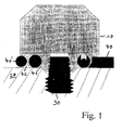
- a vibration sensor or accelerometer which is not shown here for reasons of clarity.
- On the underside of the sensor housing is a provided with, for example, an internal thread attachment piece 14, which can be screwed in a conventional manner to a threaded connecting bolt 30 and thus to the surface of a machine part 20.
- the sensor housing may also be provided with a measuring pin with external thread; Both alternatives can be considered for the present invention.
- the signal voltage supplied by the sensor is applied to the inner conductor of a coaxial cable, while the corresponding outer conductor is contacted by the housing of the sensor or, preferably, by an additional connection element.
- the coaxial cable is then deposited about half a turn in a cable chamber 41 and is There thus guided so that it can leave the cable chamber in an approximately tangential direction through a designated opening or recess to the outside.
- the coaxial cable can thus be wound when tightening the sensor in the clamping or winding space 42 with one or more windings.
- the clamping space 42 is located radially relative to the cable chamber 41 radially outboard.
- the clamping space 42 is dimensioned such that at least one turn, preferably two or more turns of the cable 40 (indicated in cross section by reference numeral 40 ') can be received.
- the height of the terminal space is preferably such that the cable 40 is held in position by slight pressure on its top or bottom (ie, for example, in its radial direction), but on the other hand without damage or manually around the sensor or be unwound can.
- the connecting cable is thus, if the vibration sensor or transducer is firmly screwed, also protected, for example by means of a predefined load in the direction of its diameter and corresponding slight deformation against unintentional unwinding from its desired position; In particular, it can therefore not give rise to false signal voltages in vibrations of the machine to be measured.
- the cable can be led out of any angular position of the sensor in the tangential direction.
- it can be placed immediately and directly over the surface of the machine part 20, so that it is best protected against damage from moving parts or tools, especially if it additionally fixed by means of tape o. The like. On the machine to be checked and additionally protected becomes.
Landscapes
- Physics & Mathematics (AREA)
- General Physics & Mathematics (AREA)
- Geophysics And Detection Of Objects (AREA)
- Measurement Of Mechanical Vibrations Or Ultrasonic Waves (AREA)
- Electrophonic Musical Instruments (AREA)
- Measurement Of Length, Angles, Or The Like Using Electric Or Magnetic Means (AREA)
Abstract
Description
- Die vorliegende Erfindung betrifft einen Schwingungssensor oder Meßaufnehmer in ergonomisch vorteilhafter Ausgestaltung.
- Beim Anbringen und Befestigen von Schwingungssensoren oder Accelerometern an Maschinen ist es stets von Bedeutung, einerseits die zugehörigen Anschlußdrähte bzw. -kabel fachgerecht zu verlegen und zu fixieren, damit die zu messenden Signale nicht durch Eigenbewegung des Kabels verfälscht werden. Andererseits sollte der Zeitbedarf für eine solche fachgerechte Verlegung und Plazierung von Kabeln möglichst gering sein. Herkömmliche Schwingungssensoren und Accelerometer sind hier in gewisser Weise problembehaftet, insbesondere können bei eiligen Verlegungsarbeiten sogar die Kabel der Schwingungssensoren versehentlich beschädigt werden, speziell solche, die fest an einem Sensor befestigt (angeschlagen) sind.
- Aus der
DE 20301106 ist eine Vorrichtung bekannt, mit welcher es in relativ einfacher Weise möglich ist, installationsbedingte Beschädigungen von Anschlußkabeln der obengenannten Sensoren zu vermeiden. Dies gilt insbesondere für Sensoren mit seitlich austretendem Kabel. Allerdings ist ein spezielles Zusatzteil erforderlich, und auch die Sensoren sollten für die dort gezeigte Ausführungsform ein modifiziertes Anschlußgewinde aufweisen. - Die vorliegende Erfindung löst das geschilderte Problem in geschickter und zugleich kostengünstiger Weise mit den Mitteln, wie sie in den unabhängigen Patentansprüchen genannt werden.
- Die Erfindung zeichnet sich also insbesondere durch einen Schwingungssensor oder einen Meßaufnehmer mit einem Anschlußkabel für elektrische Versorgungs- und/oder Signalspannungen aus. Speziell ist ein Klemm- oder Wickelraum an der Unterseite des Sensor-Gehäuses vorhanden, wohinein das Anschlußkabel mit einer oder mehreren Windungen deponierbar ist, und wobei die eine oder mehrere Windungen in einer einzigen Ebene liegen. Dabei soll das Anschlußkabel in tangentialer Richtung (bezogen auf die ein oder mehrere Windungen) aus dem Klemm- oder Wickelraum (42) in die äußere Umgebung austreten.
- Nach herkömmlicher Technologie werden Anschlußkabel von Schwingungssensoren oder Accelerometer entweder koaxial zur Längsachse eines solchen Sensors angebracht und können fest angeschlagen sein oder mittels Koaxial-Steckverbindung angeschlossen werden, oder aber von der Seite zugeführt werden, also in radialer Richtung austreten. Im letzteren Falle wird fester Kabelanschlag bevorzugt. - Die Erfindung wendet sich von dieser seit Jahrzehnten verwendeten Technik radikal ab und basiert darauf, nunmehr ein am Sensor seitlich tangential gerichtetes Austreten von Anschlußkabeln vorzusehen. Außerdem soll dies in Verbindung mit einer am Sensor befindlichen Vorrichtung geschehen, die es gestattet, beim bestimmungsgemäßen Einschrauben solcher Sensoren das jeweils zugehörige Anschlußkabel in einer Wickelkammer anteilig zu deponieren. Mit dieser Maßnahme wird also einerseits einer Beschädigung des Anschlußkabels beim Anbringen eines Sensors wirksam vorgebeugt, andererseits wird gleichzeitig ein Zugentlastungsmechanismus bereitgestellt, der darüberhinaus auch noch als Knickschutz funktioniert. - Eine Befestigung von erfindungsgemäß ausgestatteten Sensoren mit nachfolgend fachgerechter Verlegung und ggf. Fixierung der zugehörigen Anschlußkabel gestaltet sich also besonders einfach und zeitsparend. Darüberhinaus stellt die erfindungsgemäß vorgesehene Kabelzufuhr auch nach Beendigung der Installationsarbeiten für einen solchen Sensor einen verbesserten Schutz gegen versehentliches Abreißen oder Beschädigen solcher Anschlußkabel dar.
- Die Erfindung wird im folgenden anhand der Zeichnung erläutert.
- Innerhalb eines Sensorgehäuses 10 befindet sich ein Schwingungssensor oder Accelerometer, welcher hier aus Gründen der Übersichtlichkeit nicht näher gezeigt ist. An der Unterseite des Sensorgehäuses befindet sich ein mit z.B. einem Innengewinde versehener Befestigungsstutzen 14, welcher in an sich bekannter Weise an einen schraubbaren Verbindungsbolzen 30 und somit an die Oberfläche eines Maschinenteils 20 angeschraubt werden kann. Anstelle des Befestigungsstutzens kann das Sensorgehäuse auch mit einem Meßbolzen mit Außengewinde versehen sein; für die vorliegende Erfindung kommen beide Alternativen in Betracht. Mit einer Kontaktierung 12 wird die vom Sensor abgegebene Signalspannung an den Innenleiter eines Koaxialkabels gelegt, während der entsprechende Außenleiter durch das Gehäuse des Sensors oder, bevorzugt, durch ein zusätzliches Anschlußelement kontaktiert wird. Das Koaxialkabel ist sodann etwa eine halbe Windung in einer Kabelkammer 41 deponiert und wird dort somit so geführt, daß es die Kabelkammer in etwa tangentialer Richtung durch eine vorgesehene Öffnung oder Aussparung nach außen verlassen kann. Das Koaxialkabel kann somit beim Festschrauben des Sensors im Klemm- oder Wickelraum 42 mit einer oder mehreren Windungen aufgewickelt werden. Dieser Aspekt stellt einen wesentlichen Teil der Erfindung dar. Der Klemmraum 42 befindet sich relativ zur Kabelkammer 41 radial gesehen außenliegend. Der Klemmraum 42 ist so bemessen, daß zumindest eine Windung, bevorzugt zwei oder mehr Windungen des Kabels 40 (im Querschnitt durch Bezugszeichen 40 ' gekennzeichnet) aufgenommen werden können. Die Höhe des Klemmraums ist bevorzugt so bemessen, daß das Kabel 40 durch leichten Druck auf seine Ober- bzw. Unterseite (also z.B. in dessen radialer Richtung) in Position gehalten wird, andererseits aber ohne Beschädigung auch manuell um den Sensor auf- oder abgewickelt werden kann. Das Anschlußkabel ist also, wenn der Schwingungssensor oder Meßaufnehmer fest eingeschraubt ist, auch z.B. auch mittels einer vordefinierten Belastung in Richtung seines Durchmessers und entsprechender leichter Verformung vor unbeabsichtigtem Abspulen aus seiner Sollposition geschützt; insbesondere kann es daher bei Vibrationen der zu vermessenden Maschine nicht zu Fehlsignalspannungen Anlaß geben. - Wie ersichtlich, kann das Kabel aus jeder beliebigen Winkelposition vom Sensor in tangentialer Richtung herausgeführt werden. Außerdem kann es sofort und direkt über die Oberfläche des Maschinenteils 20 gelegt werden, so daß es vor Beschädigung durch bewegte Teile oder Werkzeuge bestmöglich geschützt ist, insbesondere dann, wenn es zusätzlich mittels Klebeband o. dgl. an der zu überprüfenden Maschine fixiert und zusätzlich geschützt wird.
Claims (4)
- Schwingungssensor oder Meßaufnehmer mit einem Anschlußkabel (40) für elektrische Versorgungs- und/oder Signalspannungen, gekennzeichnet durch einen Klemm- oder Wickelraum (42) an der Unterseite des Sensor-Gehäuses (10), in welchen das Anschlußkabel mit einer oder mehreren Windungen deponierbar ist, und wobei die eine oder mehrere Windungen in einer einzigen Ebene liegen, dergestalt, daß das Anschlußkabel in tangentialer Richtung bezogen auf die ein oder mehrere Windungen aus dem Klemm- oder Wickelraum (42) in die äußere Umgebung austritt.
- Schwingungssensor oder Meßaufnehmer nach Anspruch 1, mit einer zusätzlichen Kabelkammer (41), welche im Vergleich zum Klemm- oder Wickelraum (42) radial innenliegend angeordnet ist.
- Schwingungssensor oder Meßaufnehmer nach einem der vorhergehenden Ansprüche, bei welchem der Klemm- oder Wickelraum (42) so dimensioniert ist, daß beim bestimmungsgemäßen Befestigen des Schwingungssensors oder Meßaufnehmers durch Einschrauben ein gleichzeitiges Aufwickeln des Anschlußkabels (40) in einer einzigen Ebene mit einer oder mehreren Windungen stattfindet.
- Schwingungssensor oder Meßaufnehmer nach Anspruch 3, bei welchem der Klemm- und Wickelraum (42) so dimensioniert ist, daß das Anschlußkabel (40) mittels einer vordefinierten radial auf dieses gerichteten Belastung und zugehöriger Verformung vor unbeabsichtigtem Abspulen aus seiner Sollposition geschützt ist.
Applications Claiming Priority (1)
| Application Number | Priority Date | Filing Date | Title |
|---|---|---|---|
| DE102005012466 | 2005-03-16 |
Publications (2)
| Publication Number | Publication Date |
|---|---|
| EP1703286A1 true EP1703286A1 (de) | 2006-09-20 |
| EP1703286B1 EP1703286B1 (de) | 2008-05-14 |
Family
ID=36659940
Family Applications (1)
| Application Number | Title | Priority Date | Filing Date |
|---|---|---|---|
| EP06005345A Expired - Lifetime EP1703286B1 (de) | 2005-03-16 | 2006-03-16 | Schwingungssensor oder Meßaufnehmer |
Country Status (4)
| Country | Link |
|---|---|
| US (1) | US7513162B2 (de) |
| EP (1) | EP1703286B1 (de) |
| AT (1) | ATE395604T1 (de) |
| DE (1) | DE502006000758D1 (de) |
Cited By (2)
| Publication number | Priority date | Publication date | Assignee | Title |
|---|---|---|---|---|
| WO2016066972A1 (fr) * | 2014-10-31 | 2016-05-06 | 01Db-Metravib | Dispositif et procede pour monter et orienter un capteur sur un support |
| US11660049B2 (en) | 2015-12-22 | 2023-05-30 | The University Of Sheffield | Apparatus and methods for determining force applied to the tip of a probe |
Families Citing this family (1)
| Publication number | Priority date | Publication date | Assignee | Title |
|---|---|---|---|---|
| EP2120317A1 (de) * | 2008-05-14 | 2009-11-18 | ABB Research LTD | Verfahren und Vorrichtung zur Bestimmung der mechanischen Resonanzfrequenz eines Schwingungsmodus für ein Spulengehäuse eines Transformators |
Citations (3)
| Publication number | Priority date | Publication date | Assignee | Title |
|---|---|---|---|---|
| EP0776065A1 (de) * | 1995-11-21 | 1997-05-28 | Dr. Johannes Heidenhain GmbH | Winkelmesseinrichtung |
| DE20301106U1 (de) | 2003-01-24 | 2003-04-24 | Prüftechnik Dieter Busch AG, 85737 Ismaning | Vorrichtung zum Befestigen eines Beschleunigungsaufnehmers |
| DE10304905B3 (de) * | 2003-02-06 | 2004-05-13 | Siemens Ag | Abdeckung für ein elektronisches Gerät |
Family Cites Families (7)
| Publication number | Priority date | Publication date | Assignee | Title |
|---|---|---|---|---|
| DE3716464A1 (de) * | 1987-05-16 | 1988-12-08 | Danfoss As | Rotationsmaschine mit drehwinkel-messvorrichtung |
| JPH10222300A (ja) * | 1997-02-06 | 1998-08-21 | Takashima Kk | コンピュータ装置およびマウス |
| EP1211500B1 (de) * | 2000-12-01 | 2009-09-02 | Nsk Ltd | Wälzlagervorrichtung mit Sensor |
| DE10316870A1 (de) * | 2003-04-11 | 2004-10-21 | Dr. Johannes Heidenhain Gmbh | Positionsmesseinrichtung |
| JP4358678B2 (ja) * | 2004-05-14 | 2009-11-04 | 株式会社小松製作所 | 変位量測定装置 |
| US7312602B2 (en) * | 2004-07-23 | 2007-12-25 | Paul Hoopengarner | Electrical meter with retractable leads |
| DE102004060864A1 (de) * | 2004-12-17 | 2006-06-22 | Dr. Johannes Heidenhain Gmbh | Winkelmesseinrichtung |
-
2006
- 2006-03-16 AT AT06005345T patent/ATE395604T1/de not_active IP Right Cessation
- 2006-03-16 EP EP06005345A patent/EP1703286B1/de not_active Expired - Lifetime
- 2006-03-16 DE DE502006000758T patent/DE502006000758D1/de not_active Expired - Lifetime
- 2006-04-14 US US11/279,761 patent/US7513162B2/en active Active
Patent Citations (3)
| Publication number | Priority date | Publication date | Assignee | Title |
|---|---|---|---|---|
| EP0776065A1 (de) * | 1995-11-21 | 1997-05-28 | Dr. Johannes Heidenhain GmbH | Winkelmesseinrichtung |
| DE20301106U1 (de) | 2003-01-24 | 2003-04-24 | Prüftechnik Dieter Busch AG, 85737 Ismaning | Vorrichtung zum Befestigen eines Beschleunigungsaufnehmers |
| DE10304905B3 (de) * | 2003-02-06 | 2004-05-13 | Siemens Ag | Abdeckung für ein elektronisches Gerät |
Cited By (4)
| Publication number | Priority date | Publication date | Assignee | Title |
|---|---|---|---|---|
| WO2016066972A1 (fr) * | 2014-10-31 | 2016-05-06 | 01Db-Metravib | Dispositif et procede pour monter et orienter un capteur sur un support |
| FR3027975A1 (fr) * | 2014-10-31 | 2016-05-06 | 01Db-Metravib | Dispositif et procede pour monter et orienter un capteur sur un support |
| US11660049B2 (en) | 2015-12-22 | 2023-05-30 | The University Of Sheffield | Apparatus and methods for determining force applied to the tip of a probe |
| US12310753B2 (en) | 2015-12-22 | 2025-05-27 | The University Of Sheffield | Apparatus and methods for determining force applied to the tip of a probe |
Also Published As
| Publication number | Publication date |
|---|---|
| US20060207331A1 (en) | 2006-09-21 |
| US7513162B2 (en) | 2009-04-07 |
| ATE395604T1 (de) | 2008-05-15 |
| EP1703286B1 (de) | 2008-05-14 |
| DE502006000758D1 (de) | 2008-06-26 |
Similar Documents
| Publication | Publication Date | Title |
|---|---|---|
| DE102008032075A1 (de) | Befestigungsmechanismus für einen Positionsdetektionssensor | |
| DE3502178A1 (de) | Hoergeraet | |
| DE102007030450A1 (de) | Anschlussplatte für einen Klemmkasten | |
| DE102005060676A1 (de) | Positionssensor in Stabbauweise sowie Verfahren zum Austausch | |
| DE29905700U1 (de) | Sensoranordnung | |
| EP1703286B1 (de) | Schwingungssensor oder Meßaufnehmer | |
| DE112013004244B4 (de) | Verdrahtungsvorrichtung | |
| DE102006012494A1 (de) | Schwingungssensor oder Meßaufnehmer | |
| DE102021121686A1 (de) | Sensoreinrichtung zur Erfassung der Position eines Spannelements einer Spann- oder Greifvorrichtung und Spann- oder Greifvorrichtung | |
| EP1386332B1 (de) | Elektromagnetische stelleinrichtung | |
| DE2909247A1 (de) | Verschleissanzeige fuer bremsbelaege | |
| DE3911980C1 (de) | ||
| DE202008007403U1 (de) | Halterung für elektronische Wegmesssonden | |
| DE19543372A1 (de) | Winkelmeßeinrichtung | |
| DE2648824C2 (de) | Elektrische Maschine | |
| DE4431675B4 (de) | Schraubvorrichtung zum ultraschallgesteuerten Anziehen von Schraubverbindungen | |
| DE8632990U1 (de) | Berührungsloser Sensor | |
| DE20301106U1 (de) | Vorrichtung zum Befestigen eines Beschleunigungsaufnehmers | |
| EP1557649B1 (de) | Anschlusskopf für ein Messgerät | |
| DE102022108520B3 (de) | Verstellvorrichtung | |
| AT399601B (de) | Stromwandler für einen hochspannungsleiter | |
| DE112008000677T5 (de) | Sensorvorrichtung | |
| DE102019215108A1 (de) | Sensoranordnung zur Erfassung mindestens einer Eigenschaft eines fluiden Mediums, vorzugsweise zur Druckmessung | |
| DE29805316U1 (de) | Elektrisch leitende Ankopplung für die Abschirmung einer elektrischen Leitung | |
| EP0658393A1 (de) | Schweissvorrichtung |
Legal Events
| Date | Code | Title | Description |
|---|---|---|---|
| PUAI | Public reference made under article 153(3) epc to a published international application that has entered the european phase |
Free format text: ORIGINAL CODE: 0009012 |
|
| AK | Designated contracting states |
Kind code of ref document: A1 Designated state(s): AT BE BG CH CY CZ DE DK EE ES FI FR GB GR HU IE IS IT LI LT LU LV MC NL PL PT RO SE SI SK TR |
|
| AX | Request for extension of the european patent |
Extension state: AL BA HR MK YU |
|
| 17P | Request for examination filed |
Effective date: 20061109 |
|
| 17Q | First examination report despatched |
Effective date: 20070129 |
|
| AKX | Designation fees paid |
Designated state(s): AT BE BG CH CY CZ DE DK EE ES FI FR GB GR HU IE IS IT LI LT LU LV MC NL PL PT RO SE SI SK TR |
|
| GRAP | Despatch of communication of intention to grant a patent |
Free format text: ORIGINAL CODE: EPIDOSNIGR1 |
|
| GRAS | Grant fee paid |
Free format text: ORIGINAL CODE: EPIDOSNIGR3 |
|
| GRAA | (expected) grant |
Free format text: ORIGINAL CODE: 0009210 |
|
| AK | Designated contracting states |
Kind code of ref document: B1 Designated state(s): AT BE BG CH CY CZ DE DK EE ES FI FR GB GR HU IE IS IT LI LT LU LV MC NL PL PT RO SE SI SK TR |
|
| REG | Reference to a national code |
Ref country code: GB Ref legal event code: FG4D Free format text: NOT ENGLISH |
|
| REG | Reference to a national code |
Ref country code: CH Ref legal event code: EP |
|
| REG | Reference to a national code |
Ref country code: IE Ref legal event code: FG4D Free format text: LANGUAGE OF EP DOCUMENT: GERMAN |
|
| REF | Corresponds to: |
Ref document number: 502006000758 Country of ref document: DE Date of ref document: 20080626 Kind code of ref document: P |
|
| REG | Reference to a national code |
Ref country code: SE Ref legal event code: TRGR |
|
| PG25 | Lapsed in a contracting state [announced via postgrant information from national office to epo] |
Ref country code: SI Free format text: LAPSE BECAUSE OF FAILURE TO SUBMIT A TRANSLATION OF THE DESCRIPTION OR TO PAY THE FEE WITHIN THE PRESCRIBED TIME-LIMIT Effective date: 20080514 |
|
| PG25 | Lapsed in a contracting state [announced via postgrant information from national office to epo] |
Ref country code: FI Free format text: LAPSE BECAUSE OF FAILURE TO SUBMIT A TRANSLATION OF THE DESCRIPTION OR TO PAY THE FEE WITHIN THE PRESCRIBED TIME-LIMIT Effective date: 20080514 Ref country code: ES Free format text: LAPSE BECAUSE OF FAILURE TO SUBMIT A TRANSLATION OF THE DESCRIPTION OR TO PAY THE FEE WITHIN THE PRESCRIBED TIME-LIMIT Effective date: 20080825 |
|
| NLV1 | Nl: lapsed or annulled due to failure to fulfill the requirements of art. 29p and 29m of the patents act | ||
| PG25 | Lapsed in a contracting state [announced via postgrant information from national office to epo] |
Ref country code: LV Free format text: LAPSE BECAUSE OF FAILURE TO SUBMIT A TRANSLATION OF THE DESCRIPTION OR TO PAY THE FEE WITHIN THE PRESCRIBED TIME-LIMIT Effective date: 20080514 Ref country code: PL Free format text: LAPSE BECAUSE OF FAILURE TO SUBMIT A TRANSLATION OF THE DESCRIPTION OR TO PAY THE FEE WITHIN THE PRESCRIBED TIME-LIMIT Effective date: 20080514 Ref country code: NL Free format text: LAPSE BECAUSE OF FAILURE TO SUBMIT A TRANSLATION OF THE DESCRIPTION OR TO PAY THE FEE WITHIN THE PRESCRIBED TIME-LIMIT Effective date: 20080514 |
|
| PG25 | Lapsed in a contracting state [announced via postgrant information from national office to epo] |
Ref country code: IS Free format text: LAPSE BECAUSE OF FAILURE TO SUBMIT A TRANSLATION OF THE DESCRIPTION OR TO PAY THE FEE WITHIN THE PRESCRIBED TIME-LIMIT Effective date: 20080914 |
|
| REG | Reference to a national code |
Ref country code: IE Ref legal event code: FD4D |
|
| PG25 | Lapsed in a contracting state [announced via postgrant information from national office to epo] |
Ref country code: LT Free format text: LAPSE BECAUSE OF FAILURE TO SUBMIT A TRANSLATION OF THE DESCRIPTION OR TO PAY THE FEE WITHIN THE PRESCRIBED TIME-LIMIT Effective date: 20080514 Ref country code: IE Free format text: LAPSE BECAUSE OF FAILURE TO SUBMIT A TRANSLATION OF THE DESCRIPTION OR TO PAY THE FEE WITHIN THE PRESCRIBED TIME-LIMIT Effective date: 20080514 Ref country code: DK Free format text: LAPSE BECAUSE OF FAILURE TO SUBMIT A TRANSLATION OF THE DESCRIPTION OR TO PAY THE FEE WITHIN THE PRESCRIBED TIME-LIMIT Effective date: 20080514 Ref country code: CZ Free format text: LAPSE BECAUSE OF FAILURE TO SUBMIT A TRANSLATION OF THE DESCRIPTION OR TO PAY THE FEE WITHIN THE PRESCRIBED TIME-LIMIT Effective date: 20080514 |
|
| PG25 | Lapsed in a contracting state [announced via postgrant information from national office to epo] |
Ref country code: PT Free format text: LAPSE BECAUSE OF FAILURE TO SUBMIT A TRANSLATION OF THE DESCRIPTION OR TO PAY THE FEE WITHIN THE PRESCRIBED TIME-LIMIT Effective date: 20081014 Ref country code: SK Free format text: LAPSE BECAUSE OF FAILURE TO SUBMIT A TRANSLATION OF THE DESCRIPTION OR TO PAY THE FEE WITHIN THE PRESCRIBED TIME-LIMIT Effective date: 20080514 Ref country code: RO Free format text: LAPSE BECAUSE OF FAILURE TO SUBMIT A TRANSLATION OF THE DESCRIPTION OR TO PAY THE FEE WITHIN THE PRESCRIBED TIME-LIMIT Effective date: 20080514 |
|
| PLBE | No opposition filed within time limit |
Free format text: ORIGINAL CODE: 0009261 |
|
| STAA | Information on the status of an ep patent application or granted ep patent |
Free format text: STATUS: NO OPPOSITION FILED WITHIN TIME LIMIT |
|
| 26N | No opposition filed |
Effective date: 20090217 |
|
| PG25 | Lapsed in a contracting state [announced via postgrant information from national office to epo] |
Ref country code: BG Free format text: LAPSE BECAUSE OF FAILURE TO SUBMIT A TRANSLATION OF THE DESCRIPTION OR TO PAY THE FEE WITHIN THE PRESCRIBED TIME-LIMIT Effective date: 20080814 Ref country code: EE Free format text: LAPSE BECAUSE OF FAILURE TO SUBMIT A TRANSLATION OF THE DESCRIPTION OR TO PAY THE FEE WITHIN THE PRESCRIBED TIME-LIMIT Effective date: 20080514 |
|
| PG25 | Lapsed in a contracting state [announced via postgrant information from national office to epo] |
Ref country code: IT Free format text: LAPSE BECAUSE OF FAILURE TO SUBMIT A TRANSLATION OF THE DESCRIPTION OR TO PAY THE FEE WITHIN THE PRESCRIBED TIME-LIMIT Effective date: 20080514 |
|
| BERE | Be: lapsed |
Owner name: PRUFTECHNIK DIETER BUSCH A.G. Effective date: 20090331 |
|
| PG25 | Lapsed in a contracting state [announced via postgrant information from national office to epo] |
Ref country code: MC Free format text: LAPSE BECAUSE OF NON-PAYMENT OF DUE FEES Effective date: 20090331 |
|
| PG25 | Lapsed in a contracting state [announced via postgrant information from national office to epo] |
Ref country code: BE Free format text: LAPSE BECAUSE OF NON-PAYMENT OF DUE FEES Effective date: 20090331 |
|
| PG25 | Lapsed in a contracting state [announced via postgrant information from national office to epo] |
Ref country code: AT Free format text: LAPSE BECAUSE OF NON-PAYMENT OF DUE FEES Effective date: 20090316 |
|
| PG25 | Lapsed in a contracting state [announced via postgrant information from national office to epo] |
Ref country code: GR Free format text: LAPSE BECAUSE OF FAILURE TO SUBMIT A TRANSLATION OF THE DESCRIPTION OR TO PAY THE FEE WITHIN THE PRESCRIBED TIME-LIMIT Effective date: 20080815 |
|
| REG | Reference to a national code |
Ref country code: CH Ref legal event code: PL |
|
| PG25 | Lapsed in a contracting state [announced via postgrant information from national office to epo] |
Ref country code: LI Free format text: LAPSE BECAUSE OF NON-PAYMENT OF DUE FEES Effective date: 20100331 Ref country code: CH Free format text: LAPSE BECAUSE OF NON-PAYMENT OF DUE FEES Effective date: 20100331 |
|
| PG25 | Lapsed in a contracting state [announced via postgrant information from national office to epo] |
Ref country code: LU Free format text: LAPSE BECAUSE OF NON-PAYMENT OF DUE FEES Effective date: 20090316 |
|
| PG25 | Lapsed in a contracting state [announced via postgrant information from national office to epo] |
Ref country code: HU Free format text: LAPSE BECAUSE OF FAILURE TO SUBMIT A TRANSLATION OF THE DESCRIPTION OR TO PAY THE FEE WITHIN THE PRESCRIBED TIME-LIMIT Effective date: 20081115 |
|
| PG25 | Lapsed in a contracting state [announced via postgrant information from national office to epo] |
Ref country code: TR Free format text: LAPSE BECAUSE OF FAILURE TO SUBMIT A TRANSLATION OF THE DESCRIPTION OR TO PAY THE FEE WITHIN THE PRESCRIBED TIME-LIMIT Effective date: 20080514 |
|
| PG25 | Lapsed in a contracting state [announced via postgrant information from national office to epo] |
Ref country code: CY Free format text: LAPSE BECAUSE OF FAILURE TO SUBMIT A TRANSLATION OF THE DESCRIPTION OR TO PAY THE FEE WITHIN THE PRESCRIBED TIME-LIMIT Effective date: 20080514 |
|
| REG | Reference to a national code |
Ref country code: FR Ref legal event code: PLFP Year of fee payment: 11 |
|
| REG | Reference to a national code |
Ref country code: FR Ref legal event code: PLFP Year of fee payment: 12 |
|
| REG | Reference to a national code |
Ref country code: FR Ref legal event code: PLFP Year of fee payment: 13 |
|
| REG | Reference to a national code |
Ref country code: DE Ref legal event code: R081 Ref document number: 502006000758 Country of ref document: DE Owner name: PRUEFTECHNIK DIETER BUSCH GMBH, DE Free format text: FORMER OWNER: PRUEFTECHNIK DIETER BUSCH AG, 85737 ISMANING, DE |
|
| PGFP | Annual fee paid to national office [announced via postgrant information from national office to epo] |
Ref country code: GB Payment date: 20200325 Year of fee payment: 15 Ref country code: DE Payment date: 20200324 Year of fee payment: 15 Ref country code: SE Payment date: 20200325 Year of fee payment: 15 |
|
| PGFP | Annual fee paid to national office [announced via postgrant information from national office to epo] |
Ref country code: FR Payment date: 20200325 Year of fee payment: 15 |
|
| REG | Reference to a national code |
Ref country code: DE Ref legal event code: R119 Ref document number: 502006000758 Country of ref document: DE |
|
| GBPC | Gb: european patent ceased through non-payment of renewal fee |
Effective date: 20210316 |
|
| PG25 | Lapsed in a contracting state [announced via postgrant information from national office to epo] |
Ref country code: FR Free format text: LAPSE BECAUSE OF NON-PAYMENT OF DUE FEES Effective date: 20210331 Ref country code: GB Free format text: LAPSE BECAUSE OF NON-PAYMENT OF DUE FEES Effective date: 20210316 Ref country code: DE Free format text: LAPSE BECAUSE OF NON-PAYMENT OF DUE FEES Effective date: 20211001 Ref country code: SE Free format text: LAPSE BECAUSE OF NON-PAYMENT OF DUE FEES Effective date: 20210317 |