EP1703614A2 - Leistungskonditionierer - Google Patents
Leistungskonditionierer Download PDFInfo
- Publication number
- EP1703614A2 EP1703614A2 EP06004255A EP06004255A EP1703614A2 EP 1703614 A2 EP1703614 A2 EP 1703614A2 EP 06004255 A EP06004255 A EP 06004255A EP 06004255 A EP06004255 A EP 06004255A EP 1703614 A2 EP1703614 A2 EP 1703614A2
- Authority
- EP
- European Patent Office
- Prior art keywords
- power
- active
- output
- voltage
- line impedance
- Prior art date
- Legal status (The legal status is an assumption and is not a legal conclusion. Google has not performed a legal analysis and makes no representation as to the accuracy of the status listed.)
- Withdrawn
Links
Images


Classifications
-
- H—ELECTRICITY
- H02—GENERATION; CONVERSION OR DISTRIBUTION OF ELECTRIC POWER
- H02J—ELECTRIC POWER NETWORKS; CIRCUIT ARRANGEMENTS OR SYSTEMS FOR SUPPLYING OR DISTRIBUTING ELECTRIC POWER; SYSTEMS FOR STORING ELECTRIC ENERGY
- H02J3/00—Circuit arrangements for AC mains or AC distribution networks
- H02J3/38—Arrangements for feeding a single network from two or more generators or sources in parallel; Arrangements for feeding already energised networks from additional generators or sources in parallel
- H02J3/40—Synchronisation of generators for connection to a network or to another generator
Definitions
- the present invention relates to power conditioners for detecting abnormality on the system side by measuring the line impedance on the system side, more particularly, to a power conditioner for detecting the presence of abnormality on the system side by changing the output current thereby fluctuating the active power and the active voltage to be output to the system side and measuring the line impedance.
- the conventional power conditioner prevents the power conditioner from operating in isolation when abnormality occurs on the system side, the presence of single operation is determined by measuring and monitoring the line impedance on the system side.
- the output current of the power conditioner is changed, the output power as well as the output voltage are fluctuated and measured, and then calculation is performed.
- the output power and the output voltage that fluctuates are fluctuated by applying (superimposing) the pulse current or applying (superimposing) the high frequency current on the output current, and then measured to calculate the line impedance.
- the capacitor and the inductance are connected in parallel to the output by way of a switch, and the phase difference between the output voltage of when the switch is turned ON and the reactive current is flowed and the output voltage of when the switch is turned OFF and the reactive current is not flowed is detected, and the line impedance is determined from the phase difference.
- the single operation detecting function of the power conditioner is essential in Germany and the fluctuation in line impedance value is standardized, which standard is assumed to be applied to EC countries in the future.
- the pulse current is applied (superimposed) or the high frequency current is applied (superimposed) when changing the output current. If the pulse current is applied, noise may be generated on the system side, whereas if the high frequency current is applied, the power line communication and the like may be adversely affected.
- the power conditioner disclosed in “ DE19504271C1 (German patent)" determines the line impedance from the phase difference between the output voltage of when the capacitor and the impedance are connected in parallel to the output and reactive current is flowed, and the output voltage of when the capacitor and the impedance are separated from the output and the reactive current is not flowed, but this increases the number of components since the capacitor, the inductance, the switch and the like must be added to the power conditioner.
- the present invention aims to provide a power conditioner capable of measuring the line impedance without adversely affecting the system side by slightly increasing or decreasing the output current and fluctuating the active power and the active voltage.
- the power conditioner of the invention includes a single operation detecting means for changing the output current in synchronization with the period of the alternating voltage on the system side thereby fluctuating the active power and the active voltage to be output to the system side, and measuring the line impedance on the system side based on the fluctuated active power and the active voltage.
- the power conditioner of the invention determines the presence of abnormality on the system side by measuring the active power and the active voltage, and calculating the line impedance from the measured active power and the active voltage by including a single operation detecting means for changing the output current in synchronization with the period of the alternating voltage on the system side thereby fluctuating the active power and the active voltage to be output to the system side, and measuring the line impedance on the system side based on the fluctuated active power and the active voltage.
- the single operation detecting means of the invention fluctuates the active power and the active voltage in synchronization with the alternating voltage on the system side when fluctuating the active power and the active voltage to be output to the system side.
- the single operation detecting means of the invention fluctuates the active power and the active voltage in synchronization with the alternating voltage on the system side when fluctuating the active power and the active voltage to be output to the system side, the influence on the system side involved in the fluctuation of the active power and the active voltage is suppressed.
- the single operation detecting means of the invention performs an averaging process on a value around the time of fluctuation of the active power and the active voltage to be output to the system side and measures the line impedance on the system side based on the average processed value when measuring the line impedance value on the system side.
- the single operation detecting means of the invention performs an averaging process on a value around the time of fluctuation of the active power and the active voltage to be output to the system side and measures the line impedance value based on the average processed value when measuring the line impedance value on the system side, the active power and the active voltage that are irregularly generated are not utilized in the calculation of the line impedance.
- the single operation detecting means of the invention fluctuates the active power and the active voltage to be output to the system side from zero crossing to zero crossing.
- the single operation detecting means of the invention fluctuates the active power and the active voltage to be output to the system side from zero crossing to zero crossing, the fluctuation of the active power and the active voltage for one period or a plurality of periods is averaged.
- the single operation detecting means of the invention gradually fluctuates the active power and the active voltage to be output to the system side.
- the single operation detecting means of the invention gradually fluctuates the active power and the active voltage to be output to the system side, the fluctuation of the active power and the active voltage is reduced.
- the single operation detecting means of the invention alternately increases and decreases the active power and the active voltage to be output to the systems side for every period so that the total amount of change of the output current and the active voltage is approximately zero.
- he single operation detecting means of the invention alternately increases and decreases the active power and the active voltage to be output to the systems side for every predetermined period so that the total amount of change of the output current and the active voltage is approximately zero, the active power and the active voltage are prevented from increasing.
- the single operation detecting means of the invention compares the line impedance value measured in the past and the line impedance value currently measured when a plurality of power conditioners are connected in parallel to the same system, and when the current line impedance value is an impedance value greater than the past line impedance value, determines that the other device simultaneously operating in parallel with self device is also measuring the impedance value and does not determine the current line impedance value as an abnormal value.
- he single operation detecting means of the invention compares the line impedance value measured in the past and the line impedance value currently measured during in parallel operation, and when the current line impedance value is an impedance value greater than the past line impedance value, determines that the other device simultaneously operating in parallel with the self device is also measuring the impedance value and does not determine the current line impedance value as an abnormal value, the measurement result is deleted when the self device and the other device, which are operating in parallel, are simultaneously measuring the impedance value.
- the single operation detecting means of the invention does not determine the line impedance value as an abnormal value when the deviation of the line impedance value at the start of change and the end of change of the active power and the active voltage to be output to the system side is greater than or equal to a constant value when a plurality of power conditioners are connected to the same system and operating in parallel.
- the single operation detecting means of the invention does not determine the line impedance value as an abnormal value when the deviation of the line impedance values at the start of change and the end of change of the active power and the active voltage to be output to the system side is greater than or equal to a constant value, the measurement result is deleted when the self device and the other device, which are operating in parallel, are simultaneously measuring the line impedance value.
- the single operation detecting means of the invention executes the measurement of the line impedance value with the time shifted with respect to each other when the measurements of the line impedance values by the self device and the other device, operating in parallel, are synchronized when a plurality of power conditioners are connected to the same system and operated in parallel.
- the single operation detecting means of the invention executes the measurements of the line impedance value by shifting the measurements by a predetermined time with respect to each other when the measurements of the line impedance values by the self device and the other device, operating in parallel, are synchronized, the self device and the other device individually measures the line impedance value by setting a time difference when the self device and the other device are measuring the line impedance value in synchronization while being operated in parallel.
- a power conditioner of the invention determines the presence of abnormality on the system side by measuring the active power and the active voltage and calculating the line impedance from the measured active power and the active voltage by including a single operation detecting means for changing the output current in synchronization with the period of the alternating voltage on the system side thereby fluctuating the active power and the active voltage to be output to the system side, and measuring the line impedance on the system side based on the fluctuated active power and the active voltage, and the single operation detecting means is realized with a simple configuration without particularly adding components.
- the single operation detecting means of the invention fluctuates the active power and the active voltage in synchronization with the alternating voltage on the system side when fluctuating the active power and the active voltage to be output to the system side, the influence on the system side involved in the fluctuation of the active power and the active voltage is suppressed as much as possible, and the single operation detecting function can be operated during the operation of the power conditioner.
- FIG. 1 shows a system configuration view according to one embodiment of a solar energy generating system applied with a power conditioner according to the present invention
- the basic technical concept of the present invention is to determine the abnormality on the system side by changing the output current of the power conditioner in synchronization with the period of the alternating voltage on the system side thereby fluctuating the active power and the active voltage to be output to the system side, and measuring the line impedance value on the system side based on the fluctuated active power and the active voltage.
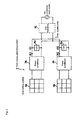
- FIG. 1 is a system configuration view of one embodiment of a solar energy generating system applied with the power conditioner according to the present invention.
- the solar energy generating system 1 is configured by a solar battery system 2 for converting the solar light to a direct current power; a power conditioner 3 for converting the direct power supplied from the solar battery system 2 via input terminals A, B to an alternating current synchronized with a system side power supply (commercial power supply) VAC and supplying the output power (active power) PX to a load resistance Rh via output terminals C, D; and a system side power supply (commercial power supply) VAC.
- a system side power supply commercial power supply
- VAC system side power supply
- the power conditioner 3 includes a power converting device 4 for converting the direct power supplied from the solar battery system 2 to the alternating power synchronized with the frequency and the alternating voltage of the system side (commercial power supply), and a controlling device 5 for controlling the operation of the power converting device 4.
- the controlling device 5 is configured on the basis of CPU (Central Processing Unit), and executes the output control, the frequency control, and the over current or over voltage control of the power converting device 4.
- CPU Central Processing Unit
- the controlling device 5 includes a single operation detecting means 6 for controlling the output current IX thereby fluctuating the output power (active power) PX and the output voltage (active voltage) VX to be output to the system side during the operation of the power conditioner 3 and measuring the line impedance value R1 on the system side based on the fluctuated active power PX and the active voltage VX, and thus determines the presence of abnormality (e.g., blackout) on the system side by measuring the active power PX and the active voltage VX and calculating the line impedance R1 from the measured active power PX and the active voltage VX.
- abnormality e.g., blackout
- the single operation detecting means 6 provides a set current I(S) at a predetermined interval in synchronization with the period of the alternating voltage on the system side as a command value and changes the output current IX thereby fluctuating the output voltage (active voltage) VX and the output power (active power) PX, measures the output current IX and the output voltage (active voltage) VX output from the power converting device 4, calculates the output power (active power) PX from the measured output current IX and the output voltage (active voltage) VX, and calculates the combined (parallel) impedance of the load resistance Rh and the line impedance R1 seen from the output terminals C, D based on the output current IX, output voltage (active voltage) VX and the output power (active power) PX.
- the active current, the active voltage, and the active power same as the power conditioner 3 in operation are output to the system side by executing the output current IX, the output voltage (active voltage) VX, and the output power (active power) PX in the region of the active current, the active voltage, and the active power, and thus the system side is not affected.
- the single operation detecting means 6 is configured by software process without adding additional components to the power conditioner 3.
- FIG. 2 is a waveform chart explaining one embodiment of the line impedance measurement according to the present invention.
- the single operation detecting means 6 outputs, in correspondence to one period T in which the output current IX is changed to the increased output current IXI (shown with solid line) with the level increased from one period T of the normal output current IXN (shown with broken line), the output voltage (active voltage) VX of one period T of the normal output voltage VXN (shown with broken line) and the increased output voltage VXI (shown with solid line), in synchronization with each other, from the power converting device 4 to the system side.
- the single operation detecting means 6 performs control so that the output voltage (active voltage) VX fluctuates in synchronization with the alternating power supply VAC on the system side.
- the abnormality (single operation) on the system side is detected based on the fluctuation impedance ⁇ Rp if the load resistance Rh does not fluctuate during the period T shown in FIG. 2 since the fluctuation impedance ⁇ Rp becomes the fluctuation of the line impedance R1.
- the single operation detecting means 6 since the single operation detecting means 6 according to the present invention fluctuates the active power PX and the active voltage VX to be output in synchronization with the alternating current VAC on the system side when fluctuating the active power PX and the active voltage VX to be output to the system side, the influence on the system side involved with the fluctuation of the active power PX and the active voltage VX is suppressed as much as possible, and the single operation detecting function can be operated during the operation of the power conditioner 3.
- FIG. 3 is a waveform chart explaining another embodiment of the line impedance measurement according to the present invention.
- the single operation detecting means 6 performs control so as to output the increased output current IXI (shown in solid line), in which the level of the output current IX is increased in correspondence to one period T of the normal output current IXN (shown in broken line) for one period T, and to output the decreased output current IXD (shown in solid line), in which the level is decreased, in the next period.
- the increased output current IXI (shown in solid line) which level is increased is output in the first period
- the decreased output current IXD (shown in solid line) which level is decreased is output in the next period
- the increased amount of level and the decreased amount of level are set equal.
- the average between the two periods thus becomes zero, and the influence on the system side due to the fluctuation of the output current IX cancels out.
- the fluctuation of the output current IX is set so as to occur in units of period and in a range from zero crossing to zero crossing, and so as to gradually change the level of the increased output current IXI (shown in solid line) and the decreased output current IXD (shown in solid line).
- the calculation of the fluctuation impedance ⁇ Rp is performed for the first period and the next period, respectively.
- the single operation detecting means is capable of averaging the fluctuation of the active power and the active voltage for one period or a plurality of periods and minimizing the influence on the system side of the power consumption since the fluctuation of the output power (active power) PX and the output voltage (active voltage) VX to be output to the system side is fluctuated from zero crossing to zero crossing.
- the single operation detecting means is capable of reducing the fluctuation of the active power and the active voltage and minimizing the influence on the system side involved in the fluctuation of the active power and the current voltage since the output power (active power) PX and the output voltage (active voltage) VX to be output to the system side is gradually fluctuated.
- the single operation detecting means is capable of calculating a stable line impedance value because the active power and the active voltage that are irregularly generated are not used in the calculation of the line impedance since the average processing is performed on the value around the time of fluctuation of the active power and the active voltage to be output to the system side and measurement is performed based on the average processed value when measuring the line impedance value on the system side.
- FIG. 4 is a waveform chart explaining another embodiment of the line impedance measurement according to the present invention.
- the single operation detecting means 6 performs control so as to output the increased output current IXI (shown in solid line) in which the level of the output current IX is increased in correspondence to one period T of the normal output current IXN (show in broken line) for one period T, and to alternately output the decreased output current IXD (shown in solid line) in which the level is decreased (inverted) by equal amount for the next period.
- the period average value ⁇ PAV of the power fluctuation amount of positive polarity is applied for one period, and the period average value ⁇ PAV of the power fluctuation amount of negative polarity is applied to another period for the calculation of the fluctuation impedance ⁇ Rp.
- the fluctuation impedance ⁇ Rp can thus be accurately calculated based on the period average value ⁇ PAV of the power fluctuation amount having different polarities.
- the single operation detecting means 6 is capable of preventing the active power and the active voltage from increasing, and of operating the single operation function while minimizing the fluctuation of the active power and the active voltage as much as possible since the active power PX and the active voltage VX to be output to the system side are alternately increased and decreased for every predetermined period so that the total amount of change of the active power PX and the active voltage VX is approximately zero.
- the power conditioner 3 includes a single operation detecting means 6 for changing the output current IX in synchronization with the period of the alternating voltage on the system side thereby fluctuating the active power PX and the active voltage VX to be output to the system side and measuring the line impedance value R1 on the system side based on the fluctuated active power PX and the active voltage VX, and thus the presence of abnormality on the system side is determined by measuring the active power and the active voltage and calculating the line impedance from the measured active power and the active voltage, and the single operation detecting function is realized with a simple configuration without particularly adding components.
- FIG. 5 is a system configuration view of another embodiment of a solar energy generating system applied with the power conditioner according to the present invention.
- the solar energy generating system 7 has two power conditioners, the power conditioner 3a connected to the solar battery system 2a and the power conditioner 3b connected to the solar battery system 2b, connected in parallel to one system side power supply (commercial power supply) VAC.
- VAC system side power supply
- the load resistance Ra and the load resistance Rb are connected to the power conditioner 3a and the power conditioner 3b, respectively, where the output current IX1 and the output voltage (active voltage) VX1 are supplied from the power conditioner 3a to the load resistance Ra, and the output current IX2 and the output voltage (active voltage) VX2 are supplied from the power conditioner 3b to the load resistance Rb.
- the output current IX1, the output voltage (active voltage) VX1, the output current IX2, and the output voltage (active voltage) VX2 are synchronized with the system side power supply (commercial power supply) VAC.
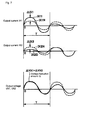
- FIG. 6 is a waveform chart of the output current/output voltage of one embodiment during the operation of the single operation detecting function of the power conditioner according to the present invention.
- the power conditioner 3a and the power conditioner 3b respectively outputs the same level of increased output current IX1I (shown in solid line) and increased output current IX2I (shown in solid line) synchronized with the normal output current IX1 N (shown in broken line) and the normal output current IX2N (shown in broken line), respectively, in the first period T, and outputs the same level of decreased output current IX1 D (shown in solid line) and the decreased output current IX2D (shown in solid line) synchronized with the normal output current IX1N (shown in broken line) and the normal output current IX2N (shown in solid line), respectively, in the next period T.
- FIG. 7 is a waveform chart of the output current/output voltage of another embodiment during the operation of the single operation detecting function of the power conditioner according to the present invention.
- the power conditioner 3a and the power conditioner 3b compare the line impedance value (fluctuation impedance ⁇ Rp) measured in the past and the line impedance (fluctuation impedance ⁇ Rp) currently measured, and when the current line impedance value (fluctuation impedance ⁇ Rp) is an impedance value (fluctuation impedance ⁇ Rp) greater than the past line impedance value (fluctuation impedance ⁇ Rp) or an impedance value (fluctuation impedance ⁇ Rp) smaller than the past line impedance value (fluctuation impedance ⁇ Rp), determines that the other device (power conditioner 3b) simultaneously operating in parallel with the self device (power conditioner 3a) is also measuring the line impedance and does not determine the current line impedance value as an abnormal value.
- the fluctuation impedance ⁇ Rp is not determined as an abnormal value when the fluctuation impedance ⁇ Rp arising from the current fluctuation amount ⁇ IX1 and the current fluctuation amount ⁇ IX2 of the output current IX1 and the output current IX2 or the voltage fluctuation amount ⁇ VX1 and the voltage fluctuation amount ⁇ VX2 of the output voltage (active voltage) VX1 and the output voltage (active voltage) VX2 is calculated with a deviation of greater than or equal to a constant value at the start of change (first period T) and the end of the change (next period T), as in the first period T and the next period T of FIG. 6, the single operation detecting functions of the power conditioner 3a and the power conditioner 3b are determined as simultaneously operating and the calculation result of the fluctuation impedance ⁇ Rp is deleted.
- the single operation detecting means 6 compares the line impedance value (fluctuation impedance ⁇ Rp) measured in the past and the line impedance (fluctuation impedance ⁇ Rp) currently measured, and when the current line impedance value is an impedance value greater than the past line impedance value, determines that the other device (power conditioner 3b) simultaneously operating in parallel with the self device (power conditioner 3a) is also measuring the line impedance value (fluctuation impedance ⁇ Rp) and does not determine the current line impedance value as the abnormal value, and thus the measurement result is deleted when the self device and the other device, which are operating in parallel, are simultaneously measuring the line impedance value, and the error detection of the single operation is prevented.
- the single operation detecting means 6 does not determine the line impedance value (fluctuation impedance ⁇ Rp) as an abnormal value when the deviation of the line impedance value (fluctuation impedance ⁇ Rp) at the start of change (first period T) and at the end of change (next period T) of the active power and the active voltage to be output to the system side is greater than or equal to a constant value, and thus when the self device (power conditioner 3a) and the other device (power conditioner 3b), which are operating in parallel, are simultaneously measuring the line impedance, the measurement result is deleted and the error detection of the single operation is prevented.
- a time difference is set to the measurement of the fluctuation impedance ⁇ Rp, so that the measurement of the fluctuation impedance ⁇ Rp is individually executed.
- a timer is arranged in the power conditioner 3a and the power conditioner 3b.
- the single operation detecting function of the power conditioner 3a is first operated, and after a predetermined time has elapsed since the single operation detecting function of the power conditioner 3a has stopped, the single operation detecting function of the power conditioner 3b is operated, thereby preventing both single operation detecting functions from simultaneously operating.
- the single operation detecting means 6 since the single operation detecting means 6 according to the preset invention performs the measurement of the line impedance with a predetermined time shift when the measurements of the line impedance value (fluctuation impedance ⁇ Rp) by the other device (power conditioner 3b) operating in parallel with the self device (power conditioner 3a) are synchronized, the self device and the other device can individually measure the line impedance value by setting a time difference when the self device and the other device are measuring the line impedance value in synchronization during parallel operation, and thus the single operation detecting function is properly operated even during parallel operation.
- the power conditioner according to the present invention determines the abnormality on the system side by changing the output current during operation to fluctuate the active output voltage and the active power and measuring the line impedance, and is applicable to the single operation detecting function of various power conditioners.
Landscapes
- Engineering & Computer Science (AREA)
- Power Engineering (AREA)
- Supply And Distribution Of Alternating Current (AREA)
- Dc-Dc Converters (AREA)
- Inverter Devices (AREA)
Applications Claiming Priority (1)
| Application Number | Priority Date | Filing Date | Title |
|---|---|---|---|
| JP2005071209A JP4353114B2 (ja) | 2005-03-14 | 2005-03-14 | パワーコンディショナ |
Publications (2)
| Publication Number | Publication Date |
|---|---|
| EP1703614A2 true EP1703614A2 (de) | 2006-09-20 |
| EP1703614A3 EP1703614A3 (de) | 2008-04-09 |
Family
ID=36609443
Family Applications (1)
| Application Number | Title | Priority Date | Filing Date |
|---|---|---|---|
| EP06004255A Withdrawn EP1703614A3 (de) | 2005-03-14 | 2006-03-02 | Leistungskonditionierer |
Country Status (3)
| Country | Link |
|---|---|
| EP (1) | EP1703614A3 (de) |
| JP (1) | JP4353114B2 (de) |
| CN (1) | CN100575966C (de) |
Cited By (3)
| Publication number | Priority date | Publication date | Assignee | Title |
|---|---|---|---|---|
| EP2725372A1 (de) * | 2012-10-26 | 2014-04-30 | Solantro Semiconductor Corp. | Stromerzeugungskomponentenkonnektivitätswiderstand |
| WO2014154619A1 (de) * | 2013-03-27 | 2014-10-02 | Siemens Aktiengesellschaft | Einspeisevorrichtung zum einspeisen von elektrischem strom in ein stromnetz sowie verfahren zum betreiben einer solchen einspeisevorrichtung |
| CN112068027A (zh) * | 2020-08-26 | 2020-12-11 | 华北电力大学 | 一种柔性直流输电交流系统短路比的识别方法 |
Families Citing this family (7)
| Publication number | Priority date | Publication date | Assignee | Title |
|---|---|---|---|---|
| JP5390262B2 (ja) * | 2009-05-27 | 2014-01-15 | 株式会社Nttファシリティーズ | 太陽光発電システムにおけるパワーコンディショナーの制御方法及び装置 |
| KR101027066B1 (ko) | 2009-10-20 | 2011-04-11 | 한국에너지기술연구원 | 전류 크기 변동에 따른 상관관계 기반의 단독운전 검출 방법 |
| US8466706B2 (en) * | 2010-08-17 | 2013-06-18 | Schneider Electric USA, Inc. | Solar combiner with integrated string current monitoring |
| JP5637234B2 (ja) * | 2013-03-15 | 2014-12-10 | オムロン株式会社 | 単独運転検出装置、パワーコンディショナ、分散型電源システム、プログラム、および単独運転検出方法 |
| JP5637235B2 (ja) * | 2013-03-15 | 2014-12-10 | オムロン株式会社 | 単独運転検出装置、パワーコンディショナ、分散型電源システム、プログラム、および単独運転検出方法 |
| JP5637236B2 (ja) * | 2013-03-15 | 2014-12-10 | オムロン株式会社 | 単独運転検出装置、パワーコンディショナ、分散型電源システム、プログラム、および単独運転検出方法 |
| WO2019012725A1 (ja) * | 2017-07-13 | 2019-01-17 | 三菱電機株式会社 | 電力変換装置、電力変換システム、および電力変換装置の運転方法 |
Family Cites Families (4)
| Publication number | Priority date | Publication date | Assignee | Title |
|---|---|---|---|---|
| JPH08130830A (ja) * | 1994-10-31 | 1996-05-21 | Nissin Electric Co Ltd | 分散電源の単独運転検出装置 |
| DE10006443B4 (de) * | 2000-02-14 | 2005-06-16 | Klaus-Wilhelm Köln | Verfahren zur Messung der Impedanz in Stromnetzen |
| US6545885B2 (en) * | 2000-03-13 | 2003-04-08 | Nissin Electric Co., Ltd. | Isolated operation prevention device for distributed power supply and interharmonic detection method |
| US6603290B2 (en) * | 2001-11-26 | 2003-08-05 | Visteon Global Technologies, Inc. | Anti-islanding detection scheme for distributed power generation |
-
2005
- 2005-03-14 JP JP2005071209A patent/JP4353114B2/ja not_active Expired - Lifetime
-
2006
- 2006-03-02 EP EP06004255A patent/EP1703614A3/de not_active Withdrawn
- 2006-03-07 CN CN200610009398A patent/CN100575966C/zh not_active Expired - Fee Related
Non-Patent Citations (1)
| Title |
|---|
| None |
Cited By (5)
| Publication number | Priority date | Publication date | Assignee | Title |
|---|---|---|---|---|
| EP2725372A1 (de) * | 2012-10-26 | 2014-04-30 | Solantro Semiconductor Corp. | Stromerzeugungskomponentenkonnektivitätswiderstand |
| US9267973B2 (en) | 2012-10-26 | 2016-02-23 | Solantro Semiconductor Corp. | Power generating component connectivity resistance |
| WO2014154619A1 (de) * | 2013-03-27 | 2014-10-02 | Siemens Aktiengesellschaft | Einspeisevorrichtung zum einspeisen von elektrischem strom in ein stromnetz sowie verfahren zum betreiben einer solchen einspeisevorrichtung |
| CN112068027A (zh) * | 2020-08-26 | 2020-12-11 | 华北电力大学 | 一种柔性直流输电交流系统短路比的识别方法 |
| CN112068027B (zh) * | 2020-08-26 | 2023-01-17 | 华北电力大学 | 一种柔性直流输电交流系统短路比的识别方法 |
Also Published As
| Publication number | Publication date |
|---|---|
| JP4353114B2 (ja) | 2009-10-28 |
| CN100575966C (zh) | 2009-12-30 |
| EP1703614A3 (de) | 2008-04-09 |
| JP2006254664A (ja) | 2006-09-21 |
| CN1834666A (zh) | 2006-09-20 |
Similar Documents
| Publication | Publication Date | Title |
|---|---|---|
| US4177389A (en) | Power supply system with two regulated power supply devices connected in parallel at an output | |
| JP5352743B2 (ja) | 分散型電源システム及びその制御方法 | |
| JP4820461B2 (ja) | 分散型電源システム | |
| EP1703614A2 (de) | Leistungskonditionierer | |
| US8001392B2 (en) | Battery load allocation in parallel-connected uninterruptible power supply systems | |
| EP3091635B1 (de) | Leistungsduplikationsvorrichtung für ein hvdc-system und steuerungsverfahren dafür | |
| US20140119084A1 (en) | AC Input Voltage Detection Circuit and AC/DC Power Source | |
| WO2019082431A1 (ja) | 系統連系蓄電システム及び電流センサの取り付け異常検出方法 | |
| TW201500902A (zh) | 機櫃與其電源控制方法 | |
| JP6489899B2 (ja) | 分散型電源装置 | |
| CN102244411A (zh) | 一种ups并机系统及其并机方法 | |
| GB2418992A (en) | Rechargeable Powering System For Electricity Meter | |
| JP2019213387A (ja) | 分散型電源ユニット、その制御方法及び異常判定方法 | |
| US20150338860A1 (en) | Control electronics for a process device and method for operation therefor | |
| JP6611899B2 (ja) | 分散型電源装置 | |
| JP7844761B1 (ja) | 無停電電源装置 | |
| JPH01163614A (ja) | センサ信号処理方法 | |
| JP5822297B2 (ja) | 電源システム、サーバシステム、及び電源システムの電力制御方法 | |
| TWI482395B (zh) | 機櫃與其電源控制方法 | |
| JPH08130838A (ja) | 蓄電池監視装置 | |
| US20250210960A1 (en) | Method for detecting arcing, inverter and photovoltaic system | |
| US20250068196A1 (en) | Method and apparatus for identifying proper regulation method based on average voltage change between tap steps for voltage regulators | |
| JP2006223042A (ja) | インバータシステムの並列運転装置及びその並列運転方法 | |
| CN109936168A (zh) | 一种逆变器及其运行方法和控制器 | |
| JP4737095B2 (ja) | 単独運転検出装置及びその同期方法 |
Legal Events
| Date | Code | Title | Description |
|---|---|---|---|
| PUAI | Public reference made under article 153(3) epc to a published international application that has entered the european phase |
Free format text: ORIGINAL CODE: 0009012 |
|
| AK | Designated contracting states |
Kind code of ref document: A2 Designated state(s): AT BE BG CH CY CZ DE DK EE ES FI FR GB GR HU IE IS IT LI LT LU LV MC NL PL PT RO SE SI SK TR |
|
| AX | Request for extension of the european patent |
Extension state: AL BA HR MK YU |
|
| PUAL | Search report despatched |
Free format text: ORIGINAL CODE: 0009013 |
|
| RIC1 | Information provided on ipc code assigned before grant |
Ipc: H02J 3/38 20060101ALI20080226BHEP Ipc: H02J 3/40 20060101AFI20060707BHEP |
|
| AK | Designated contracting states |
Kind code of ref document: A3 Designated state(s): AT BE BG CH CY CZ DE DK EE ES FI FR GB GR HU IE IS IT LI LT LU LV MC NL PL PT RO SE SI SK TR |
|
| AX | Request for extension of the european patent |
Extension state: AL BA HR MK YU |
|
| 17P | Request for examination filed |
Effective date: 20080930 |
|
| 17Q | First examination report despatched |
Effective date: 20081030 |
|
| AKX | Designation fees paid |
Designated state(s): DE FR GB IT |
|
| STAA | Information on the status of an ep patent application or granted ep patent |
Free format text: STATUS: THE APPLICATION IS DEEMED TO BE WITHDRAWN |
|
| 18D | Application deemed to be withdrawn |
Effective date: 20161001 |