EP1703622B1 - Moteur asynchrone hybride - Google Patents
Moteur asynchrone hybride Download PDFInfo
- Publication number
- EP1703622B1 EP1703622B1 EP06000306A EP06000306A EP1703622B1 EP 1703622 B1 EP1703622 B1 EP 1703622B1 EP 06000306 A EP06000306 A EP 06000306A EP 06000306 A EP06000306 A EP 06000306A EP 1703622 B1 EP1703622 B1 EP 1703622B1
- Authority
- EP
- European Patent Office
- Prior art keywords
- rotary shaft
- rotor portion
- permanent magnet
- reverse rotation
- motor
- Prior art date
- Legal status (The legal status is an assumption and is not a legal conclusion. Google has not performed a legal analysis and makes no representation as to the accuracy of the status listed.)
- Expired - Lifetime
Links
Images




Classifications
-
- H—ELECTRICITY
- H02—GENERATION; CONVERSION OR DISTRIBUTION OF ELECTRIC POWER
- H02K—DYNAMO-ELECTRIC MACHINES
- H02K17/00—Asynchronous induction motors; Asynchronous induction generators
- H02K17/02—Asynchronous induction motors
- H02K17/30—Structural association of asynchronous induction motors with auxiliary electric devices influencing the characteristics of the motor or controlling the motor, e.g. with impedances or switches
-
- H—ELECTRICITY
- H02—GENERATION; CONVERSION OR DISTRIBUTION OF ELECTRIC POWER
- H02K—DYNAMO-ELECTRIC MACHINES
- H02K11/00—Structural association of dynamo-electric machines with electric components or with devices for shielding, monitoring or protection
- H02K11/20—Structural association of dynamo-electric machines with electric components or with devices for shielding, monitoring or protection for measuring, monitoring, testing, protecting or switching
- H02K11/21—Devices for sensing speed or position, or actuated thereby
-
- H—ELECTRICITY
- H02—GENERATION; CONVERSION OR DISTRIBUTION OF ELECTRIC POWER
- H02K—DYNAMO-ELECTRIC MACHINES
- H02K16/00—Machines with more than one rotor or stator
- H02K16/02—Machines with one stator and two or more rotors
-
- H—ELECTRICITY
- H02—GENERATION; CONVERSION OR DISTRIBUTION OF ELECTRIC POWER
- H02K—DYNAMO-ELECTRIC MACHINES
- H02K7/00—Arrangements for handling mechanical energy structurally associated with dynamo-electric machines, e.g. structural association with mechanical driving motors or auxiliary dynamo-electric machines
- H02K7/10—Structural association with clutches, brakes, gears, pulleys or mechanical starters
- H02K7/118—Structural association with clutches, brakes, gears, pulleys or mechanical starters with starting devices
- H02K7/1185—Structural association with clutches, brakes, gears, pulleys or mechanical starters with starting devices with a mechanical one-way direction control, i.e. with means for reversing the direction of rotation of the rotor
-
- H—ELECTRICITY
- H02—GENERATION; CONVERSION OR DISTRIBUTION OF ELECTRIC POWER
- H02K—DYNAMO-ELECTRIC MACHINES
- H02K21/00—Synchronous motors having permanent magnets; Synchronous generators having permanent magnets
- H02K21/12—Synchronous motors having permanent magnets; Synchronous generators having permanent magnets with stationary armatures and rotating magnets
- H02K21/14—Synchronous motors having permanent magnets; Synchronous generators having permanent magnets with stationary armatures and rotating magnets with magnets rotating within the armatures
Definitions
- the present invention relates to a hybrid induction motor, and particularly, to a hybrid induction motor having a reverse rotation preventing function.
- an induction motor includes a stator forming a rotating magnetic field and a rotor unit rotatably disposed with an air gap from the stator.
- the so-called hybrid induction motor which has a permanent magnet interposed between the stator and the rotor unit has been widely used so as to enhance operational efficiency and reduce power consumption.
- Figure 1 is a sectional view of a conventional hybrid induction motor
- Figure 2 is a sectional view of a cage rotor portion taken along line II-II of Figure 1 .
- a hybrid induction motor includes: a housing 151, a cover 155, a stator 110 and a rotor coupling body 120 rotatably received in the stator 110.
- the housing 151 is a container having an opening at its front side, and the cover 155 for covering the opening is coupled with the front side of the housing 151.
- Bearing receiving portions 153 and 157 capable of receiving bearings 125, respectively, are formed at a rear side of the housing 151 and a center portion of the front side of the cover 155.
- the stator 110 includes a stator core portion 111 and a stator coil portion 115.
- the stator core portion 111 is formed by insulating/laminating a plurality of electric steel sheets, each having a rotor receiving hole 112 and a slot 113 formed thereon.
- the stator coil portion 115 winds around the stator core portion 111 and generates a rotating magnetic field.
- the rotor coupling body 120 includes a rotary shaft 121, a cage rotor portion 131 integrally coupled to a circumference of the rotary shaft 121 so as to be rotatable, and a permanent magnet rotor portion 141 coupled to a circumference of the cage rotor portion 131 with a certain air gap so as to be rotatable with respect to the rotary shaft 121.
- the bearings 125 are insertedly installed in the bearing receiving portions 153 and 157, respectively, and support the rotary shaft 121 so as to be rotatable.
- a fan 150 is coupled to a front end of the rotary shaft 121.
- the permanent magnet rotor portion 141 includes a permanent magnet 142, and a magnet support portion 144 having one side coupled with the rotary shaft 121 so as to support the permanent magnet 142 to be rotatable and the other side integrally coupled with the permanent magnet 142.
- the cage rotor portion 131 includes: a rotor core portion 133 formed by insulating/laminating electric steel plates, each having a shaft hole 134 at its center and a slot 135 along a circumferential direction; a conductor bar 137 disposed inside each slot 135; and an end ring portion 139 formed to electrically connect both ends of the conductor bar 137 to each other.
- a rotating magnetic field is formed if power is supplied to the stator 110.
- the permanent magnet rotor portion 141 performs relative rotation to the rotary shaft 121 so as to correspond to the rotating magnetic field and is synchronized.
- the conventional hybrid induction motor has a problem that the permanent magnet rotor portion 141 and the cage rotor portion 131 rotate reversibly because of a voltage phase at the first power input, an influence of an unbalanced rotating magnetic field and initial polarity of a magnet or the like.
- the conventional hybrid induction motor requires for a separate reverse rotation detecting and blocking circuit (not illustrated) to thusly increase the manufacturing cost.
- EP 1 455 435 A2 relates to a single phase induction motor further comprising a permanent magnet unit, wherein the single phase induction motor comprises a stator installed at an inner circumferential surface of a motor housing, comprising a stator core on which a plurality of coils are wound, a rotor rotatably installed at a center of the stator and provided with a shaft at a center thereof, and a permanent magnetic unit in the air gap between stator and rotor and able to rotate around the shaft.
- an object of the present invention is to provide a hybrid induction motor implementing low manufacturing cost and capable of preventing reverse rotation.
- a hybrid induction motor comprising: a housing; a stator installed in the housing and having a stator core portion and a stator coil portion; a rotor coupling body having a rotary shaft rotatably installed at the housing, a cage rotor portion rotating integrally with the rotary shaft, and a permanent magnet rotor portion coupled to a circumference of the cage rotor portion with a certain air gap so as to be freely rotatable with respect to the rotary shaft; and a reverse rotation preventing switch, when the rotary shaft rotates reversibly, coming in contact with the permanent magnet rotor portion and cutting off power being supplied to the stator coil portion, wherein the rotor coupling body generates thrust by which the permanent magnet rotor portion comes in contact with the reverse rotation preventing switch when the rotary shaft rotates reversibly.
- Figure 3 is a sectional view of a hybrid induction motor in accordance with first embodiment of the present invention
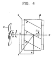
- Figure 4 is a view illustrating thrust operation during reverse rotation of a rotary shaft
- Figure 5 is a view illustrating the operation of a reverse rotation preventing switch of Figure 3 .
- a hybrid induction motor in accordance with the first embodiment includes a housing 51, a stator 10, a rotor coupling body 31 and a reverse rotation preventing switch 61.
- the housing 51 is a container having an opening at its front side, and a cover 55 for covering the opening is coupled to the front side.
- Bearing receiving portions 53 and 57 capable of receiving bearings 23, respectively, are formed at a rear side of the housing 51 and the center portion of a front side of the cover 55, respectively.
- the stator 10 includes a stator core portion 11 and a stator coil portion 15.
- the stator core portion 11 is formed by insulating/laminating a plurality of electric steel plates, each of which has a rotor receiving hole 12 and a slot 13.
- the stator coil portion 15 winds around the stator core portion 11 and generates a rotating magnetic field.
- the rotor coupling body 20 includes a rotary shaft 21, a cage rotor portion 31 and a permanent magnet rotor portion 41.
- a fan 27 rotating integrally with the rotary shaft 21 is coupled to a front end portion of the rotary shaft 21.
- the bearings 23 are insertedly installed in the bearing receiving portions 53 and 57, respectively, and support the rotary shaft 21 so as to be rotatable.
- the cage rotor portion 31 is coupled with the rotary shaft 21 so as to be rotatable integrally with the rotary shaft 21, and includes a rotor core 33, a conductor bar 37 and an end ring portion 39.
- the rotor core 33 includes a plurality of slots 35 each of which has a shaft hole 34 into which the rotary shaft 21 is inserted at its center and which are disposed separately from each other.
- the conductor bar 37 penetrates the rotor core 33.
- a plurality of conductor bars 37 are inclined downwardly toward the right from the left to have a skew angle as much as O with respect to the rotary shaft 21.
- the conductor bar 37 has the skew angle as much as O with respect to the rotary shaft 21 to thusly generate a reaction force (-F2) to allow the permanent magnet rotor portion 41 to move in a direction of the arrow A along a direction of an axis (X).
- torque (F) is generated in a direction perpendicular to the skew angle of the conductor bar 37.
- the torque (F) can disassemble into torque (F1) rotating the cage rotor portion 31 and thrust (F2) moving the cage rotor portion 31 in a direction of the arrow B along direction of the axis (X).
- the cage rotor portion 31 is integrally fixed and coupled with the rotary shaft 21, and the permanent magnet rotor portion 41 is movably coupled with the rotary shaft 21 along the direction of the axis (X). Accordingly, the thrust (F2) acts as the reaction force (-F2) by which the permanent magnet rotor portion 41 performs relative movement along the direction of the axis (X). That is, while the cage rotor portion 31 is fixed, only the permanent magnet rotor portion 41 is moved in the direction of the arrow A, that is, in a direction where it gets far from the cage rotor portion 31.
- the end ring portion 39 connects both ends of the conductor bar 37 to each other.
- the end ring portion 39 and the conductor bar 37 are integrally connected with each other by a die casting.
- the permanent magnet rotor portion 41 is coupled to a circumference of the cage rotor portion 31 with a certain air gap so as to be freely rotatable with respect to the rotary shaft 21, and includes a permanent magnet 43, a bearing 45 and a magnet support portion 44.
- the permanent magnet 43 has a cylindrical shape, forms magnet poles different from each other along a circumferential direction, and is coupled to one side of the magnet support portion 44.
- the bearing 45 is coupled with the rotary shaft 21 so as to be freely rotatable with respect to the rotary shaft 21 and movable in the direction of the arrow A or the arrow B along the direction of the axis (X).
- the magnet support portion 44 has one side integrally coupled with the bearing 45 and the other side supporting the permanent magnet 142 so as to be rotatable.
- a stopper 25 is installed at the inside of the permanent magnet rotor portion 41.
- the reverse rotation preventing switch 61 is installed at the right side of the inside of the housing 51, and includes a body 63, a operation pin 65 and a spring 67.
- the reverse rotation preventing switch 61 when the rotary shaft 21 rotates reversibly in a direction of the arrow R, comes in contact with the permanent magnet rotor portion 41 and cuts off power being supplied to the stator coil portion 15 (refer to Figure 5 ).
- the body 63 forms a receiving space therein.
- the operation pin 65 connects or separates a point of contact 64 by protruding or retracting with respect to the body 63, whereby power is supplied or cut off to the stator coil portion 15.
- the spring 67 is installed at the rear side of the operation pin 65, and pressurizes the operation pin 65 to protrude the operation pin 65 outside the body 63.
- the torque (F) can disassemble into torque (F1) rotating the cage rotor portion 31 and thrust (F2) allowing the cage rotor portion 31 to move in the direction of the arrow B along the direction of the axis (X).
- the cage rotor portion 31 is integrally fixed and coupled with the rotary shaft 21, and the permanent magnet rotor portion 41 is coupled so as to be movable with respect to the rotary shaft 21 along the direction of the axis (X). Accordingly, the thrust (F2) acts as a reaction force (-F2) by which the permanent magnet rotor portion 41 is moved in the direction of the arrow A along the direction of the axis (X). That is, while the cage rotor portion 31 is fixed, only the permanent magnet rotor portion 41 is moved in the direction of the arrow A, that is, in the direction where it gets far from the cage rotor portion 31.
- one side of the moved permanent magnet rotor portion 41 pressurizes the operation pin 65 of the reverse rotation preventing switch 61.
- the pressurized operation pin 65 retracts inside the body 63 and separates the point of the contact 64, thereby cutting off power being supplied to the stator coil portion 15.
- the reaction force (-F2) applied to the permanent magnet rotor portion 41 is released. Therefore, the permanent magnet rotor portion 41 is moved in the direction of the arrow B and returned to an initial position.
- the stopper 25 prevents the permanent magnet rotor portion 41 from moving in the direction of the arrow B along the direction of the axis (X) of the rotary shaft 21 more than a certain distance.
- the reverse rotation preventing switch 61 is returned to the initial position by a restoring force of the spring 67.
- the operation pin 65 protrudes outside the body 63, connects the point of contact 64 and therefore supplies power to the stator coil portion 15.
- FIG. 6 is a sectional view of a hybrid induction motor in accordance with the second embodiment of the present invention
- Figure 7 is a view illustrating thrust operation during reverse rotation of a rotary shaft of Figure 6
- Figure 8 is a view illustrating the operation of a reverse rotation preventing switch of Figure 6 .
- the same reference numerals are given to the same construction as the aforementioned and illustrated construction for the purpose of simplicity in description for the drawings, and detailed descriptions therefor will be omitted.
- a difference between the first embodiment and the second embodiment lies in a direction of a skew angle of a conductor bar 38, a location of a reverse rotation preventing switch 61 and a location of a stopper 25. Since the remaining construction is the same, a detailed description therefor will be omitted.
- the conductor bar 38 of the second embodiment is inclined downwardly toward the left side from the right side to have a skew angle as much as ⁇ with respect to a rotary shaft 21.
- the conductor bar 38 has the skew angle as much as ⁇ with respect to the rotary shaft 21 to thusly generate a reaction force (-F2) by which the permanent magnet rotor portion 41 is moved in a direction of the arrow B along a direction of an axis (X).
- torque (F) is generated in a direction perpendicular to the skew angle of the conductor bar 38.
- the torque (F) can disassemble into torque (F1) rotating a cage rotor portion 31 and thrust (F2) allowing the cage rotor portion 31 to move in a direction of the arrow A along the direction of the axis (X).
- the cage rotor portion 31 is integrally fixed and coupled with the rotary shaft 21, while the permanent magnet rotor potion 41 is coupled so as to be movable with respect to the rotary shaft 21 along the direction of the axis (X).
- the thrust (F2) acts as the reaction force (-F2) by which the permanent magnet rotor portion 41 performs relative along the direction of the axis (X). That is, while the cage rotor portion 31 is fixed, only the permanent magnet rotor portion 41 is moved in the direction of the arrow B, that is, in a direction where it gets far from the cage rotor portion 31.
- the stopper 25 of the first embodiment is installed at the inside of the permanent magnet rotor portion 41
- the stopper 25 of the second embodiment is installed at the outside of the permanent magnet rotor portion 41.
- a reverse rotation preventing switch 61 is installed at the left side of the inside of the housing 51 and includes a body 63, an operation pin 65 and a spring 67.
- the reverse rotation preventing switch 61 when the rotary shaft 21 rotates reversibly in the direction of the arrow R, comes in contact with the permanent magnet rotor portion 41 and cuts off power being supplied to the stator coil portion 15.
- the torque (F) can disassemble into torque (F1) rotating the cage rotor portion 31 and thrust (F2) allowing the cage rotor potion 31 to move in the direction of the arrow A along the direction of the axis (X).
- the cage rotor portion 31 is integrally fixed and coupled with the rotary shaft 21, and the permanent magnet rotor portion 41 is coupled so as to be movable with respect to the rotary shaft 21 along the direction of the axis (X). Accordingly, the thrust (F2) acts as a reaction force (-F2) by which the permanent magnet rotor portion 41 to move in the direction of the arrow B along the direction of the axis (X). That is, while the cage rotor portion 31 is fixed, only the permanent magnet rotor portion 41 moves in the direction of the arrow B, that is, in the direction where it gets close to the cage rotor portion 31.
- one side of the moved permanent magnet rotor portion 41 pressurizes the operation pin 65 of the reverse rotation preventing switch 61.
- the pressurized operation pin 65 retracts inside the body 63 and separates a point of contact 64, thereby cutting off power being supplied to the stator coil portion 15.
- the reaction force (-F2) applied to the permanent magnet rotor potion 41 is released. Therefore, the permanent magnet rotor portion 41 is moved in the direction of the arrow A and returned to an initial position.
- the stopper 25 prevents the permanent magnet rotor portion 41 from moving in the direction of the arrow A along the direction of the axis (X) of the rotary shaft 21 more than a certain distance.
- the reverse rotation preventing switch 61 is returned to its initial position by a restoring force of the spring 67.
- the operation pin 65 protrudes outside the body 63 and connects the point of contact 64, thereby supplying power to the stator coil portion 15.
- the conductor bars 37 and 38 have a skew angle as much as O with respect to the rotary shaft 21 in order to generate the reaction force (-F2) by which the permanent magnet rotor portion 41 moves along the direction of the axis (X).
- the conductor bars 37 and 38 can be disposed at the rotary shaft 21 without the skew angle and each magnetic pole of the permanent magnet rotor portion 41 has a certain skew angle.
- a separate reverse rotation detecting and blocking circuit (not illustrated) for preventing reverse rotation is not required and therefore the manufacturing cost for the hybrid induction motor is reduced.
- the reverse rotation can be prevented with only simple instrumental construction to thusly enhance reliability.
Landscapes
- Engineering & Computer Science (AREA)
- Power Engineering (AREA)
- Microelectronics & Electronic Packaging (AREA)
- Permanent Magnet Type Synchronous Machine (AREA)
- Induction Machinery (AREA)
- Iron Core Of Rotating Electric Machines (AREA)
Claims (8)
- Moteur asynchrone hybride comprenant :un carter (51) ;un stator (10) installé dans le carter (51) et possédant une partie de noyau de stator (11) et une partie de bobine de stator (15) ;un corps d'accouplement de rotor (20) possédant un arbre rotatif (21) installé de manière rotative au niveau du carter (51), une partie de rotor à cage (31) tournant de manière solidaire avec l'arbre rotatif (21), et une partie de rotor à aimant permanent (41) située entre le stator (10) et la partie de rotor à cage (31) et couplée à une circonférence de la partie de rotor à cage (31) avec un entrefer donné de manière à pouvoir tourner librement vis-à-vis de l'arbre rotatif (21) et se déplacer librement le long de l'arbre rotatif (21) ;et un commutateur empêchant la rotation inverse (61) ;dans lequel la partie de rotor à cage (31) comprend des barres conductrices (37) possédant un angle d'inclinaison (Θ) par rapport à l'arbre rotatif (21),dans lequel en cas de rotation inverse de l'arbre rotatif (21) une force de réaction perpendiculaire à l'angle d'inclinaison (Θ) des barres conductrices (37) est générée pour permettre à la partie de rotor à aimant permanent (41) de se déplacer le long de l'arbre rotatif (21), etdans lequel le déplacement de la partie de rotor à aimant permanent (41) le long de l'arbre rotatif (21) actionne le commutateur empêchant la rotation inverse (61) de telle sorte que le commutateur empêchant la rotation inverse (61) coupe l'alimentation étant délivrée à la partie de bobine de stator (15).
- Moteur selon la revendication 1, dans lequel la partie de rotor à cage (31) comprend :un noyau de rotor (33) possédant un trou d'arbre (34) dans lequel l'arbre rotatif (21) est inséré ; etune partie de bague d'extrémité (39) reliant les deux parties d'extrémités de la barre conductrice (37) l'une à l'autre.
- Moteur selon la revendication 1, dans lequel la partie de rotor à aimant permanent (41) comprend :un palier (23) couplé de manière rotative et déplaçable avec l'arbre rotatif (21) ;une partie de support d'aimant (44) couplée de manière solidaire avec le palier (23) ; etun aimant permanent (43) couplé à un côté de la partie de support d'aimant (44).
- Moteur selon la revendication 1, dans lequel le commutateur empêchant la rotation inverse (61) comprend :un corps (63) ;une tige opérationnelle (62) installée dans le corps (63) et mise sous pression par la partie de rotor à aimant permanent (41) quand l'arbre rotatif (21) tourne dans le sens inverse ; etun ressort (67) destiné à mettre sous pression la tige opérationnelle (65) pour faire dépasser la tige opérationnelle (65) hors du corps (63).
- Moteur selon la revendication 2, dans lequel la barre conductrice (37) est inclinée vers le bas en direction du côté droit depuis le côté gauche pour présenter un angle d'inclinaison (Θ) jusqu'à Θ par rapport à l'arbre rotatif (21) et le commutateur empêchant la rotation inverse (61) est installé au niveau du côté droit de l'intérieur du carter (51).
- Moteur selon la revendication 5, comprenant en outre :une butée (25) installée dans la partie de rotor à aimant permanent (41).
- Moteur selon la revendication 2, dans lequel la barre conductrice (37) est inclinée vers le bas en direction du côté gauche depuis le côté droit pour présenter un angle d'inclinaison (Θ) jusqu'à Θ par rapport à l'arbre rotatif (21) et le commutateur empêchant la rotation inverse (61) est installé au niveau du côté droit de l'intérieur du carter (51).
- Moteur selon la revendication 7, comprenant en outre :une butée (25) installée à l'extérieur de la partie de rotor à aimant permanent (41).
Applications Claiming Priority (1)
| Application Number | Priority Date | Filing Date | Title |
|---|---|---|---|
| KR1020050021567A KR100619782B1 (ko) | 2005-03-15 | 2005-03-15 | 역회전 방지기능을 구비한 하이브리드 인덕션모터 |
Publications (2)
| Publication Number | Publication Date |
|---|---|
| EP1703622A1 EP1703622A1 (fr) | 2006-09-20 |
| EP1703622B1 true EP1703622B1 (fr) | 2008-07-09 |
Family
ID=35655524
Family Applications (1)
| Application Number | Title | Priority Date | Filing Date |
|---|---|---|---|
| EP06000306A Expired - Lifetime EP1703622B1 (fr) | 2005-03-15 | 2006-01-09 | Moteur asynchrone hybride |
Country Status (6)
| Country | Link |
|---|---|
| US (1) | US7459814B2 (fr) |
| EP (1) | EP1703622B1 (fr) |
| JP (1) | JP2006262693A (fr) |
| KR (1) | KR100619782B1 (fr) |
| CN (1) | CN1835348A (fr) |
| DE (1) | DE602006001669D1 (fr) |
Families Citing this family (14)
| Publication number | Priority date | Publication date | Assignee | Title |
|---|---|---|---|---|
| KR100619751B1 (ko) * | 2004-10-23 | 2006-09-13 | 엘지전자 주식회사 | 셰이딩 코일형 단상 동기/유도 전동기 |
| KR20070071202A (ko) * | 2005-12-29 | 2007-07-04 | 엘지전자 주식회사 | 하이브리드 인덕션 모터의 속도 가변장치 및 방법 |
| KR101198232B1 (ko) | 2006-03-17 | 2012-11-07 | 엘지전자 주식회사 | 하이브리드 인덕션모터 |
| CN100438278C (zh) * | 2006-09-14 | 2008-11-26 | 湖南大学 | 复合式电机 |
| US20080150400A1 (en) * | 2006-12-21 | 2008-06-26 | James Robert Crowell | Electric machines, rotors, and rotor cages having reduced noise characteristics |
| US8358046B2 (en) | 2007-12-28 | 2013-01-22 | Platon Mihai C | Hybrid electric power system with distributed segmented generator/motor |
| DE102009047502A1 (de) * | 2009-12-04 | 2011-06-09 | Robert Bosch Gmbh | Elektromotor |
| JP5835215B2 (ja) * | 2010-05-17 | 2015-12-24 | 日立金属株式会社 | カップリング装置 |
| EP2509199A1 (fr) * | 2011-04-08 | 2012-10-10 | Grundfos Management A/S | Rotor |
| CN102386733B (zh) * | 2011-11-04 | 2013-10-09 | 国电联合动力技术有限公司 | 一种混合型中速永磁风力发电机及其机组 |
| CN105846622B (zh) * | 2016-04-05 | 2018-04-17 | 江苏大学 | 具有缓速和差速功能纯电动汽车用双转子电机及工作方法 |
| KR200487718Y1 (ko) * | 2018-03-20 | 2018-10-24 | 이태영 | 방충창용 환풍장치 |
| CN110548607A (zh) * | 2019-08-30 | 2019-12-10 | 贾力 | 节能环保有机垃圾处理机 |
| CN114884296A (zh) * | 2022-05-25 | 2022-08-09 | 珠海格力电器股份有限公司 | 一种电机及制造方法 |
Family Cites Families (8)
| Publication number | Priority date | Publication date | Assignee | Title |
|---|---|---|---|---|
| US3501656A (en) * | 1969-01-07 | 1970-03-17 | American Mach & Foundry | Rotor construction with directional control for a synchronous a.c. motor |
| US3821567A (en) * | 1973-02-09 | 1974-06-28 | Mallory & Co Inc P R | Means correcting a wrong way directional rotation of a rotating member |
| US4177395A (en) * | 1977-12-19 | 1979-12-04 | Rotork Limited | Actuators |
| DE3420370A1 (de) * | 1984-01-02 | 1985-07-11 | Robert Bosch Gmbh, 7000 Stuttgart | Induktionsmotor |
| JPS60190141A (ja) | 1984-03-08 | 1985-09-27 | Matsushita Electric Ind Co Ltd | 永久磁石式同期電動機の一方向回転装置 |
| US5117143A (en) * | 1991-03-22 | 1992-05-26 | Electric Motors And Specialities, Inc. | Anti-windmilling motor |
| JPH11178277A (ja) | 1997-12-10 | 1999-07-02 | Bunka Shutter Co Ltd | ブレーキ付モータ及び該モータを有する開閉体装置 |
| US7239057B2 (en) * | 2003-03-04 | 2007-07-03 | Lg Electronics Inc. | Single phase induction motor |
-
2005
- 2005-03-15 KR KR1020050021567A patent/KR100619782B1/ko not_active Expired - Fee Related
-
2006
- 2006-01-05 US US11/325,503 patent/US7459814B2/en not_active Expired - Fee Related
- 2006-01-09 DE DE602006001669T patent/DE602006001669D1/de not_active Expired - Lifetime
- 2006-01-09 EP EP06000306A patent/EP1703622B1/fr not_active Expired - Lifetime
- 2006-03-13 CN CNA2006100678231A patent/CN1835348A/zh active Pending
- 2006-03-15 JP JP2006071216A patent/JP2006262693A/ja not_active Withdrawn
Also Published As
| Publication number | Publication date |
|---|---|
| US7459814B2 (en) | 2008-12-02 |
| KR100619782B1 (ko) | 2006-09-06 |
| DE602006001669D1 (de) | 2008-08-21 |
| US20060208597A1 (en) | 2006-09-21 |
| EP1703622A1 (fr) | 2006-09-20 |
| JP2006262693A (ja) | 2006-09-28 |
| CN1835348A (zh) | 2006-09-20 |
Similar Documents
| Publication | Publication Date | Title |
|---|---|---|
| EP1703622B1 (fr) | Moteur asynchrone hybride | |
| US11646610B2 (en) | Stator and motor comprising same | |
| KR100619769B1 (ko) | 역회전 방지기능을 구비한 하이브리드 타입 인덕션모터 | |
| KR102145758B1 (ko) | 전식 방지 구조를 갖는 비엘디씨 모터 | |
| CN102904400A (zh) | 横向开关磁阻电机 | |
| US20180175570A1 (en) | Bus bar unit and rotary electric machine having the same | |
| JP2010141993A (ja) | 回転電機用マグネットホルダ | |
| US11888355B2 (en) | Rotor and motor including same | |
| JP2010022088A (ja) | 磁石回転型回転電機 | |
| EP1202430A1 (fr) | Moteur sans balais | |
| US7755245B2 (en) | Synchronous motor with permanent-magnet rotor | |
| US20150115765A1 (en) | Motor and method of winding stator coil | |
| EP1835601B1 (fr) | Moteur à induction hybride | |
| US11658530B2 (en) | Modular brushless DC (BLDC) motor construction | |
| KR102655249B1 (ko) | 모터 및 이를 포함하는 전동식 조향장치 | |
| KR100619783B1 (ko) | 역회전 방지기능을 구비한 하이브리드 인덕션모터 | |
| JP2000312447A (ja) | 永久磁石ロータ及びモータ | |
| JP2010166661A (ja) | 回転電機、回転電機の駆動方法及び、圧縮機 | |
| JP3985964B2 (ja) | ディテントトルク発生手段を有するステータと同ステータを備えた軸方向空隙型ブラシレスモータ | |
| JP2010093879A (ja) | 回転電機 | |
| KR20210149580A (ko) | 코깅리스 코어리스 bldc 모터 | |
| KR100652592B1 (ko) | 하이브리드 인덕션모터 | |
| KR20180068014A (ko) | 로터 및 이를 포함하는 모터 | |
| KR20210027885A (ko) | 모터 | |
| KR100672382B1 (ko) | 하이브리드 인덕션 모터 |
Legal Events
| Date | Code | Title | Description |
|---|---|---|---|
| PUAI | Public reference made under article 153(3) epc to a published international application that has entered the european phase |
Free format text: ORIGINAL CODE: 0009012 |
|
| 17P | Request for examination filed |
Effective date: 20060109 |
|
| AK | Designated contracting states |
Kind code of ref document: A1 Designated state(s): AT BE BG CH CY CZ DE DK EE ES FI FR GB GR HU IE IS IT LI LT LU LV MC NL PL PT RO SE SI SK TR |
|
| AX | Request for extension of the european patent |
Extension state: AL BA HR MK YU |
|
| AKX | Designation fees paid |
Designated state(s): DE FR GB |
|
| 17Q | First examination report despatched |
Effective date: 20070507 |
|
| GRAP | Despatch of communication of intention to grant a patent |
Free format text: ORIGINAL CODE: EPIDOSNIGR1 |
|
| GRAS | Grant fee paid |
Free format text: ORIGINAL CODE: EPIDOSNIGR3 |
|
| GRAA | (expected) grant |
Free format text: ORIGINAL CODE: 0009210 |
|
| AK | Designated contracting states |
Kind code of ref document: B1 Designated state(s): DE FR GB |
|
| REG | Reference to a national code |
Ref country code: GB Ref legal event code: FG4D |
|
| REF | Corresponds to: |
Ref document number: 602006001669 Country of ref document: DE Date of ref document: 20080821 Kind code of ref document: P |
|
| PLBE | No opposition filed within time limit |
Free format text: ORIGINAL CODE: 0009261 |
|
| STAA | Information on the status of an ep patent application or granted ep patent |
Free format text: STATUS: NO OPPOSITION FILED WITHIN TIME LIMIT |
|
| 26N | No opposition filed |
Effective date: 20090414 |
|
| PGFP | Annual fee paid to national office [announced via postgrant information from national office to epo] |
Ref country code: GB Payment date: 20121128 Year of fee payment: 8 |
|
| PGFP | Annual fee paid to national office [announced via postgrant information from national office to epo] |
Ref country code: FR Payment date: 20130104 Year of fee payment: 8 |
|
| PGFP | Annual fee paid to national office [announced via postgrant information from national office to epo] |
Ref country code: DE Payment date: 20121121 Year of fee payment: 8 |
|
| REG | Reference to a national code |
Ref country code: DE Ref legal event code: R119 Ref document number: 602006001669 Country of ref document: DE |
|
| GBPC | Gb: european patent ceased through non-payment of renewal fee |
Effective date: 20140109 |
|
| REG | Reference to a national code |
Ref country code: DE Ref legal event code: R119 Ref document number: 602006001669 Country of ref document: DE Effective date: 20140801 |
|
| PG25 | Lapsed in a contracting state [announced via postgrant information from national office to epo] |
Ref country code: DE Free format text: LAPSE BECAUSE OF NON-PAYMENT OF DUE FEES Effective date: 20140801 |
|
| REG | Reference to a national code |
Ref country code: FR Ref legal event code: ST Effective date: 20140930 |
|
| PG25 | Lapsed in a contracting state [announced via postgrant information from national office to epo] |
Ref country code: FR Free format text: LAPSE BECAUSE OF NON-PAYMENT OF DUE FEES Effective date: 20140131 Ref country code: GB Free format text: LAPSE BECAUSE OF NON-PAYMENT OF DUE FEES Effective date: 20140109 |