EP1703623A2 - Machine éléctrique rotative et systeme d'eolienne - Google Patents
Machine éléctrique rotative et systeme d'eolienne Download PDFInfo
- Publication number
- EP1703623A2 EP1703623A2 EP06003063A EP06003063A EP1703623A2 EP 1703623 A2 EP1703623 A2 EP 1703623A2 EP 06003063 A EP06003063 A EP 06003063A EP 06003063 A EP06003063 A EP 06003063A EP 1703623 A2 EP1703623 A2 EP 1703623A2
- Authority
- EP
- European Patent Office
- Prior art keywords
- rotor
- stator
- rotation machine
- pole
- permanent magnet
- Prior art date
- Legal status (The legal status is an assumption and is not a legal conclusion. Google has not performed a legal analysis and makes no representation as to the accuracy of the status listed.)
- Granted
Links
Images



Classifications
-
- H—ELECTRICITY
- H02—GENERATION; CONVERSION OR DISTRIBUTION OF ELECTRIC POWER
- H02K—DYNAMO-ELECTRIC MACHINES
- H02K1/00—Details of the magnetic circuit
- H02K1/06—Details of the magnetic circuit characterised by the shape, form or construction
- H02K1/22—Rotating parts of the magnetic circuit
- H02K1/27—Rotor cores with permanent magnets
- H02K1/2706—Inner rotors
- H02K1/272—Inner rotors the magnetisation axis of the magnets being perpendicular to the rotor axis
- H02K1/274—Inner rotors the magnetisation axis of the magnets being perpendicular to the rotor axis the rotor consisting of two or more circumferentially positioned magnets
- H02K1/2753—Inner rotors the magnetisation axis of the magnets being perpendicular to the rotor axis the rotor consisting of two or more circumferentially positioned magnets the rotor consisting of magnets or groups of magnets arranged with alternating polarity
- H02K1/276—Magnets embedded in the magnetic core, e.g. interior permanent magnets [IPM]
-
- H—ELECTRICITY
- H02—GENERATION; CONVERSION OR DISTRIBUTION OF ELECTRIC POWER
- H02K—DYNAMO-ELECTRIC MACHINES
- H02K15/00—Processes or apparatus specially adapted for manufacturing, assembling, maintaining or repairing of dynamo-electric machines
- H02K15/02—Processes or apparatus specially adapted for manufacturing, assembling, maintaining or repairing of dynamo-electric machines of stator or rotor bodies
- H02K15/03—Processes or apparatus specially adapted for manufacturing, assembling, maintaining or repairing of dynamo-electric machines of stator or rotor bodies having permanent magnets
-
- H—ELECTRICITY
- H02—GENERATION; CONVERSION OR DISTRIBUTION OF ELECTRIC POWER
- H02K—DYNAMO-ELECTRIC MACHINES
- H02K21/00—Synchronous motors having permanent magnets; Synchronous generators having permanent magnets
- H02K21/12—Synchronous motors having permanent magnets; Synchronous generators having permanent magnets with stationary armatures and rotating magnets
- H02K21/14—Synchronous motors having permanent magnets; Synchronous generators having permanent magnets with stationary armatures and rotating magnets with magnets rotating within the armatures
- H02K21/16—Synchronous motors having permanent magnets; Synchronous generators having permanent magnets with stationary armatures and rotating magnets with magnets rotating within the armatures having annular armature cores with salient poles
-
- Y—GENERAL TAGGING OF NEW TECHNOLOGICAL DEVELOPMENTS; GENERAL TAGGING OF CROSS-SECTIONAL TECHNOLOGIES SPANNING OVER SEVERAL SECTIONS OF THE IPC; TECHNICAL SUBJECTS COVERED BY FORMER USPC CROSS-REFERENCE ART COLLECTIONS [XRACs] AND DIGESTS
- Y02—TECHNOLOGIES OR APPLICATIONS FOR MITIGATION OR ADAPTATION AGAINST CLIMATE CHANGE
- Y02E—REDUCTION OF GREENHOUSE GAS [GHG] EMISSIONS, RELATED TO ENERGY GENERATION, TRANSMISSION OR DISTRIBUTION
- Y02E10/00—Energy generation through renewable energy sources
- Y02E10/70—Wind energy
- Y02E10/72—Wind turbines with rotation axis in wind direction
Definitions
- This invention relates to an electrical rotation machine and a wind turbine system.
- Japanese Patent Laid-Open No. 2001-069735 discloses an electrical rotation machine equipped with a stator having an armature winding on an iron core and a rotor having a permanent magnet on an iron core, wherein the stator and the rotor are arranged so that all torques between the stator and the rotor may be made by synthesizing a reluctance torque and a torque which generates due to the action between a current passing through the armature coil and the interlinking magnetic flux of the permanent magnet and the armature coil is wound around the stator core at a winding pitch of 40 to 80 % of the pole pitch.
- An object of this invention is to reduce distortion factors of induced voltages in an electrical rotation machine and a wind turbine system.
- the electrical rotation machine is equipped with a stator on which coils are wound and a rotor which is supported to rotate, wherein a gap is provided between the rotor and the stator; the rotor is equipped with a permanent magnet; and pole width rate Pw obtained by dividing pole piece width Tp by pole pitch Tr at the outermost diameters of the adjoining poles of the rotor satisfies any of Pw ⁇ 0.6, 0.67 ⁇ Pw ⁇ 0.71, or 0.78 ⁇ Pw.
- the electrical rotation machine is equipped with a stator on which coils are wound and a rotor which is supported to rotate, wherein a gap is provided between the rotor and the stator; the rotor is equipped with a permanent magnet and a pole piece made of a magnetic material on the outer side of the permanent magnet; the pole piece has an almost circular part on the outer side thereof; and the radius R1 of the outermost periphery of the rotor is greater than the radius R2 of the almost circular part of the pole piece.
- An electrical rotation machine and a wind turbine system in accordance with this invention can reduce distortion factors of induced voltage waveforms.
- a large-capacity permanent magnet type electric rotation machine of 1 MW or more is hard to be subject to an actual load test because its capacity is very big. In future business transactions of such electric rotation machines, they may be tested according to their standards. Inevitably, the test items contain items to regulate higher harmonic voltages such as waveform distortion factors or form deviation rates.
- the large-capacity permanent magnet type electric rotation machine of 1 MW or more is most effective when it is used for wind power generation.
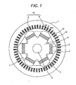
- FIG. 1 is a sectional view of the end of a 6-pole 54-slot permanent magnet type electric rotation machine which is a first embodiment of this invention.
- This machine is better suited for a wind turbine system of a few megawatts (MW) which allows a speed of 1000 to 2000 rpm.
- Stator 1 is of a distributed winding type which distributionally winds coil 10 around stator teeth 12.
- Coil 10 has windings of three phases (U, V, and W) which are disposed so that 6 poles are electrically formed by 54 slots.
- Each stator slot 13 between stator teeth 12 contains upper coil 8 and lower coil 9 as shown in the drawing.
- coil 10 is wound in a so-called distributed winding manner to form 3-phase windings along the periphery.
- Rotor 2 is provided in the center of rotor 1 so as to rotate.
- permanent magnet 3 is provided between rotor core 5 and pole piece 4. Further, rotor core 5 is coupled with shaft 6.
- Pole retainer 7 is provided between two adjoining poles to prevent permanent magnet 3 from moving circumferentially. It is preferable that the pole retainer is made of a non-magnetic material such as aluminum or copper.
- FIG. 2 is a sectional view of the end of a 6-pole 63-slot permanent magnet type electric rotation machine which is a second embodiment of this invention.
- coils 10 are wound distributionally around stator 21 in a so-called distributed winding manner to form 3-phase windings along the periphery.
- Rotor 2 is provided in the center of rotor 1 so as to rotate.
- permanent magnet 3 is provided between rotor core 5 and pole piece 4. Further, rotor core 5 is coupled with shaft 6.
- Pole retainer 7 is provided between two adjoining poles to prevent permanent magnet 3 from moving circumferentially. It is preferable that the pole retainer 7 is made of a non-magnetic material such as aluminum or copper.
- FIG. 3 is a sectional view of the end of a 6-pole 45-slot permanent magnet type electric rotation machine which is a third embodiment of this invention.
- coils 10 are wound distributionally around stator 1 in a so-called distributed winding manner to form 3-phase windings along the periphery.
- Rotor 2 is provided in the center of stator 1 so as to rotate.
- permanent magnet 3 is provided between rotor core 5 and pole piece 4. Further, rotor core 5 is coupled with shaft 6.
- Pole retainer 7 is provided between two adjoining poles to prevent permanent magnet 3 from moving circumferentially. It is preferable that the pole retainer 7 is made of a non-magnetic material such as aluminum or copper.
- FIG. 4 shows the result of analysis of harmonic components in the induced voltage waveform of Embodiment 1.
- the induced voltage waveform contains 17th and 19th harmonic components more with respect to the first harmonic component (100 %) . It is necessary to reduce these harmonic components (except the fundamental wave) to almost 0 to reduce the waveform distortion factor.
- FIG. 5 shows the result of analysis of harmonic components in the induced voltage waveform of Embodiment 2.
- FIG. 6 shows the result of analysis of harmonic components in the induced voltage waveform of Embodiment 3.
- the contents of harmonic components can be reduced by selecting the numbers of slots as shown in Embodiments 2 and 3. Generally, this means that the quotient of the number of slots N 2 per pole per phase Nspp by the product of the number of poles P and the number of phases N is not an integer.
- N s p p N s P ⁇ N
- Nspp is 3.5 as Ns, N, and P are respectively 63, 3, and 6 in that order.
- Nspp is 2.5 as Ns, N, and P are respectively 45, 3, and 6 in that order.
- the waveform distortion factor can be reduced when the Nspp value is not an integer. Specifically, when the Nspp value is 3.5 or 2.5 as shown in Embodiments 2 and 3, the distortion factor can be reduced effectively. Further, the distortion factor of an induced voltage can also be reduced by selecting an adequate width of pole piece of rotor 2 in Embodiment 1.
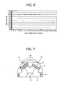
- FIG. 7 is a supplemental drawing to explain Embodiment 1.
- Additional lines 71 and 72 are drawn passing through the center of rotation and the center 73 of the outermost circle of each of the adjoining poles of rotor 2.
- Reference item Tr is an arc between additional lines 71 and 72.
- Pole width rate Pw is expressed by Tr and Tp (the width of each pole piece 4) as shown below.
- P w T p T r ship between pole width rate Pw and induced voltage distortion factor.
- Curved line 81 varies as the pole width rate changes.
- the waveform distortion factor is required to be 10 % or less by the JEC Standards.
- Tp width of pole piece 4 at a pole width rate (Pw) which satisfies Pw ⁇ 0.6, 0.67 ⁇ Pw ⁇ 0.71, or 0.78 ⁇ Pw. From FIG. 8, it is apparent that Tp in the above range can reduce the distortion factor very effectively. As shown in FIG. 9 it is also possible to provide dumper bars 91 on pole piece 4 to make the width (Tp) of pole piece 4 equal to that shown in FIG. 8.
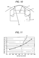
- FIG. 10 is a supplemental drawing to explain a curvature of pole piece 4 of Embodiment 1.
- Rotor 2 has outermost peripheral part 91 of radius R1. It is possible to reduce the induced voltage distortion factor by making radius R2 of the outer periphery of pole piece 4 smaller than R1.
- FIG. 11 shows a relationship between the waveform distortion factor and the quotient of radius R2 of the outer periphery of pole piece 4 by radius R1 of rotor R2.
- Curved line 101 indicates that the waveform distortion factor goes down as the R2/R1 value becomes smaller.
- the R2/R1 value should preferably be about 0.9 or less.
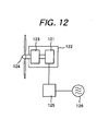
- FIG. 12 shows an example of wind turbine system to which the electric rotation machine of this invention is applied.
- Electric rotation machine 121 of Embodiment 1 to Embodiment 3 is coupled with windmill 124 via speed-up gear 123 and housed in windmill nacelle 122.
- Electric rotation machine 121 is connected to power system 126 via power converter 125 for power generation. It is also possible to connect windmill 122 directly to electric rotation machine 121.
- this example uses winds as its energy source, other energy sources such as water mill, engine, and turbine can be used. Further, this embodiment is applicable to electric motors.
Landscapes
- Engineering & Computer Science (AREA)
- Power Engineering (AREA)
- Manufacturing & Machinery (AREA)
- Permanent Magnet Type Synchronous Machine (AREA)
- Permanent Field Magnets Of Synchronous Machinery (AREA)
- Iron Core Of Rotating Electric Machines (AREA)
- Connection Of Motors, Electrical Generators, Mechanical Devices, And The Like (AREA)
Applications Claiming Priority (1)
| Application Number | Priority Date | Filing Date | Title |
|---|---|---|---|
| JP2005070260A JP4434045B2 (ja) | 2005-03-14 | 2005-03-14 | 回転電機及び風力発電システム |
Publications (3)
| Publication Number | Publication Date |
|---|---|
| EP1703623A2 true EP1703623A2 (fr) | 2006-09-20 |
| EP1703623A3 EP1703623A3 (fr) | 2008-08-27 |
| EP1703623B1 EP1703623B1 (fr) | 2014-12-24 |
Family
ID=36609322
Family Applications (1)
| Application Number | Title | Priority Date | Filing Date |
|---|---|---|---|
| EP06003063.2A Ceased EP1703623B1 (fr) | 2005-03-14 | 2006-02-15 | Machine éléctrique rotative et systeme d'eolienne |
Country Status (5)
| Country | Link |
|---|---|
| US (2) | US7498707B2 (fr) |
| EP (1) | EP1703623B1 (fr) |
| JP (1) | JP4434045B2 (fr) |
| KR (1) | KR20060100926A (fr) |
| CN (1) | CN1835350A (fr) |
Cited By (2)
| Publication number | Priority date | Publication date | Assignee | Title |
|---|---|---|---|---|
| DE102007011261A1 (de) * | 2007-03-06 | 2008-09-11 | Vensys Energy Ag | Generator für Windenergieanlagen |
| US8344569B2 (en) | 2009-05-14 | 2013-01-01 | Vensys Energy Ag | Generator for wind power installations |
Families Citing this family (19)
| Publication number | Priority date | Publication date | Assignee | Title |
|---|---|---|---|---|
| US7939958B2 (en) * | 2007-06-01 | 2011-05-10 | Bill Todorof | Direct drive wind turbine and blade assembly |
| US8072108B2 (en) * | 2009-10-30 | 2011-12-06 | Finkle Louis J | Electric motor or generator with mechanically tuneable permanent magnetic field |
| US8288908B2 (en) * | 2009-10-30 | 2012-10-16 | Finkle Louis J | Reconfigurable inductive to synchronous motor |
| US8952587B2 (en) | 2009-10-30 | 2015-02-10 | Louis J. Finkle | Windmill generator with mechanically tuneable permanent magnetic field |
| DE102010029514A1 (de) * | 2010-05-31 | 2011-12-01 | Robert Bosch Gmbh | Elektrische Maschine mit reduzierter Geräuschentwicklung |
| US8632251B2 (en) | 2010-06-24 | 2014-01-21 | Schaeffler Technologies AG & Co. KG | Bearing closure/shield for current passage in electric equipment |
| JP4725684B1 (ja) | 2010-08-10 | 2011-07-13 | 株式会社安川電機 | 発電機および風力発電システム |
| US8749103B2 (en) * | 2010-09-15 | 2014-06-10 | Remy Technologies, L.L.C. | Permanent magnet rotor for electric machine |
| US9172279B2 (en) * | 2011-02-04 | 2015-10-27 | Mitsubishi Electric Corporation | Automotive embedded permanent magnet rotary electric machine |
| JP5261539B2 (ja) * | 2011-06-13 | 2013-08-14 | トヨタ自動車株式会社 | 電磁石型回転電機 |
| JP2013013250A (ja) * | 2011-06-29 | 2013-01-17 | Mitsuba Corp | 3相誘導電動機 |
| ES2718096T3 (es) | 2011-11-30 | 2019-06-27 | Abb Research Ltd | Maquinas eléctricas y rotores de máquinas eléctricas |
| US9484794B2 (en) | 2012-04-20 | 2016-11-01 | Louis J. Finkle | Hybrid induction motor with self aligning permanent magnet inner rotor |
| US9419504B2 (en) | 2012-04-20 | 2016-08-16 | Louis J. Finkle | Hybrid induction motor with self aligning permanent magnet inner rotor |
| US8992091B2 (en) | 2012-05-11 | 2015-03-31 | Schaeffler Technologies AG & Co. KG | Closure design of a conductive rubber material for allowing current passage through a bearing in electric machines |
| US10998802B2 (en) | 2017-02-21 | 2021-05-04 | Louis J. Finkle | Hybrid induction motor with self aligning hybrid induction/permanent magnet rotor |
| US9923439B2 (en) | 2014-01-09 | 2018-03-20 | Motor Generator Technology, Inc. | Hybrid electric motor with self aligning permanent magnet and squirrel cage rotors |
| US10476363B2 (en) | 2014-01-09 | 2019-11-12 | Louis J. Finkle | Hybrid electric motor with self aligning permanent magnet and squirrel cage dual rotors magnetically coupled with permeant magnets and bars at synchronous speed |
| US9923440B2 (en) | 2014-01-09 | 2018-03-20 | Motor Generator Technology, Inc. | Hybrid electric motor with self aligning permanent magnet and squirrel cage rotors |
Citations (2)
| Publication number | Priority date | Publication date | Assignee | Title |
|---|---|---|---|---|
| JP2001069735A (ja) | 1999-08-31 | 2001-03-16 | Toshiba Corp | 永久磁石式リラクタンス型回転電機 |
| DE202004016534U1 (de) | 2003-11-05 | 2005-01-05 | Ebm-Papst St. Georgen Gmbh & Co. Kg | Elektromotor |
Family Cites Families (14)
| Publication number | Priority date | Publication date | Assignee | Title |
|---|---|---|---|---|
| US4190779A (en) * | 1976-05-04 | 1980-02-26 | Ernest Schaeffer | Step motors |
| DE69323314T2 (de) * | 1992-08-12 | 1999-06-17 | Seiko Epson Corp., Tokio/Tokyo | Steuerverfahren eines bürstenlosen gleichstrommotor |
| JP3308828B2 (ja) * | 1996-10-18 | 2002-07-29 | 株式会社日立製作所 | 永久磁石回転電機及びそれを用いた電動車両 |
| US6087751A (en) * | 1997-07-01 | 2000-07-11 | Kabushiki Kaisha Toshiba | Reluctance type rotating machine with permanent magnets |
| US6274960B1 (en) * | 1998-09-29 | 2001-08-14 | Kabushiki Kaisha Toshiba | Reluctance type rotating machine with permanent magnets |
| US6127739A (en) * | 1999-03-22 | 2000-10-03 | Appa; Kari | Jet assisted counter rotating wind turbine |
| JP2000350393A (ja) * | 1999-03-29 | 2000-12-15 | Shin Etsu Chem Co Ltd | 永久磁石モータ |
| JP3513467B2 (ja) * | 2000-06-16 | 2004-03-31 | ファナック株式会社 | 同期電動機のロータ |
| JP2002101628A (ja) * | 2000-09-22 | 2002-04-05 | Hitachi Ltd | 永久磁石式回転電機 |
| US6856051B2 (en) * | 2001-10-03 | 2005-02-15 | Delphi Technologies, Inc. | Manufacturing method and composite powder metal rotor assembly for circumferential type interior permanent magnet machine |
| US7230359B2 (en) * | 2002-03-22 | 2007-06-12 | Ebm-Papst St. Georgen Gmbh & Co. Kg | Electric motor with poles shaped to minimize cogging torque |
| DE10394041T5 (de) * | 2003-01-15 | 2005-12-22 | Mitsubishi Denki K.K. | Permanentmagnetmotor |
| US7042127B2 (en) * | 2003-04-02 | 2006-05-09 | Nidec Sankyo Corporation | Permanent magnet embedded motor |
| JP2005006425A (ja) * | 2003-06-12 | 2005-01-06 | Neomax Co Ltd | 風力発電機とその設計方法 |
-
2005
- 2005-03-14 JP JP2005070260A patent/JP4434045B2/ja not_active Expired - Fee Related
- 2005-12-19 CN CNA2005101191878A patent/CN1835350A/zh active Pending
-
2006
- 2006-02-15 EP EP06003063.2A patent/EP1703623B1/fr not_active Ceased
- 2006-02-17 KR KR1020060015682A patent/KR20060100926A/ko not_active Ceased
- 2006-02-17 US US11/356,111 patent/US7498707B2/en not_active Expired - Lifetime
-
2009
- 2009-02-18 US US12/388,189 patent/US7737593B2/en not_active Expired - Fee Related
Patent Citations (2)
| Publication number | Priority date | Publication date | Assignee | Title |
|---|---|---|---|---|
| JP2001069735A (ja) | 1999-08-31 | 2001-03-16 | Toshiba Corp | 永久磁石式リラクタンス型回転電機 |
| DE202004016534U1 (de) | 2003-11-05 | 2005-01-05 | Ebm-Papst St. Georgen Gmbh & Co. Kg | Elektromotor |
Cited By (2)
| Publication number | Priority date | Publication date | Assignee | Title |
|---|---|---|---|---|
| DE102007011261A1 (de) * | 2007-03-06 | 2008-09-11 | Vensys Energy Ag | Generator für Windenergieanlagen |
| US8344569B2 (en) | 2009-05-14 | 2013-01-01 | Vensys Energy Ag | Generator for wind power installations |
Also Published As
| Publication number | Publication date |
|---|---|
| EP1703623A3 (fr) | 2008-08-27 |
| EP1703623B1 (fr) | 2014-12-24 |
| JP4434045B2 (ja) | 2010-03-17 |
| US20090160284A1 (en) | 2009-06-25 |
| US7498707B2 (en) | 2009-03-03 |
| JP2006254638A (ja) | 2006-09-21 |
| KR20060100926A (ko) | 2006-09-21 |
| US20060202581A1 (en) | 2006-09-14 |
| CN1835350A (zh) | 2006-09-20 |
| US7737593B2 (en) | 2010-06-15 |
Similar Documents
| Publication | Publication Date | Title |
|---|---|---|
| US7737593B2 (en) | Electrical rotation machine and a wind turbine system | |
| JP4311643B2 (ja) | 永久磁石型回転電機の製造方法および風力発電用永久磁石型同期発電機の製造方法 | |
| EP2149964B1 (fr) | Générateur synchrone et système de générateur synchrone | |
| US8928199B2 (en) | Wound rotor brushless doubly-fed motor | |
| JP5060546B2 (ja) | 永久磁石式発電機とそれを用いた風力発電機 | |
| EP2421123A2 (fr) | Générateur d'énergie | |
| Liu et al. | A family of vernier permanent magnet machines utilizing an alternating rotor leakage flux blocking design | |
| US6943462B2 (en) | Ring generator for a wind power installation | |
| Pakdelian et al. | An electric machine integrated with trans-rotary magnetic gear | |
| Zohoori et al. | Design study of FSPM generator with novel outer rotor configuration for small wind turbine application | |
| Borkowski et al. | Universal modular permanent magnet synchronous generator for small low-head hydropower plants | |
| US20040090136A1 (en) | Three-phase alternating current generator | |
| JP5594660B2 (ja) | リラクタンス発電機 | |
| Kouhshahi et al. | An axial flux-focusing magnetically geared motor | |
| Ye et al. | 10 MW direct-drive superconducting vernier machines for offshore wind power application | |
| Chu et al. | Performance of series hybrid excitation synchronous machine in comparison with wound field synchronous machine | |
| Dobzhanskyi | Comparison analysis of cylindrical and rectangular linear permanent magnet transverse-flux machines for wave energy applications | |
| McDonald et al. | Design of generators for offshore wind turbines | |
| KR101905512B1 (ko) | 기동 장치가 필요 없는 영구자석 단상 모터 | |
| Abolhassani | A new concentrated windings surface mounted permanent magnet synchronous machine for wind energy application | |
| Jadoon et al. | Design optimization and generating characteristics of a linear arc PM vernier machine for wave energy conversion system | |
| Kim et al. | Torque Harmonics Mitigation in Wound Field Synchronous Generators With Asymmetric Rotors for More Electric Aircraft | |
| Keppola et al. | Preliminary test results of an axial flux toroidal stator wind power generator | |
| Awah | Novel double stator switched flux permanent magnet machines | |
| Chen et al. | Cost reduction of vernier permanent-magnet machine with ferrite magnets |
Legal Events
| Date | Code | Title | Description |
|---|---|---|---|
| PUAI | Public reference made under article 153(3) epc to a published international application that has entered the european phase |
Free format text: ORIGINAL CODE: 0009012 |
|
| AK | Designated contracting states |
Kind code of ref document: A2 Designated state(s): AT BE BG CH CY CZ DE DK EE ES FI FR GB GR HU IE IS IT LI LT LU LV MC NL PL PT RO SE SI SK TR |
|
| AX | Request for extension of the european patent |
Extension state: AL BA HR MK YU |
|
| 17P | Request for examination filed |
Effective date: 20080331 |
|
| PUAL | Search report despatched |
Free format text: ORIGINAL CODE: 0009013 |
|
| AK | Designated contracting states |
Kind code of ref document: A3 Designated state(s): AT BE BG CH CY CZ DE DK EE ES FI FR GB GR HU IE IS IT LI LT LU LV MC NL PL PT RO SE SI SK TR |
|
| AX | Request for extension of the european patent |
Extension state: AL BA HR MK YU |
|
| 17Q | First examination report despatched |
Effective date: 20090401 |
|
| AKX | Designation fees paid |
Designated state(s): DE FI |
|
| GRAP | Despatch of communication of intention to grant a patent |
Free format text: ORIGINAL CODE: EPIDOSNIGR1 |
|
| INTG | Intention to grant announced |
Effective date: 20140704 |
|
| GRAS | Grant fee paid |
Free format text: ORIGINAL CODE: EPIDOSNIGR3 |
|
| GRAA | (expected) grant |
Free format text: ORIGINAL CODE: 0009210 |
|
| AK | Designated contracting states |
Kind code of ref document: B1 Designated state(s): DE FI |
|
| REG | Reference to a national code |
Ref country code: DE Ref legal event code: R096 Ref document number: 602006044068 Country of ref document: DE Effective date: 20150226 |
|
| REG | Reference to a national code |
Ref country code: DE Ref legal event code: R097 Ref document number: 602006044068 Country of ref document: DE |
|
| PLBE | No opposition filed within time limit |
Free format text: ORIGINAL CODE: 0009261 |
|
| STAA | Information on the status of an ep patent application or granted ep patent |
Free format text: STATUS: NO OPPOSITION FILED WITHIN TIME LIMIT |
|
| 26N | No opposition filed |
Effective date: 20150925 |
|
| PGFP | Annual fee paid to national office [announced via postgrant information from national office to epo] |
Ref country code: FI Payment date: 20210209 Year of fee payment: 16 |
|
| PGFP | Annual fee paid to national office [announced via postgrant information from national office to epo] |
Ref country code: DE Payment date: 20210202 Year of fee payment: 16 |
|
| REG | Reference to a national code |
Ref country code: DE Ref legal event code: R119 Ref document number: 602006044068 Country of ref document: DE |
|
| REG | Reference to a national code |
Ref country code: FI Ref legal event code: MAE |
|
| PG25 | Lapsed in a contracting state [announced via postgrant information from national office to epo] |
Ref country code: FI Free format text: LAPSE BECAUSE OF NON-PAYMENT OF DUE FEES Effective date: 20220215 |
|
| PG25 | Lapsed in a contracting state [announced via postgrant information from national office to epo] |
Ref country code: DE Free format text: LAPSE BECAUSE OF NON-PAYMENT OF DUE FEES Effective date: 20220901 |