EP1703945B1 - Procede et appareil pour la prediction d'arythmies utilisant la frequence cardiaque diurne - Google Patents
Procede et appareil pour la prediction d'arythmies utilisant la frequence cardiaque diurne Download PDFInfo
- Publication number
- EP1703945B1 EP1703945B1 EP04812942A EP04812942A EP1703945B1 EP 1703945 B1 EP1703945 B1 EP 1703945B1 EP 04812942 A EP04812942 A EP 04812942A EP 04812942 A EP04812942 A EP 04812942A EP 1703945 B1 EP1703945 B1 EP 1703945B1
- Authority
- EP
- European Patent Office
- Prior art keywords
- heart rate
- day
- patient
- night
- arrhythmia
- Prior art date
- Legal status (The legal status is an assumption and is not a legal conclusion. Google has not performed a legal analysis and makes no representation as to the accuracy of the status listed.)
- Expired - Lifetime
Links
Images

Classifications
-
- A—HUMAN NECESSITIES
- A61—MEDICAL OR VETERINARY SCIENCE; HYGIENE
- A61B—DIAGNOSIS; SURGERY; IDENTIFICATION
- A61B5/00—Measuring for diagnostic purposes; Identification of persons
- A61B5/72—Signal processing specially adapted for physiological signals or for diagnostic purposes
- A61B5/7271—Specific aspects of physiological measurement analysis
- A61B5/7275—Determining trends in physiological measurement data; Predicting development of a medical condition based on physiological measurements, e.g. determining a risk factor
-
- A—HUMAN NECESSITIES
- A61—MEDICAL OR VETERINARY SCIENCE; HYGIENE
- A61B—DIAGNOSIS; SURGERY; IDENTIFICATION
- A61B5/00—Measuring for diagnostic purposes; Identification of persons
- A61B5/02—Detecting, measuring or recording for evaluating the cardiovascular system, e.g. pulse, heart rate, blood pressure or blood flow
- A61B5/024—Measuring pulse rate or heart rate
- A61B5/02405—Determining heart rate variability
-
- A—HUMAN NECESSITIES
- A61—MEDICAL OR VETERINARY SCIENCE; HYGIENE
- A61B—DIAGNOSIS; SURGERY; IDENTIFICATION
- A61B5/00—Measuring for diagnostic purposes; Identification of persons
- A61B5/02—Detecting, measuring or recording for evaluating the cardiovascular system, e.g. pulse, heart rate, blood pressure or blood flow
- A61B5/024—Measuring pulse rate or heart rate
- A61B5/02438—Measuring pulse rate or heart rate with portable devices, e.g. worn by the patient
-
- A—HUMAN NECESSITIES
- A61—MEDICAL OR VETERINARY SCIENCE; HYGIENE
- A61B—DIAGNOSIS; SURGERY; IDENTIFICATION
- A61B5/00—Measuring for diagnostic purposes; Identification of persons
- A61B5/02—Detecting, measuring or recording for evaluating the cardiovascular system, e.g. pulse, heart rate, blood pressure or blood flow
- A61B5/024—Measuring pulse rate or heart rate
- A61B5/0245—Measuring pulse rate or heart rate by using sensing means generating electric signals, i.e. ECG signals
- A61B5/02455—Measuring pulse rate or heart rate by using sensing means generating electric signals, i.e. ECG signals provided with high/low alarm devices
-
- A—HUMAN NECESSITIES
- A61—MEDICAL OR VETERINARY SCIENCE; HYGIENE
- A61B—DIAGNOSIS; SURGERY; IDENTIFICATION
- A61B5/00—Measuring for diagnostic purposes; Identification of persons
- A61B5/24—Detecting, measuring or recording bioelectric or biomagnetic signals of the body or parts thereof
- A61B5/316—Modalities, i.e. specific diagnostic methods
- A61B5/318—Heart-related electrical modalities, e.g. electrocardiography [ECG]
- A61B5/346—Analysis of electrocardiograms
- A61B5/349—Detecting specific parameters of the electrocardiograph cycle
- A61B5/363—Detecting tachycardia or bradycardia
-
- A—HUMAN NECESSITIES
- A61—MEDICAL OR VETERINARY SCIENCE; HYGIENE
- A61N—ELECTROTHERAPY; MAGNETOTHERAPY; RADIATION THERAPY; ULTRASOUND THERAPY
- A61N1/00—Electrotherapy; Circuits therefor
- A61N1/18—Applying electric currents by contact electrodes
- A61N1/32—Applying electric currents by contact electrodes alternating or intermittent currents
- A61N1/36—Applying electric currents by contact electrodes alternating or intermittent currents for stimulation
- A61N1/362—Heart stimulators
- A61N1/365—Heart stimulators controlled by a physiological parameter, e.g. heart potential
-
- G—PHYSICS
- G16—INFORMATION AND COMMUNICATION TECHNOLOGY [ICT] SPECIALLY ADAPTED FOR SPECIFIC APPLICATION FIELDS
- G16H—HEALTHCARE INFORMATICS, i.e. INFORMATION AND COMMUNICATION TECHNOLOGY [ICT] SPECIALLY ADAPTED FOR THE HANDLING OR PROCESSING OF MEDICAL OR HEALTHCARE DATA
- G16H20/00—ICT specially adapted for therapies or health-improving plans, e.g. for handling prescriptions, for steering therapy or for monitoring patient compliance
- G16H20/30—ICT specially adapted for therapies or health-improving plans, e.g. for handling prescriptions, for steering therapy or for monitoring patient compliance relating to physical therapies or activities, e.g. physiotherapy, acupressure or exercising
-
- G—PHYSICS
- G16—INFORMATION AND COMMUNICATION TECHNOLOGY [ICT] SPECIALLY ADAPTED FOR SPECIFIC APPLICATION FIELDS
- G16H—HEALTHCARE INFORMATICS, i.e. INFORMATION AND COMMUNICATION TECHNOLOGY [ICT] SPECIALLY ADAPTED FOR THE HANDLING OR PROCESSING OF MEDICAL OR HEALTHCARE DATA
- G16H50/00—ICT specially adapted for medical diagnosis, medical simulation or medical data mining; ICT specially adapted for detecting, monitoring or modelling epidemics or pandemics
- G16H50/20—ICT specially adapted for medical diagnosis, medical simulation or medical data mining; ICT specially adapted for detecting, monitoring or modelling epidemics or pandemics for computer-aided diagnosis, e.g. based on medical expert systems
-
- G—PHYSICS
- G16—INFORMATION AND COMMUNICATION TECHNOLOGY [ICT] SPECIALLY ADAPTED FOR SPECIFIC APPLICATION FIELDS
- G16H—HEALTHCARE INFORMATICS, i.e. INFORMATION AND COMMUNICATION TECHNOLOGY [ICT] SPECIALLY ADAPTED FOR THE HANDLING OR PROCESSING OF MEDICAL OR HEALTHCARE DATA
- G16H50/00—ICT specially adapted for medical diagnosis, medical simulation or medical data mining; ICT specially adapted for detecting, monitoring or modelling epidemics or pandemics
- G16H50/30—ICT specially adapted for medical diagnosis, medical simulation or medical data mining; ICT specially adapted for detecting, monitoring or modelling epidemics or pandemics for calculating health indices; for individual health risk assessment
-
- A—HUMAN NECESSITIES
- A61—MEDICAL OR VETERINARY SCIENCE; HYGIENE
- A61B—DIAGNOSIS; SURGERY; IDENTIFICATION
- A61B5/00—Measuring for diagnostic purposes; Identification of persons
- A61B5/0002—Remote monitoring of patients using telemetry, e.g. transmission of vital signals via a communication network
- A61B5/0031—Implanted circuitry
-
- A—HUMAN NECESSITIES
- A61—MEDICAL OR VETERINARY SCIENCE; HYGIENE
- A61B—DIAGNOSIS; SURGERY; IDENTIFICATION
- A61B5/00—Measuring for diagnostic purposes; Identification of persons
- A61B5/02—Detecting, measuring or recording for evaluating the cardiovascular system, e.g. pulse, heart rate, blood pressure or blood flow
- A61B5/021—Measuring pressure in heart or blood vessels
- A61B5/0215—Measuring pressure in heart or blood vessels by means inserted into the body
-
- A—HUMAN NECESSITIES
- A61—MEDICAL OR VETERINARY SCIENCE; HYGIENE
- A61N—ELECTROTHERAPY; MAGNETOTHERAPY; RADIATION THERAPY; ULTRASOUND THERAPY
- A61N1/00—Electrotherapy; Circuits therefor
- A61N1/18—Applying electric currents by contact electrodes
- A61N1/32—Applying electric currents by contact electrodes alternating or intermittent currents
- A61N1/36—Applying electric currents by contact electrodes alternating or intermittent currents for stimulation
- A61N1/362—Heart stimulators
- A61N1/3621—Heart stimulators for treating or preventing abnormally high heart rate
- A61N1/3622—Heart stimulators for treating or preventing abnormally high heart rate comprising two or more electrodes co-operating with different heart regions
Definitions
- the present invention relates to implantable medical devices and, more particularly, to apparatus for predicting arrhythmias to enable deployment of targeted interventions for prevention prior to the occurrence of the predicted arrhythmia.
- Implantable medical devices referred to as implantable cardioverter defibrillators or ICDs, are capable of automatically detecting arrhythmias, such as ventricular tachycardia (VT) and ventricular fibrillation (VF), and delivering anti-arrhythmia therapies. Delivering anti-tachycardia pacing therapies or high-energy shock therapies may terminate VT and VF.
- Ventricular tachycardia termination is typically referred to as “cardioversion.”
- Ventricular fibrillation termination is typically referred to as "defibrillation.”
- a number of parameters for predicting a discreet VT or VF episode have been proposed including, for example, left ventricular dysfunction, myocardial ischemia, frequency of ventricular ectopic beats, heart rate variability, heart rate turbulence, or other electrocardiographic changes (see Shusterman et al., J Am Coll Cardiol. 1998;32:1891-9 , and Schmidt et al., Lancet. 1999;353:1390-96 ). Changes in the autonomic nervous system are known contributing factors to arrhythmogenesis.
- the heart rate is normally regulated by a balance between the sympathetic and parasympathetic (vagal) components of the autonomic nervous system. Increased sympathetic activity, referred to as sympathetic tone, increases the heart rate and decreases heart rate variability.
- Heart rate variability is the variation in consecutive heart rate cycles, which may be measured as ventricular cycle intervals, known as "R-R intervals,” or as atrial cycle intervals, known as "A-A intervals.”
- RV Heart rate variability
- A-A intervals Atrial cycle intervals
- VT/VF episodes Some patients experience recurring VT or VF episodes. Based on the ICD database, a majority of VT/VF episodes occur in forms of "electrical storms" or "clustering" that is defined as a rate of 3 or more VT/VF episodes within a 24-hour period (see Groenefeld et al., European Heart Journal. 2000;21 (suppl):199 , and Zhou et al., J. Am. Coll. Cardiol. 2002;39(suppl. A):86A-87A ). Patients who experience electrical storms are at greater risk for subsequent death than patients who experience discreet episodes of VT or VF. Electrical storms are estimated to occur in approximately 10 to 30% of patients having ICDs. (See Bansch et al., J. Am. Coll. Cardiol., 2000;36:566-73 , and Exner et al., Circulation., 2001; 103:2066-2071 .
- the present invention also provides apparatus as defined in the independent claim(s)).
- the present invention is directed to predicting arrhythmia, such as ventricular tachycardia, for example, using a quantitive measure in order to allow assessment of patient risk and to enable preventative interventions by the device and clinicians.
- arrhythmia such as ventricular tachycardia
- the trending of day and night average heart rates, along with patient physical activity can be analyzed to provide prediction of impending arrhythmia within weeks.
- day and night average heart rate for crossover points, where the night heart rate equals or exceeds the day rate, and monitoring for a concomitant elevation in the night heart rate from a reference value, specific days heralding an increased risk of arrhythmia can be determined.
- the present invention may be incorporated in an implantable or external monitoring device, or an implantable or external cardiac rhythm management device.
- the present invention is incorporated in an implantable cardiac device capable of monitoring the heart rhythm for detecting arrhythmias and delivering anti-arrhythmia therapies, such as the implantable cardioverter defibrillator (ICD) 10 shown in FIG. 1 .
- ICD implantable cardioverter defibrillator
- ICD 10 is shown coupled to a patient's heart by way of three leads 6, 15, and 16.
- a connector block 12 receives the proximal end of a right ventricular lead 16, a right atrial lead 15 and a coronary sinus lead 6, used for positioning electrodes for sensing and stimulation in three or four heart chambers.
- the right ventricular lead 16 is positioned such that its distal end is in the right ventricle for sensing right ventricular cardiac signals and delivering pacing or shocking pulses in the right ventricle.
- right ventricular lead 16 is equipped with a ring electrode 24, an extendable helix electrode 26 mounted retractably within an electrode head 28, and a coil electrode 20, each of which are connected to an insulated conductor within the body of lead 16.
- the proximal end of the insulated conductors are coupled to corresponding connectors carried by bifurcated connector 14 at the proximal end of lead 16 for providing electrical connection to the ICD 10.
- the right atrial lead 15 is positioned such that its distal end is in the vicinity of the right atrium and the superior vena cava.
- Lead 15 is equipped with a ring electrode 21 and an extendable helix electrode 17, mounted retractably within electrode head 19, for sensing and pacing in the right atrium.
- Lead 15 is further equipped with a coil electrode 23 for delivering high-energy shock therapy.
- the ring electrode 21, the helix electrode 17 and the coil electrode 23 are each connected to an insulated conductor with the body of the right atrial lead 15. Each insulated conductor is coupled at its proximal end to a connector carried by bifurcated connector 13.
- the coronary sinus lead 6 is advanced within the vasculature of the left side of the heart via the coronary sinus and great cardiac vein.
- the coronary sinus lead 6 is shown in the embodiment of FIG. 1 as having a defibrillation coil electrode 8 that may be used in combination with either the coil electrode 20 or the coil electrode 23 for delivering electrical shocks for cardioversion and defibrillation therapies.
- coronary sinus lead 6 may also be equipped with a distal tip electrode and ring electrode for pacing and sensing functions in the left chambers of the heart.
- the coil electrode 8 is coupled to an insulated conductor within the body of lead 6, which provides connection to the proximal connector 4.
- the electrodes 17 and 21 or 24 and 26 may be used as bipolar pairs, commonly referred to as a "tip-to-ring” configuration, or individually in a unipolar configuration with the device housing 11 serving as the indifferent electrode, commonly referred to as the "can" or “case” electrode.
- the device housing 11 may also serve as a subcutaneous defibrillation electrode in combination with one or more of the coil electrodes 8, 20 or 23 for defibrillation of the atria or ventricles. It is recognized that alternate lead systems may be substituted for the three lead system illustrated in FIG. 1 .
- ventricular tachycardia or fibrillation can be determined by sensing only signals derived from the right ventricle
- a multi-chamber system is illustrated so as to indicate the scope of the invention. It is understood that the invention may normally be practiced with a multi-chamber, dual chamber, or single chamber device.
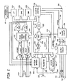
- FIG. 2 A functional schematic diagram of the ICD 10 is shown in FIG. 2 .
- This diagram should be taken as exemplary of the type of device in which the invention may be embodied and not as limiting.
- the disclosed embodiment shown in FIG. 2 is a microprocessor-controlled device, but the methods of the present invention may also be practiced in other types of devices such as those employing dedicated digital circuitry.
- the ICD 10 is provided with a number of connection terminals for achieving electrical connection to the leads 6, 15, and 16 and their respective electrodes.
- the connection terminal 311 provides electrical connection to the housing 11 for use as the indifferent electrode during unipolar stimulation or sensing.
- the connection terminals 320, 310, and 318 provide electrical connection to coil electrodes 20, 8 and 28 respectively.
- Each of these connection terminals 311, 320, 310, and 318 are coupled to the high voltage output circuit 234 to facilitate the delivery of high energy shocking pulses to the heart using one or more of the coil electrodes 8, 20, and 28 and optionally the housing 11.
- connection terminals 317 and 321 provide electrical connection to the helix electrode 17 and the ring electrode 21 positioned in the right atrium.
- the connection terminals 317 and 321 are further coupled to an atrial sense amplifier 204 for sensing atrial signals such as P-waves.
- the connection terminals 326 and 324 provide electrical connection to the helix electrode 26 and the ring electrode 24 positioned in the right ventricle.
- the connection terminals 326 and 324 are further coupled to a ventricular sense amplifier 200 for sensing ventricular signals.
- the atrial sense amplifier 204 and the ventricular sense amplifier 200 preferably take the form of automatic gain controlled amplifiers with adjustable sensing thresholds.
- the general operation of the ventricular sense amplifier 200 and the atrial sense amplifier 204 may correspond to that disclosed in U.S. Pat. No. 5,117,824, by Keimel, et al. .
- Atrial sense amplifier 204 Whenever a signal received by atrial sense amplifier 204 exceeds an atrial sensing threshold, a signal is generated on the P-out signal line 206. Whenever a signal received by the ventricular sense amplifier 200 exceeds a ventricular sensing threshold, a signal is generated on the R-out signal line 202.
- Switch matrix 208 is used to select which of the available electrodes are coupled to a wide band amplifier 210 for use in digital signal analysis. Selection of the electrodes is controlled by the microprocessor 224 via data/address bus 218. The selected electrode configuration may be varied as desired for the various sensing, pacing, cardioversion and defibrillation functions of the ICD 10. Signals from the electrodes selected for coupling to bandpass amplifier 210 are provided to multiplexer 220, and thereafter converted to multibit digital signals by A/D converter 222, for storage in random access memory 226 under control of direct memory access circuit 228.
- Microprocessor 224 may employ digital signal analysis techniques to characterize the digitized signals stored in random access memory 226 to recognize and classify the patient's heart rhythm employing any of the numerous signal processing methodologies known in the art.
- a tachyarrhythmia recognition mechanism is described in the previously referenced U.S. Pat. No. 5,545,186 issued to Olson et al.
- the telemetry circuit 330 receives downlink telemetry from and sends uplink telemetry to an external programmer, as is conventional in implantable anti-arrhythmia devices, by means of an antenna 332. Data to be uplinked to the programmer and control signals for the telemetry circuit are provided by microprocessor 224 via address/data bus 218.
- Received telemetry is provided to microprocessor 224 via multiplexer 220. Numerous types of telemetry systems known for use in implantable devices may be used.
- the telemetry circuit 330 is also used for communication with a patient activator in one embodiment of the present invention.
- the device 10 is equipped with a sensor 344 and sensor processing circuitry 342.
- the sensor 344 may be located within the device housing 10 or external to the device housing 10 but implanted within the body of the patient.
- the sensor 344 is used for determining the patient's activity level.
- the sensor 344 may take the form of a piezoelectric crystal as generally described in U.S. Pat. No. 4,428,378 issued to Anderson et al.
- the sensor 344 may also represent a pressure sensor for sensing a patient's blood pressure within the heart chambers or vasculature.
- a change in blood pressure can trigger an autonomic response, and therefore, in one embodiment of the present invention, monitoring a patient's blood pressure may be advantageous in assessing autonomic tone and predicting an electrical storm.
- Pressure sensors that may be implemented with the ICD 10 are generally described in U.S. Pat. No. 6,171,252 to Roberts , and U.S. Pat. No. 6,221,024 to Miesel .
- the pacer timing and control circuitry 212 includes programmable digital counters which control the basic time intervals associated with various single, dual or multi-chamber pacing modes or anti-tachycardia pacing therapies delivered in the atria or ventricles. Pacer circuitry 212 also determines the amplitude of the cardiac pacing pulses under the control of microprocessor 224.
- escape interval counters within pacer timing and control circuitry 212 are reset upon sensing of R-waves or P-waves as indicated by signals on lines 202 and 206, respectively.
- pacing pulses are generated by atrial pacer output circuit 214 and ventricular pacer output circuit 216.
- the pacer output circuits 214 and 216 are coupled to the desired electrodes for pacing via switch matrix 208.
- the escape interval counters are reset upon generation of pacing pulses, and thereby control the basic timing of cardiac pacing functions, including anti-tachycardia pacing.
- the durations of the escape intervals are determined by microprocessor 224 via data/address bus 218.
- the value of the count present in the escape interval counters when reset by sensed R-waves or P-waves can be used to measure R-R intervals and P-P intervals for detecting the occurrence of a variety of arrhythmias.
- the microprocessor 224 includes associated ROM in which stored programs controlling the operation of the microprocessor 224 reside.
- a portion of the memory 226 may be configured as a number of re-circulating buffers capable of holding a series of measured intervals for analysis by the microprocessor 224 for predicting or diagnosing an arrhythmia.
- anti-tachycardia pacing therapy can be delivered by loading a regimen from microcontroller 224 into the pacer timing and control circuitry 212 according to the type of tachycardia detected.
- microprocessor 224 activates the cardioversion and defibrillation control circuitry 230 to initiate charging of the high voltage capacitors 246 and 248 via charging circuit 236 under the control of high voltage charging control line 240.
- the voltage on the high voltage capacitors is monitored via a voltage capacitor (VCAP) line 244, which is passed through the multiplexer 220.
- VCAP voltage capacitor
- the defibrillation or cardioversion pulse is delivered to the heart under the control of the pacer timing and control circuitry 212 by an output circuit 234 via a control bus 238.
- the output circuit 234 determines the electrodes used for delivering the cardioversion or defibrillation pulse and the pulse wave shape.
- the ICD 10 may be equipped with a patient notification system 150 used to notify the patient that a recurring VT or VF episode is predicted. Any known patient notification method may be used such as generating a perceivable twitch stimulation or an audible sound under the control of microprocessor 224.
- a patient notification system may include an audio transducer that emits audible sounds including voiced statements or musical tones stored in analog memory and correlated to a programming or interrogation operating algorithm or to a warning trigger event as generally described in U.S. Pat. No. 6,067,473 issued to Greeninger et al.
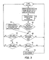
- Fig. 3 is a flow chart illustrating a method performed by a medical device for predicting an arrhythmia according to the present invention.
- the present invention is embodied in a medical device that monitors the heart rate of the patient on serial days, along with the physical activity of the patient via a means that produces relative measures of activity as known in the art, such as an accelerometer, for example.
- the day is divided up into a night period and a day period, the rates for each period are determined by averaging all the cardiac intervals occurring during the period.
- the night period is chosen to reflect the most likely time for the patient to be asleep (here specifically midnight to 04:00).
- the day period is meant to cover the range of time in which the patient is expected to engage in physical activity (here 08:00 to 20:00). If atrial fibrillation or flutter occurs during the day, it is not used and no prediction attempt is made for the day and the day is not used as a reference toward future days.
- Each day the day heart rate and the night heart rate are compared to each other. If the night heart rate meets or exceeds the day heart rate, and the day and night heart rate exceed reference values based on the patient history of rates, then the day's information is considered a prediction or tachyarrhythmic activity within the next day to two weeks.
- the determination of the reference values for day and night heart rate is related to patient activity.
- the most recent three week period for which the maximum 7-day averaged activity measure is no more than 20% greater than the minimum 7-day averaged activity measure is used to compute the references.
- the day heart rate reference is the average of the average day heart rates in the period.
- the night heart rate reference is the average of the night heart rates in the period.
- the heart rate references should be no older than 12 months from the current day, and may occur more often.
- An absolute lower bound on the number of averages in the reference period and a lower bound on the average activity levels may also be applied in determining a valid reference period.
- an average night heart rate (NHR) and an average day heart rate (DHR), along with an activity level are calculated each day, Block 400.
- NHR average night heart rate
- DHR average day heart rate
- Block 400 a running average for activity level is determined over a predetermined period of time, Block 402, such as seven days for example, a determination is made both as to whether the patient has experienced stable cardiac activity over a predetermined period of time, such as 21 days, for example, and whether the running average for activity level is greater than a predetermined minimum activity threshold, Block 404.
- Block 404 a reference value for the day heart rate Dref and a reference value for the night heart rate Nref are calculated and stored, Block 406.
- the process waits for the rate and activity levels for the next day. If both the night heart rate reference Nref and day heart rate reference Dref have been calculated and the patient has experienced stable cardiac activity for the current day, a determination is made as to whether the difference between the average day heart rate and the average night heart rate is less than a diurnal threshold, Block 410.
- the process waits for the rate and activity levels for the next day. If the difference between the average day heart rate and the average night heart rate is less than the diurnal threshold, YES in Block 410, a determination is made as to whether the difference between the average night heart rate and the reference value for the night heart rate is greater than a night heart rate threshold, Block 412. If the difference between the average night heart rate and the reference value for the night heart rate is less than or equal to the night heart rate threshold, NO in Block 412, the process waits for the rate and activity levels for the next day.
- Block 412 a determination is made as to whether the difference between the average day heart rate and the reference value for the day heart rate is greater than a day heart rate threshold, Block 414. If the difference between the average day heart rate and the reference value for the day heart rate is not greater than the day heart rate threshold, NO in Block 414, the process waits for the rate and activity levels for the next day. If the difference between the average day heart rate and the reference value for the day heart rate is greater than the day heart rate threshold, YES in Block 414, an impending tachyarrhythmias is predicted and preventative measures are taken, Block 416.
- the present invention provides apparatus for signaling increased risk to patient and clinician, and using prediction to instigate preventative therapeutic actions such as pacing, drug interventions, spinal cord stimulation, and others actions known in the art.
- apparatus have been described for predicting a recurring arrhythmia. While the present invention has been described in relation to recurring VT or VF episodes, the invention described herein could readily be applied in predicting other arrhythmias, such as recurring atrial arrhythmias. Furthermore, aspects included in the present invention described in conjunction with an ICD could also be implemented in external cardioverter defibrillators, external or internal cardiac rhythm monitoring devices, or external or internal rhythm management devices, which may include drug pumps or neurostimulators.
Landscapes
- Health & Medical Sciences (AREA)
- Life Sciences & Earth Sciences (AREA)
- Engineering & Computer Science (AREA)
- Cardiology (AREA)
- Public Health (AREA)
- Medical Informatics (AREA)
- Biomedical Technology (AREA)
- General Health & Medical Sciences (AREA)
- Heart & Thoracic Surgery (AREA)
- Biophysics (AREA)
- Pathology (AREA)
- Veterinary Medicine (AREA)
- Animal Behavior & Ethology (AREA)
- Molecular Biology (AREA)
- Physics & Mathematics (AREA)
- Surgery (AREA)
- Physiology (AREA)
- Primary Health Care (AREA)
- Epidemiology (AREA)
- Databases & Information Systems (AREA)
- Data Mining & Analysis (AREA)
- Signal Processing (AREA)
- Artificial Intelligence (AREA)
- Computer Vision & Pattern Recognition (AREA)
- Psychiatry (AREA)
- Nuclear Medicine, Radiotherapy & Molecular Imaging (AREA)
- Radiology & Medical Imaging (AREA)
- Physical Education & Sports Medicine (AREA)
- Electrotherapy Devices (AREA)
- Measurement And Recording Of Electrical Phenomena And Electrical Characteristics Of The Living Body (AREA)
Claims (2)
- Appareil pour prédire l'occurrence d'arythmies chez un patient, comportant :des moyens pour surveiller (200, 204) la fréquence cardiaque sur une journée ;des moyens (224) pour déterminer la fréquence cardiaque moyenne sur, respectivement, une première partie de la journée et une seconde partie de la journée ; et dans lequel la première partie de la journée correspond à un instant où le patient est probablement endormi et la seconde partie de la journée correspond à une période de temps au cours de laquelle le patient est probablement engagé dans une activité physique ; etdes moyens (344) pour surveiller l'activité physique du patient ; etdes moyens (244) pour comparer la fréquence cardiaque moyenne pour la première partie de la journée et la fréquence cardiaque moyenne pour la seconde partie de la journée ;des moyens (244) pour déterminer si la fréquence cardiaque moyenne pour la première partie de la journée est supérieure à un premier seuil et si la fréquence cardiaque moyenne pour la seconde partie de la journée est supérieure à un second seuil ; ledit appareil comportant en outre des moyens pour prédire un événement d'arythmie en réponse à la fréquence cardiaque moyenne pour la première partie de la journée qui est supérieure à la fréquence moyenne pour la seconde partie de la journée, et la fréquence cardiaque moyenne pour la première partie de la journée qui est supérieure au premier seuil et la fréquence cardiaque moyenne pour la seconde partie de la journée qui est supérieure au second seuil.
- Appareil selon la revendication 1, dans lequel le premier seuil et le second seuil correspondent à l'activité physique surveillée du patient.
Applications Claiming Priority (2)
| Application Number | Priority Date | Filing Date | Title |
|---|---|---|---|
| US52656303P | 2003-12-03 | 2003-12-03 | |
| PCT/US2004/040522 WO2005056107A1 (fr) | 2003-12-03 | 2004-12-03 | Procede et appareil pour la prediction d'arythmies utilisant la frequence cardiaque diurne |
Publications (2)
| Publication Number | Publication Date |
|---|---|
| EP1703945A1 EP1703945A1 (fr) | 2006-09-27 |
| EP1703945B1 true EP1703945B1 (fr) | 2011-06-22 |
Family
ID=34676629
Family Applications (1)
| Application Number | Title | Priority Date | Filing Date |
|---|---|---|---|
| EP04812942A Expired - Lifetime EP1703945B1 (fr) | 2003-12-03 | 2004-12-03 | Procede et appareil pour la prediction d'arythmies utilisant la frequence cardiaque diurne |
Country Status (4)
| Country | Link |
|---|---|
| US (1) | US7313439B2 (fr) |
| EP (1) | EP1703945B1 (fr) |
| AT (1) | ATE513577T1 (fr) |
| WO (1) | WO2005056107A1 (fr) |
Families Citing this family (16)
| Publication number | Priority date | Publication date | Assignee | Title |
|---|---|---|---|---|
| US7774056B2 (en) | 2006-04-28 | 2010-08-10 | Medtronic, Inc. | Device site stimulation for notification |
| US20070255347A1 (en) * | 2006-04-28 | 2007-11-01 | Medtronic, Inc. | Inhibition of stimulation notification |
| WO2008026970A1 (fr) | 2006-08-28 | 2008-03-06 | St. Jude Medical Ab | Détermination de la variation dans le temps d'un paramètre médical d'un être humain |
| US7764996B2 (en) | 2006-10-31 | 2010-07-27 | Cardiac Pacemakers, Inc. | Monitoring of chronobiological rhythms for disease and drug management using one or more implantable device |
| US8214007B2 (en) | 2006-11-01 | 2012-07-03 | Welch Allyn, Inc. | Body worn physiological sensor device having a disposable electrode module |
| US7946995B1 (en) * | 2006-11-09 | 2011-05-24 | Pacesetter, Inc. | Analyzing circadian variations of a hemodynamic parameter to determine an adverse cardiac condition |
| US8532769B2 (en) * | 2009-10-30 | 2013-09-10 | Medtronic, Inc. | Heart rate variability distinction |
| WO2011153428A1 (fr) * | 2010-06-03 | 2011-12-08 | Medtronic, Inc. | Système et procédé d'évaluation de risque d'un patient de subir une arythmie cardiaque future à l'aide de changements dynamiques dans paramètre biologique |
| CA2828295A1 (fr) | 2011-03-29 | 2012-10-04 | Boston Scientific Neuromodulation Corporation | Systeme et procede d'enregistrement d'atlas |
| EP2564897A1 (fr) | 2011-08-31 | 2013-03-06 | St. Jude Medical AB | Système pour déterminer les paramètres de stimulation |
| US9700222B2 (en) | 2011-12-02 | 2017-07-11 | Lumiradx Uk Ltd | Health-monitor patch |
| US9734304B2 (en) | 2011-12-02 | 2017-08-15 | Lumiradx Uk Ltd | Versatile sensors with data fusion functionality |
| JP2017522951A (ja) | 2014-06-27 | 2017-08-17 | コーニンクレッカ フィリップス エヌ ヴェKoninklijke Philips N.V. | 増悪及び/又は入院の危険性を評価するための装置、システム、方法及びコンピュータプログラム |
| US10058708B2 (en) | 2015-06-30 | 2018-08-28 | Cardiac Pacemakers, Inc. | Heart failure event detection using minimum heart rate |
| US9931042B2 (en) | 2015-12-07 | 2018-04-03 | Vivint Inc. | Monitoring baby physical characteristics |
| US12133737B2 (en) * | 2018-05-31 | 2024-11-05 | Københavns Universitet | Cardiovascular implantable electronic device (CIED) with cardiac event prediction |
Family Cites Families (21)
| Publication number | Priority date | Publication date | Assignee | Title |
|---|---|---|---|---|
| US4428378A (en) * | 1981-11-19 | 1984-01-31 | Medtronic, Inc. | Rate adaptive pacer |
| US5042497A (en) * | 1990-01-30 | 1991-08-27 | Cardiac Pacemakers, Inc. | Arrhythmia prediction and prevention for implanted devices |
| US5113869A (en) | 1990-08-21 | 1992-05-19 | Telectronics Pacing Systems, Inc. | Implantable ambulatory electrocardiogram monitor |
| US5117824A (en) * | 1990-11-14 | 1992-06-02 | Medtronic, Inc. | Apparatus for monitoring electrical physiologic signals |
| US5891044A (en) * | 1992-10-06 | 1999-04-06 | Gw Scientific, Inc. | Detection of abnormal and induction of normal heart rate variability |
| US5718235A (en) * | 1992-10-06 | 1998-02-17 | Gw Scientific, Inc. | Detection of abnormal and induction of normal heart rate variability |
| US5545186A (en) * | 1995-03-30 | 1996-08-13 | Medtronic, Inc. | Prioritized rule based method and apparatus for diagnosis and treatment of arrhythmias |
| US5861011A (en) * | 1997-02-14 | 1999-01-19 | Vitatron Medical, B.V. | Pacemaker with automatic lower rate limit drop |
| US5967995A (en) * | 1998-04-28 | 1999-10-19 | University Of Pittsburgh Of The Commonwealth System Of Higher Education | System for prediction of life-threatening cardiac arrhythmias |
| US5891180A (en) * | 1998-04-29 | 1999-04-06 | Medtronic Inc. | Interrogation of an implantable medical device using audible sound communication |
| US6221024B1 (en) * | 1998-07-20 | 2001-04-24 | Medtronic, Inc. | Implantable pressure sensor and method of fabrication |
| US6370431B1 (en) * | 1998-10-26 | 2002-04-09 | Medtronic, Inc. | Pacemaker system for preventing ventricular tachycardia |
| US6675043B1 (en) * | 1998-11-06 | 2004-01-06 | Impulse Dynamics N.V. | Sensor-based regulation of excitable tissue control of the heart |
| US6171252B1 (en) * | 1999-04-29 | 2001-01-09 | Medtronic, Inc. | Pressure sensor with increased sensitivity for use with an implantable medical device |
| DE19930270A1 (de) * | 1999-06-25 | 2000-12-28 | Biotronik Mess & Therapieg | Kardioelektrische Vorrichtung |
| US7062314B2 (en) * | 1999-10-01 | 2006-06-13 | Cardiac Pacemakers, Inc. | Cardiac rhythm management device with triggered diagnostic mode |
| US6487442B1 (en) * | 2000-04-28 | 2002-11-26 | Nicholas Wood | Detection of abnormal and induction of normal heat rate variability |
| US7123959B2 (en) * | 2002-03-25 | 2006-10-17 | Cardiac Pacemakers, Inc. | Method and apparatus for preventing cardiac arrhythmias with endovascular stimulation |
| US6922585B2 (en) * | 2002-04-05 | 2005-07-26 | Medtronic, Inc. | Method and apparatus for predicting recurring ventricular arrhythmias |
| US6970743B2 (en) * | 2002-08-30 | 2005-11-29 | Pacesetter, Inc. | System and method for treating abnormal ventricular activation-recovery time |
| US8192376B2 (en) * | 2003-08-18 | 2012-06-05 | Cardiac Pacemakers, Inc. | Sleep state classification |
-
2004
- 2004-12-03 AT AT04812942T patent/ATE513577T1/de not_active IP Right Cessation
- 2004-12-03 EP EP04812942A patent/EP1703945B1/fr not_active Expired - Lifetime
- 2004-12-03 US US11/004,176 patent/US7313439B2/en not_active Expired - Lifetime
- 2004-12-03 WO PCT/US2004/040522 patent/WO2005056107A1/fr not_active Ceased
Also Published As
| Publication number | Publication date |
|---|---|
| WO2005056107A1 (fr) | 2005-06-23 |
| ATE513577T1 (de) | 2011-07-15 |
| EP1703945A1 (fr) | 2006-09-27 |
| US20050137489A1 (en) | 2005-06-23 |
| US7313439B2 (en) | 2007-12-25 |
Similar Documents
| Publication | Publication Date | Title |
|---|---|---|
| US6922585B2 (en) | Method and apparatus for predicting recurring ventricular arrhythmias | |
| US7027856B2 (en) | Method for determining a metric of non-sustained arrhythmia occurrence for use in arrhythmia prediction and automatic adjustment of arrhythmia detection parameters | |
| US7881786B2 (en) | Suppression of high rate pacing for reducing myocardial ischemic irritability | |
| EP1501592B1 (fr) | Procede et dispositif permettant de differer une therapie sur tachycardie ventriculaire | |
| US7076298B2 (en) | Method and apparatus for prevention of arrhythmia clusters using overdrive pacing | |
| US7266409B2 (en) | Method and apparatus for determining oversensing in a medical device | |
| US20080161873A1 (en) | Method and apparatus for reducing inappropriate detection of lead-related noise | |
| EP1703945B1 (fr) | Procede et appareil pour la prediction d'arythmies utilisant la frequence cardiaque diurne | |
| US9381370B2 (en) | Method and apparatus for determining parameters for oversensing in an implantable medical device | |
| US7200438B2 (en) | High frequency atrial burst pacing for improved ventricular rate control during atrial arrhythmias | |
| US20050245975A1 (en) | Method and apparatus for controlling delivery of pacing pulses in response to increased ectopic frequency |
Legal Events
| Date | Code | Title | Description |
|---|---|---|---|
| PUAI | Public reference made under article 153(3) epc to a published international application that has entered the european phase |
Free format text: ORIGINAL CODE: 0009012 |
|
| 17P | Request for examination filed |
Effective date: 20060629 |
|
| AK | Designated contracting states |
Kind code of ref document: A1 Designated state(s): AT BE BG CH CY CZ DE DK EE ES FI FR GB GR HU IE IS IT LI LT LU MC NL PL PT RO SE SI SK TR |
|
| DAX | Request for extension of the european patent (deleted) | ||
| 17Q | First examination report despatched |
Effective date: 20090506 |
|
| GRAP | Despatch of communication of intention to grant a patent |
Free format text: ORIGINAL CODE: EPIDOSNIGR1 |
|
| GRAS | Grant fee paid |
Free format text: ORIGINAL CODE: EPIDOSNIGR3 |
|
| GRAA | (expected) grant |
Free format text: ORIGINAL CODE: 0009210 |
|
| AK | Designated contracting states |
Kind code of ref document: B1 Designated state(s): AT BE BG CH CY CZ DE DK EE ES FI FR GB GR HU IE IS IT LI LT LU MC NL PL PT RO SE SI SK TR |
|
| REG | Reference to a national code |
Ref country code: GB Ref legal event code: FG4D |
|
| REG | Reference to a national code |
Ref country code: CH Ref legal event code: EP |
|
| REG | Reference to a national code |
Ref country code: IE Ref legal event code: FG4D |
|
| REG | Reference to a national code |
Ref country code: DE Ref legal event code: R096 Ref document number: 602004033232 Country of ref document: DE Effective date: 20110728 |
|
| REG | Reference to a national code |
Ref country code: NL Ref legal event code: VDEP Effective date: 20110622 |
|
| PG25 | Lapsed in a contracting state [announced via postgrant information from national office to epo] |
Ref country code: LT Free format text: LAPSE BECAUSE OF FAILURE TO SUBMIT A TRANSLATION OF THE DESCRIPTION OR TO PAY THE FEE WITHIN THE PRESCRIBED TIME-LIMIT Effective date: 20110622 Ref country code: SE Free format text: LAPSE BECAUSE OF FAILURE TO SUBMIT A TRANSLATION OF THE DESCRIPTION OR TO PAY THE FEE WITHIN THE PRESCRIBED TIME-LIMIT Effective date: 20110622 |
|
| PG25 | Lapsed in a contracting state [announced via postgrant information from national office to epo] |
Ref country code: GR Free format text: LAPSE BECAUSE OF FAILURE TO SUBMIT A TRANSLATION OF THE DESCRIPTION OR TO PAY THE FEE WITHIN THE PRESCRIBED TIME-LIMIT Effective date: 20110923 Ref country code: CY Free format text: LAPSE BECAUSE OF FAILURE TO SUBMIT A TRANSLATION OF THE DESCRIPTION OR TO PAY THE FEE WITHIN THE PRESCRIBED TIME-LIMIT Effective date: 20110622 Ref country code: SI Free format text: LAPSE BECAUSE OF FAILURE TO SUBMIT A TRANSLATION OF THE DESCRIPTION OR TO PAY THE FEE WITHIN THE PRESCRIBED TIME-LIMIT Effective date: 20110622 Ref country code: FI Free format text: LAPSE BECAUSE OF FAILURE TO SUBMIT A TRANSLATION OF THE DESCRIPTION OR TO PAY THE FEE WITHIN THE PRESCRIBED TIME-LIMIT Effective date: 20110622 Ref country code: AT Free format text: LAPSE BECAUSE OF FAILURE TO SUBMIT A TRANSLATION OF THE DESCRIPTION OR TO PAY THE FEE WITHIN THE PRESCRIBED TIME-LIMIT Effective date: 20110622 |
|
| PG25 | Lapsed in a contracting state [announced via postgrant information from national office to epo] |
Ref country code: BE Free format text: LAPSE BECAUSE OF FAILURE TO SUBMIT A TRANSLATION OF THE DESCRIPTION OR TO PAY THE FEE WITHIN THE PRESCRIBED TIME-LIMIT Effective date: 20110622 Ref country code: NL Free format text: LAPSE BECAUSE OF FAILURE TO SUBMIT A TRANSLATION OF THE DESCRIPTION OR TO PAY THE FEE WITHIN THE PRESCRIBED TIME-LIMIT Effective date: 20110622 |
|
| PG25 | Lapsed in a contracting state [announced via postgrant information from national office to epo] |
Ref country code: CZ Free format text: LAPSE BECAUSE OF FAILURE TO SUBMIT A TRANSLATION OF THE DESCRIPTION OR TO PAY THE FEE WITHIN THE PRESCRIBED TIME-LIMIT Effective date: 20110622 Ref country code: PT Free format text: LAPSE BECAUSE OF FAILURE TO SUBMIT A TRANSLATION OF THE DESCRIPTION OR TO PAY THE FEE WITHIN THE PRESCRIBED TIME-LIMIT Effective date: 20111024 Ref country code: IS Free format text: LAPSE BECAUSE OF FAILURE TO SUBMIT A TRANSLATION OF THE DESCRIPTION OR TO PAY THE FEE WITHIN THE PRESCRIBED TIME-LIMIT Effective date: 20111022 Ref country code: EE Free format text: LAPSE BECAUSE OF FAILURE TO SUBMIT A TRANSLATION OF THE DESCRIPTION OR TO PAY THE FEE WITHIN THE PRESCRIBED TIME-LIMIT Effective date: 20110622 |
|
| PG25 | Lapsed in a contracting state [announced via postgrant information from national office to epo] |
Ref country code: RO Free format text: LAPSE BECAUSE OF FAILURE TO SUBMIT A TRANSLATION OF THE DESCRIPTION OR TO PAY THE FEE WITHIN THE PRESCRIBED TIME-LIMIT Effective date: 20110622 Ref country code: SK Free format text: LAPSE BECAUSE OF FAILURE TO SUBMIT A TRANSLATION OF THE DESCRIPTION OR TO PAY THE FEE WITHIN THE PRESCRIBED TIME-LIMIT Effective date: 20110622 Ref country code: PL Free format text: LAPSE BECAUSE OF FAILURE TO SUBMIT A TRANSLATION OF THE DESCRIPTION OR TO PAY THE FEE WITHIN THE PRESCRIBED TIME-LIMIT Effective date: 20110622 |
|
| PLBE | No opposition filed within time limit |
Free format text: ORIGINAL CODE: 0009261 |
|
| STAA | Information on the status of an ep patent application or granted ep patent |
Free format text: STATUS: NO OPPOSITION FILED WITHIN TIME LIMIT |
|
| 26N | No opposition filed |
Effective date: 20120323 |
|
| PG25 | Lapsed in a contracting state [announced via postgrant information from national office to epo] |
Ref country code: IT Free format text: LAPSE BECAUSE OF FAILURE TO SUBMIT A TRANSLATION OF THE DESCRIPTION OR TO PAY THE FEE WITHIN THE PRESCRIBED TIME-LIMIT Effective date: 20110622 |
|
| PG25 | Lapsed in a contracting state [announced via postgrant information from national office to epo] |
Ref country code: DK Free format text: LAPSE BECAUSE OF FAILURE TO SUBMIT A TRANSLATION OF THE DESCRIPTION OR TO PAY THE FEE WITHIN THE PRESCRIBED TIME-LIMIT Effective date: 20110622 |
|
| REG | Reference to a national code |
Ref country code: DE Ref legal event code: R097 Ref document number: 602004033232 Country of ref document: DE Effective date: 20120323 |
|
| PG25 | Lapsed in a contracting state [announced via postgrant information from national office to epo] |
Ref country code: MC Free format text: LAPSE BECAUSE OF NON-PAYMENT OF DUE FEES Effective date: 20111231 |
|
| REG | Reference to a national code |
Ref country code: CH Ref legal event code: PL |
|
| GBPC | Gb: european patent ceased through non-payment of renewal fee |
Effective date: 20111203 |
|
| REG | Reference to a national code |
Ref country code: IE Ref legal event code: MM4A |
|
| PG25 | Lapsed in a contracting state [announced via postgrant information from national office to epo] |
Ref country code: LI Free format text: LAPSE BECAUSE OF NON-PAYMENT OF DUE FEES Effective date: 20111231 Ref country code: CH Free format text: LAPSE BECAUSE OF NON-PAYMENT OF DUE FEES Effective date: 20111231 Ref country code: IE Free format text: LAPSE BECAUSE OF NON-PAYMENT OF DUE FEES Effective date: 20111203 Ref country code: GB Free format text: LAPSE BECAUSE OF NON-PAYMENT OF DUE FEES Effective date: 20111203 |
|
| PG25 | Lapsed in a contracting state [announced via postgrant information from national office to epo] |
Ref country code: ES Free format text: LAPSE BECAUSE OF FAILURE TO SUBMIT A TRANSLATION OF THE DESCRIPTION OR TO PAY THE FEE WITHIN THE PRESCRIBED TIME-LIMIT Effective date: 20111003 |
|
| PG25 | Lapsed in a contracting state [announced via postgrant information from national office to epo] |
Ref country code: LU Free format text: LAPSE BECAUSE OF NON-PAYMENT OF DUE FEES Effective date: 20111203 |
|
| PG25 | Lapsed in a contracting state [announced via postgrant information from national office to epo] |
Ref country code: BG Free format text: LAPSE BECAUSE OF FAILURE TO SUBMIT A TRANSLATION OF THE DESCRIPTION OR TO PAY THE FEE WITHIN THE PRESCRIBED TIME-LIMIT Effective date: 20110922 |
|
| PG25 | Lapsed in a contracting state [announced via postgrant information from national office to epo] |
Ref country code: TR Free format text: LAPSE BECAUSE OF FAILURE TO SUBMIT A TRANSLATION OF THE DESCRIPTION OR TO PAY THE FEE WITHIN THE PRESCRIBED TIME-LIMIT Effective date: 20110622 |
|
| PG25 | Lapsed in a contracting state [announced via postgrant information from national office to epo] |
Ref country code: HU Free format text: LAPSE BECAUSE OF FAILURE TO SUBMIT A TRANSLATION OF THE DESCRIPTION OR TO PAY THE FEE WITHIN THE PRESCRIBED TIME-LIMIT Effective date: 20110622 |
|
| REG | Reference to a national code |
Ref country code: FR Ref legal event code: PLFP Year of fee payment: 12 |
|
| REG | Reference to a national code |
Ref country code: FR Ref legal event code: PLFP Year of fee payment: 13 |
|
| REG | Reference to a national code |
Ref country code: FR Ref legal event code: PLFP Year of fee payment: 14 |
|
| PGFP | Annual fee paid to national office [announced via postgrant information from national office to epo] |
Ref country code: FR Payment date: 20221123 Year of fee payment: 19 Ref country code: DE Payment date: 20221122 Year of fee payment: 19 |
|
| REG | Reference to a national code |
Ref country code: DE Ref legal event code: R119 Ref document number: 602004033232 Country of ref document: DE |
|
| PG25 | Lapsed in a contracting state [announced via postgrant information from national office to epo] |
Ref country code: DE Free format text: LAPSE BECAUSE OF NON-PAYMENT OF DUE FEES Effective date: 20240702 |
|
| PG25 | Lapsed in a contracting state [announced via postgrant information from national office to epo] |
Ref country code: FR Free format text: LAPSE BECAUSE OF NON-PAYMENT OF DUE FEES Effective date: 20231231 |
|
| PG25 | Lapsed in a contracting state [announced via postgrant information from national office to epo] |
Ref country code: FR Free format text: LAPSE BECAUSE OF NON-PAYMENT OF DUE FEES Effective date: 20231231 Ref country code: DE Free format text: LAPSE BECAUSE OF NON-PAYMENT OF DUE FEES Effective date: 20240702 |