EP1704010B1 - Spanneinrichtung - Google Patents
Spanneinrichtung Download PDFInfo
- Publication number
- EP1704010B1 EP1704010B1 EP04804378A EP04804378A EP1704010B1 EP 1704010 B1 EP1704010 B1 EP 1704010B1 EP 04804378 A EP04804378 A EP 04804378A EP 04804378 A EP04804378 A EP 04804378A EP 1704010 B1 EP1704010 B1 EP 1704010B1
- Authority
- EP
- European Patent Office
- Prior art keywords
- clamping
- clamping head
- mechanism according
- segments
- clamping mechanism
- Prior art date
- Legal status (The legal status is an assumption and is not a legal conclusion. Google has not performed a legal analysis and makes no representation as to the accuracy of the status listed.)
- Expired - Lifetime
Links
- 230000007246 mechanism Effects 0.000 claims abstract description 19
- 238000006073 displacement reaction Methods 0.000 claims description 15
- 238000007789 sealing Methods 0.000 claims description 2
- 238000006243 chemical reaction Methods 0.000 claims 1
- 238000010276 construction Methods 0.000 claims 1
- 230000008878 coupling Effects 0.000 abstract description 5
- 238000010168 coupling process Methods 0.000 abstract description 5
- 238000005859 coupling reaction Methods 0.000 abstract description 5
- RKTYLMNFRDHKIL-UHFFFAOYSA-N copper;5,10,15,20-tetraphenylporphyrin-22,24-diide Chemical compound [Cu+2].C1=CC(C(=C2C=CC([N-]2)=C(C=2C=CC=CC=2)C=2C=CC(N=2)=C(C=2C=CC=CC=2)C2=CC=C3[N-]2)C=2C=CC=CC=2)=NC1=C3C1=CC=CC=C1 RKTYLMNFRDHKIL-UHFFFAOYSA-N 0.000 abstract 1
- 230000000717 retained effect Effects 0.000 abstract 1
- 230000000694 effects Effects 0.000 description 2
- 238000004519 manufacturing process Methods 0.000 description 2
- 239000000565 sealant Substances 0.000 description 2
- 230000008901 benefit Effects 0.000 description 1
- 230000005540 biological transmission Effects 0.000 description 1
- 230000008602 contraction Effects 0.000 description 1
- 239000002826 coolant Substances 0.000 description 1
- 239000012535 impurity Substances 0.000 description 1
- 238000003754 machining Methods 0.000 description 1
- 230000013011 mating Effects 0.000 description 1
- 238000000034 method Methods 0.000 description 1
- 239000003921 oil Substances 0.000 description 1
- 230000008569 process Effects 0.000 description 1
- 230000004044 response Effects 0.000 description 1
Images


Classifications
-
- B—PERFORMING OPERATIONS; TRANSPORTING
- B23—MACHINE TOOLS; METAL-WORKING NOT OTHERWISE PROVIDED FOR
- B23B—TURNING; BORING
- B23B31/00—Chucks; Expansion mandrels; Adaptations thereof for remote control
- B23B31/02—Chucks
- B23B31/10—Chucks characterised by the retaining or gripping devices or their immediate operating means
- B23B31/12—Chucks with simultaneously-acting jaws, whether or not also individually adjustable
- B23B31/1207—Chucks with simultaneously-acting jaws, whether or not also individually adjustable moving obliquely to the axis of the chuck in a plane containing this axis
- B23B31/1253—Jaws movement actuated by an axially movable member
Definitions
- the invention relates to a tensioning device with the features of the preamble of claim 1 and such. to FR-A-502 015.
- clamping devices for clamping workpieces, for example in machine tools, are known. They ensure that a workpiece is held securely and without play.
- clamping devices have clamping segments, which are compressed by means of a mechanism provided for this purpose, thereby clamping the workpiece.
- all clamping segments are moved together, for example by means of a clamping cylinder. This has the significant disadvantage that in an example four-part chuck in the moment of closing, when the first pair of clamping segments rests against the workpiece, a further movement of the not yet applied clamping segment pair is no longer possible. This has a negative effect especially with polygonal profiles with larger tolerances.
- the invention has for its object to provide a clamping device mentioned above, with which the disadvantages of the prior art can be avoided and in particular a secure hold of the workpiece can be ensured by all the clamping segments.
- the clamping device has a plurality of receiving parts, which are displaceable in the clamping direction and are formed such that each of the receiving parts in each case has a clamping head segment or two opposite clamping head segments of the oblique inner surface, so that each receiving part in each case the sliding surfaces for a clamping head segment or two opposite clamping head segments having.
- means for force deflection are provided which cause a displacement of the other receiving parts in an opposite direction in response to a displacement of a receiving part in or against the clamping direction.
- Such a clamping device allows the secure clamping of workpieces, even if the workpieces have a respect to an ideal state deviating cross-section. So it is possible, for example, with a clamping device according to the invention with four clamping head segments to clamp a workpiece with a rectangular cross section, so that the clamping head segments rest firmly on all four sides and the workpiece has a very secure overall hold.
- the process of tensioning is designed as follows. The clamping head with the clamping head segments is moved into the clamping device consisting of receiving parts. The clamping head segments are pressed toward each other by the sliding on the inclined inner surfaces of the receiving parts of the clamping means recording. This happens until the first chuck segment comes into contact with the workpiece.
- the workpiece Upon further contraction, the workpiece is pressed with the chuck segment with which it is in contact, in the direction of one or more opposite chuck segments. When it comes in contact with this or these chuck segments, no further displacement of these chuck segments is relative possible to their respective associated receiving parts. In a further displacement of the clamping head in the clamping device, therefore, the corresponding receiving parts of the clamping means recording are moved. Due to the means for power deflection, this means that those receiving parts, the clamping head segments are not yet in contact with the workpiece, are moved in the opposite direction. This happens until the next chuck segments come into contact with the workpiece.
- the clamping device according to the invention thus allows the safe and backlash-free clamping of such workpieces, the cross-section of conventional clamping devices so far only allowed the clamping with two clamping head segments.
- the means for force deflection can be, for example, mechanical or hydraulic nature.
- the number of clamping head segments is straight and for each two opposite clamping head segments, a receiving part is provided, which each has a sliding surface for each clamping head segment.
- a receiving part is provided, which each has a sliding surface for each clamping head segment.
- the clamping device has two receiving parts and four clamping head segments.
- Such a constellation is ideal for clamping square profiles.
- a secure clamping with the clamping device according to the invention is possible.
- the use of only two receiving parts is particularly useful because this significantly reduces the design effort for the means for power deflection.
- the means must be designed so that a displacement of the first receiving part leads to an opposite displacement of the other receiving part.
- the clamping head segments are regularly arranged on a circular arc.
- the clamping device ensures a firm hold of the workpiece. The workpiece is held evenly from all sides.
- the entire inner surface of the clamping means receiving and the entire outer surface of the clamping head is conical.
- the conical inner surface of the clamping device receptacle is formed by the partial surfaces of the various receiving parts.
- the conical outer surface of the clamping head is formed by the partial surfaces of the clamping head segments. In operation, there may be deviations from the conicity of the inner and outer surfaces, since both the receiving parts and the clamping head segments are mutually displaceable in the clamping direction.
- the conical design of the inner surface of the clamping device receptacle and the outer surface of the clamping head is particularly useful from an economic point of view in terms of manufacturing.
- the means for power deflection is a wedge gear which, on a plane orthogonal to the clamping direction of the tensioning device, moves wedge elements each having two wedge surfaces.
- the receiving parts in this embodiment of the invention each have wedge surfaces which correspond to a respective wedge surface of the wedge elements, wherein preferably the number of wedge elements is equal to the number of clamping head segments.
- a clamping head segment engages the workpiece and consequently the further movement of the clamping head, the clamping head segment associated receiving part is moved together with the clamping head segment in the clamping direction, this displacement leads to a shift of one or a plurality of wedge elements in a plane orthogonal to the clamping direction.
- the displacement of these wedge elements causes other receiving parts, the clamping head segments are not yet in contact with the workpiece, are moved in the opposite direction with respect to the displacement causing receiving part.
- the wedge elements are preferably arranged so that they respectively kinematically connect adjacent receiving parts. Particularly useful is the use of a wedge gear for power deflection in clamping devices with two receiving parts and four clamping head segments. In such a case, it is expedient to provide four wedge elements, so that the power transmission from one to the other receiving part is very uniform and without the risk of jamming.
- the wedge elements are formed symmetrically and the angle of the wedge surfaces is preferably in each case 45 °.
- a symmetrical design of the wedge elements means that the force deflection between two receiving parts is equally possible in both directions. This makes it irrelevant which clamping head segments abut the workpiece first.
- the preferred partial surface angle of 45 ° results mathematically as an ideal with respect to the friction losses.
- a wedge surface angle of 45 ° results in significantly more than 40% of the force of the receiving part, which is pressed in the direction of the wedge element, being transferred to the receiving part displaced by the wedge element.
- the wedge elements are formed asymmetrically, and the two wedge surfaces of all wedge elements each have different angles.
- the use of such asymmetrical wedge elements is particularly useful when it is known which chuck segments come into contact with the workpiece first.
- By an adapted angle of the wedge surfaces it is possible to achieve a better force deflection between the receiving parts.
- a guide in particular in a disc, provided for the wedge elements, preferably in the form of groove-like depressions.
- a guide restricts the degrees of freedom of the wedge element to a simple translation.
- the wedge element is guided safely and can not escape in an unintentional direction when acted upon by a force.
- a guide that also prevents the falling out of the wedge element from the clamping device.
- the guide in the form of grooves in which the wedge elements engage by means provided for guide sections.
- the guide of the wedge elements is designed so that the wedge elements are guided on a circular arc-shaped path equidistant to a central axis of the clamping device, in particular as a circular arc-like depression.
- the guidance of the wedge elements is straight.
- Such leadership is easy to manufacture produce and has a low susceptibility to.
- a flat contact between the receiving parts and the wedge elements in a constant orientation of the wedge elements is given by a straight guide.
- the orientation of which changes as a result of a curved guide depending on the position of the receiving parts, and their wedge surfaces therefore have to have a complicated shape to produce, the wedge surfaces may be formed plan with respect to the orientation unchanged wedge elements.
- the means for force deflection on a balance beam which is arranged tiltable about an orthogonal aligned to the clamping direction axis or can rotate about it.
- a first receiving part When a first receiving part is pressed in the clamping direction, it presses on one side of the balance beam, so that it is tilted about the axis and thus by means of the opposite side of the balance beam, the force on a second receiving part passes, which is thereby displaced against the clamping direction.
- the tilting axis is preferably realized by a bearing journal whose outer radius coincides with the inner radius of a groove of the balance beam.
- a balance beam with pointing in the clamping direction circular arc portion-shaped, rounded or tip-shaped portion which is in direct contact with a mating surface, so that the balance beam can roll with this section on the counter surface and thereby tilt.
- balls are provided as means for power deflection, which are arranged in one or more, preferably U-shaped, channels.
- a receiving part When a receiving part is pressed down, so it presses on a first ball, which passes on further balls the force.
- the balls are arranged in channels that lead from one receiving part to another. The power will be over this Balls further guided so that it presses at the end of the channel on a second receiving part, which is displaced as a result of this force in relation to the first receiving part opposite direction.
- elastic connecting elements are provided, by means of which each clamping head segment is connected to its two adjacent clamping head segments.
- the clamping head segments thus form a firmly connected unit of a clamping head.
- the elastic connecting elements provide support and prevent a single clamping head element from disengaging from the clamping device.
- the elastic connecting elements can ensure that the clamping head segments are pushed apart again when opening the clamping device.
- the elastic connecting elements are formed so that they are relaxed in the open state of the clamping device. When clamping the clamping device and the elastic connecting elements are stretched.
- sealing means are provided in a circumferential gap between the clamping elements in the direction of one another slidable receiving parts of the clamping means.
- the sealants prevent the ingress of impurities, oils or coolant.
- Such sealants are particularly well to realize when receiving parts are used with two opposing sliding surfaces.
- Such receiving parts are suitably closed around the clamping head arranged therein.
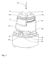
- Fig. 1 shows a perspective sectional view of the clamping device according to the invention in the first embodiment from a first perspective. Shown are two of the four chuck segments 10, 12. These chuck segments 10, 12 are adjacent to one another and arranged so that they are in contact with one of the receiving parts 14, 16. In this case, the first clamping head segment 10 contacts the inner receiving part 14 with the contact surface 10a. The second clamping head segment 12 contacts the outer receiving part 16 with the contact surface 12a. The two receiving parts 14, 16 are formed so that they extend around the entire clamping head.
- the inner receiving part 14 has, in addition to a sliding surface for the first clamping head segment 1, a second sliding surface, not shown in FIG. 1, for a further clamping head segment opposite the first clamping head segment 10.
- the outer receiving part 16 in addition to a sliding surface for the clamping head segment 12 and a second sliding surface, not shown, for a clamping head segment opposite the second clamping head segment 12.
- the two receiving parts 14, 16 are pushed into each other and each have four wedge surfaces, of which only one wedge surface 14a, 16a can be seen in the illustration. These wedge surfaces 14a, 16a are in surface contact with two wedge surfaces 18a, 18b of a wedge element 18.
- the wedge element 18 lies in a groove 20a of a guide disk 20, wherein the wedge element 18 in this guide disk 20 a straight-line translational movement is possible.
- Fig. 2 shows the same section of the first embodiment of the clamping device from a different perspective.
- the two clamping head segments 10, 12. These have a common conical outer surface, which is formed by the sliding surfaces 10a, 12a.
- a movement of the clamping head segments 10, 12 in a clamping direction 22 is made possible by a coupling 24.
- This coupling 24 has a circumferential inwardly facing web 24a, which engages in the grooves 10b, 12b of the clamping head segments 10, 12.
- the receiving parts 14, 16 the conical inner surface formed by the partial areas 16b, 14b, with one of the sliding surfaces 10a, 12a of the clamping head segments 10, 12 is in contact.
- Fig. 3 shows from a corresponding perspective as in Fig. 1, the second embodiment of the clamping device according to the invention.
- the bearing journal 30 is arranged in a not shown radial groove of the guide disc 20.
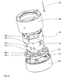
- FIG. 4 shows an exploded view of the first embodiment of the clamping device receptacle of the clamping device.
- Both receiving parts 14, 16 each have four wedge surfaces, wherein the inner receiving part 14 only the two wedge surfaces 14a, 14c can be seen.
- outer receiving part 16 the two wedge surfaces 16a, 16c can be seen.
- these wedge surfaces come into contact with corresponding wedge surfaces 18a, 18b of the wedge elements 18.
- a total of four pieces of these wedge elements 18 are provided, which are guided in grooves 20a of the guide letter 20.
- a housing 26 and a spindle flange 28 can be seen.
- the guide plate 20 is fixedly connected to the spindle flange 28 and the housing 26.
- the two receiving parts 14, 16 have in and against the clamping direction 22 game, with their displacement on the wedge elements 18 is in a fixed context.
- the clamping of a workpiece is as follows.
- the coupling 24 is pulled in the tensioning direction 22.
- This also leads to a movement in the same direction through the clamping head segments 10, 12. Since these are with their sliding surfaces 10a, 12a with the sliding surfaces 14b, 16b of the receiving parts 14, 16 in contact, the clamping head segments 10, 12 and the other two clamping head segments, not shown, simultaneously moved towards each other radially.
- the first of the clamping head segments 10, 12 comes into contact with the workpiece, it clamps this together with the opposite clamping head segment.
- the clamping head segment 10 and the clamping head segment lying opposite it first come into contact with the workpiece, they clamp it firmly.
- a further relative movement between the clamping head segment 10 and the receiving part 14 is no longer possible. Therefore, it is caused by a further train on the clutch 24, that the clamping head segment 10 is pulled together with the receiving part 14 in the clamping direction 22.
- the clamping head segment 12 is accelerated radially to the workpiece by further pulling on the coupling 24, because while the clamping head segment 12 is moved further with the sliding surface 12a in the clamping direction, the receiving part 16 is displaced counter to the clamping direction.
- the train on the clutch 24 then ends, although the clamping head segment 12 and the other clamping head segment, not shown, opposite it comes into contact with the workpiece.
- the workpiece is then firmly clamped on all four sides and machining is possible in an ideal manner and width.
Landscapes
- Engineering & Computer Science (AREA)
- Mechanical Engineering (AREA)
- Jigs For Machine Tools (AREA)
- Machine Tool Units (AREA)
- Clamps And Clips (AREA)
- Surgical Instruments (AREA)
- Mechanical Treatment Of Semiconductor (AREA)
Description
- Die Erfindung betrifft eine Spanneinrichtung mit den Merkmalen des Oberbegriffs des Anspruchs 1 und wie z.B. ans FR-A-502 015 bekannt ist.
- Spanneinrichtungen zum Einspannen von Werkstücken, beispielsweise in Werkzeugmaschinen, sind bekannt. Sie sorgen dafür, dass ein Werkstück sicher und spielfrei gehalten wird. Für diesen Zweck verfügen Spanneinrichtungen über Spannsegmente, die mit Hilfe eines dafür vorgesehenen Mechanismus zusammengedrückt werden und dabei das Werkstück festklemmen. Bei heute üblichen Spanneinrichtungen werden, beispielsweise mittels eines Spannzylinders, alle Spannsegmente miteinander bewegt. Dies bringt den wesentlichen Nachteil mit sich, dass bei einem beispielsweise vierteiligen Spannkopf in dem Augenblick des Schließens, wenn das erste Paar der Spannsegmente an dem Werkstück anliegt, eine weitere Bewegung des noch nicht anliegenden Spannsegmentpaares nicht mehr möglich ist. Dies wirkt sich insbesondere bei Mehrkantprofilen mit größeren Toleranzen negativ aus.
- Der Erfindung liegt die Aufgabe zugrunde, eine eingangs genannte Spanneinrichtung zu schaffen, mit der die Nachteile des Standes der Technik vermieden werden können und insbesondere ein sicherer Halt des Werkstücks durch alle Spannsegmente gewährleistet werden kann.
- Gelöst wird diese Aufgabe durch eine Spanneinrichtung mit den Merkmalen des Anspruchs 1. Vorteilhafte sowie bevorzugte Ausgestaltung der Erfindung sind in den weiteren Ansprüchen angegeben und werden im folgenden näher erläutert. Der Wortlaut der Ansprüche wird durch ausdrückliche Bezugnahme zum Inhalt der Beschreibung gemacht.
- Erfindungsgemäß weist die Spanneinrichtung mehrere Aufnahmeteile auf, die in Spannrichtung verschiebbar sind und so ausgebildet sind, dass jedes der Aufnahmeteile jeweils ein Spannkopfsegment oder zwei gegenüberliegende Spannkopfsegmente der schrägen Innenfläche aufweist, so dass jedes Aufnahmeteil jeweils die Gleitflächen für ein Spannkopfsegment bzw. zwei sich gegenüberliegende Spannkopfsegmente aufweist. Darüber hinaus sind Mittel zur Kraftumlenkung vorgesehen, die in Reaktion auf eine Verschiebung eines Aufnahmeteils in oder entgegen der Spannrichtung eine Verschiebung der anderen Aufnahmeteile in eine entgegengesetzte Richtung bewirken.
- Eine solche Spanneinrichtung erlaubt das sichere Einspannen von Werkstücken, auch dann, wenn die Werkstücke ein gegenüber einem Idealzustand abweichenden Querschnitt aufweisen. So ist es beispielsweise mit einer erfindungsgemäßen Spanneinrichtung mit vier Spannkopfsegmenten möglich, ein Werkstück mit rechteckigem Querschnitt einzuspannen, so dass die Spannkopfsegmente an allen vier Seiten fest anliegen und das Werkstück insgesamt einen sehr sicheren Halt hat. Der Ablauf des Spannens gestaltet sich dabei folgendermaßen. Der Spannkopf mit den Spannkopfsegmenten wird in die aus Aufnahmeteilen bestehende Spannmittelaufnahme verschoben. Die Spannkopfsegmente werden dabei durch das Gleiten auf den schrägen Innenflächen der Aufnahmeteile der Spannmittelaufnahme aufeinander zu gedrückt. Dies geschieht, bis das erste Spannkopfsegment mit dem Werkstück in Berührung gerät. Beim weiteren Zusammenziehen wird das Werkstück mit dem Spannkopfsegment, mit dem es in Berührung steht, in Richtung eines oder mehrerer gegenüberliegende Spannkopfsegmente gedrückt. Wenn es mit diesem oder diesen Spannkopfsegmenten zur Berührung kommt, ist keine weitere Verschiebung dieser Spannkopfsegmente relativ zu ihren jeweiligen zugeordneten Aufnahmeteile möglich. Bei einer weiteren Verschiebung des Spannkopfs in der Spanneinrichtung werden deshalb die entsprechenden Aufnahmeteile der Spannmittelaufnahme mit verschoben. Durch die Mittel zur Kraftumlenkung führt dies dazu, dass jene Aufnahmeteile, deren Spannkopfsegmente noch nicht mit dem Werkstück in Kontakt stehen, in entgegengesetzte Richtung verschoben werden. Dies geschieht bis die nächsten Spannkopfsegmente in Kontakt mit dem Werkstück gelangen. Auf diesem Wege werden im Zuge des Spannvorgangs nacheinander alle Spannkopfsegmente von ihren entsprechenden Aufnahmeteilen gegen das Werkstück gedrückt, bis kein weiteres Verschieben des Spannkopfs in der Spannmittelkaufnahme möglich ist. Die erfindungsgemäße Spanneinrichtung erlaubt also das sichere und spielfreie Einspannen auch von solchen Werkstücken, deren Querschnitt bei herkömmlichen Spanneinrichtungen bislang nur das Einspannen mit zwei Spannkopfsegmenten erlaubte. Die Mittel zur Kraftumlenkung können beispielsweise mechanischer oder hydraulischer Natur sein.
- In einer Weiterbildung der Erfindung ist die Anzahl der Spannkopfsegmente gerade und für jeweils zwei gegenüberliegende Spannkopfsegmente ist ein Aufnahmeteil vorgesehen, welches je eine Gleitfläche für jeweils ein Spannkopfsegment aufweist. Eine solche Ausgestaltung der Erfindung führt dazu, dass die Spannkopfsegmente immer paarweise an dem Werkstück angreifen. Darüber hinaus ist diese Ausgestaltung auch bezüglich der Abstützung der auftretenden Kräfte sehr vorteilhaft. Beim Verschieben des Spannkopfs in der Spannmittelaufnahme kommt es zu starken radialen Kräften auf den Gleitflächen, wobei diese Kräfte bei gegenüberliegenden Gleitflächen jeweils gleich groß sind und in entgegengesetzte Richtung wirken. Durch die einteilige Ausführung der Aufnahmeteile für jeweils zwei Gleitflächen können diese Aufnahmeteile die auftretenden Kräfte aufnehmen.
- In einer Weiterbildung der Erfindung weist die Spanneinrichtung zwei Aufnahmeteile und vier Spannkopfsegmente auf. Eine solche Konstellation ist ideal für das Einspannen von Vierkantprofilen. Bei solchen Vierkantprofilen, die von dem Ideal eines quadratischen Querschnitts abweichen, ist ein sicheres Einspannen mit der erfindungsgemäßen Spanneinrichtung möglich. Die Verwendung von nur zwei Aufnahmeteilen ist insbesondere deshalb zweckmäßig, da dies den konstruktiven Aufwand für die Mittel zur Kraftumlenkung deutlich reduziert. Die Mittel müssen so ausgebildet sein, dass ein Verschieben des ersten Aufnahmeteils zu einer entgegengesetzten Verschiebung des anderen Aufnahmeteils führt.
- In einer Weiterbildung der Erfindung sind die Spannkopfsegmente regelmäßig auf einem Kreisbogen angeordnet. Dadurch gewährleistet die Spanneinrichtung einen festen Halt des Werkstücks. Das Werkstück wird von allen Seiten gleichmäßig gehalten.
- In einer Weiterbildung der Erfindung ist die gesamte Innenfläche der Spannmittelaufnahme und die gesamte Außenfläche des Spannkopfs konisch ausgebildet. Die konische Innenfläche der Spannmittelaufnahme wird dabei durch die Teilflächen der verschiedenen Aufnahmeteile gebildet. Die konische Außenfläche des Spannkopfs wird durch die Teilflächen der Spannkopfsegmente gebildet. In Betrieb kann es zu Abweichungen gegenüber der Konizität der Innen- bzw. Außenflächen geben, da sowohl die Aufnahmeteile als auch die Spannkopfsegmente in Spannrichtung gegeneinander verschiebbar sind. Die konische Gestaltung der Innenfläche der Spannmittelaufnahme und der Außenfläche des Spannkopfs ist vor allem unter wirtschaftlichen Gesichtspunkten bezüglich der Fertigung sinnvoll.
- In einer Weiterbildung der Erfindung handelt es sich bei den Mitteln zur Kraftumlenkung um ein Keilgetriebe, welches auf einer zu der Spannrichtung der Spanneinrichtung orthogonalen Ebene bewegliche Keilelemente mit jeweils zwei Keilflächen aufweist. Darüber hinaus weisen die Aufnahmeteile bei dieser Weiterbildung der Erfindung jeweils Keilflächen auf, die mit jeweils einer Keilfläche der Keilelemente korrespondieren, wobei vorzugsweise die Anzahl der Keilelemente gleich der Anzahl der Spannkopfsegmente ist. Ein solches Keilgetriebe stellt einen unkomplizierten und kostengünstig herstellbaren Weg zur Kraftumlenkung dar. Wenn ein Spannkopfsegment am Werkstück angreift und infolgedessen beim weiteren Verschieben des Spannkopfs das dem Spannkopfsegment zugeordnete Aufnahmeteil gemeinsam mit dem Spannkopfsegment in Spannrichtung verschoben wird, führt diese Verschiebung zu einer Verschiebung von einem oder mehreren Keilelementen in einer zur Spannrichtung orthogonalen Ebene. Die Verschiebung dieser Keilelemente führt dazu, dass andere Aufnahmeteile, deren Spannkopfsegmente noch nicht mit dem Werkstück in Kontakt sind, in entgegengesetzte Richtung bezogen auf das die Verschiebung verursachende Aufnahmeteil bewegt werden. Die Keilelemente sind dabei vorzugsweise so angeordnet, dass sie jeweils benachbart angeordnete Aufnahmeteile kinematisch miteinander verbinden. Besonders zweckmäßig ist die Verwendung eines Keilgetriebes für die Kraftumlenkung bei Spanneinrichtungen mit zwei Aufnahmeteilen und vier Spannkopfsegmenten. In einem solchen Fall ist es zweckmäßig, vier Keilelemente vorzusehen, so dass die Kraftübertragung von einem auf das andere Aufnahmeteil sehr gleichmäßig und ohne die Gefahr des Verkantens erfolgt.
- In einer Weiterbildung der Erfindung sind die Keilelemente symmetrische ausgebildet und der Winkel der Keilflächen beträgt vorzugsweise jeweils 45°. Eine symmetrische Gestaltung der Keilelemente führt dazu, dass die Kraftumlenkung zwischen zwei Aufnahmeteilen gleichermaßen in beide Richtungen möglich ist. Dadurch ist es unerheblich, welche Spannkopfsegmente zuerst am Werkstück anliegen. Der bevorzugte Teilflächenwinkel von 45° ergibt sich rechnerisch als Ideal bezüglich der Reibungsverluste. Bei einem zugrunde gelegten Reibungskoeffizienten von 0,1 führt ein Keilflächenwinkel von 45° dazu, dass deutlich über 40% der Kraft des Aufnahmeteils, welches in Richtung des Keilelements gedrückt wird, auf das vom Keilelement verschobene Aufnahmeteil übertragen wird.
- In einer Weiterbildung der Erfindung sind die Keilelemente asymmetrisch ausgebildet, und die beiden Keilflächen aller Keilelemente weisen jeweils unterschiedliche Winkel auf. Die Verwendung solcher asymmetrischer Keilelemente ist vor allen Dingen dann zweckmäßig, wenn bekannt ist, welche Spannkopfsegmente zuerst in Berührung mit dem Werkstück kommen. Durch eine darauf angepasste Winkel der Keilflächen ist es möglich, eine bessere Kraftumlenkung zwischen den Aufnahmeteilen zu erreichen.
- In einer Weiterbildung der Erfindung ist eine Führung, insbesondere in einer Scheibe, für die Keilelemente vorgesehen, vorzugsweise in Form von nutenartigen Vertiefungen. Durch eine solche Führung werden die Freiheitsgrade des Keilelements auf eine einfache Translation beschränkt. Das Keilelement wird sicher geführt und kann bei einer Beaufschlagung durch eine Kraft nicht in eine ungewollte Richtung ausweichen. Besonders vorteilhaft ist eine Führung, die auch das Herausfallen des Keilelements aus der Spanneinrichtung verhindert. Besonders zweckmäßig ist die Führung in Form von Nuten, in die die Keilelemente mittels dafür vorgesehener Führungsabschnitte eingreifen.
- In einer Weiterbildung der Erfindung ist die Führung der Keilelemente so ausgebildet, dass die Keilelemente auf einer kreisbogenförmigen Bahn äquidistant zu einer Mittelachse der Spanneinrichtung geführt werden, insbesondere als kreisbogenartige Vertiefung.
- In einer Weiterbildung der Erfindung ist die Führung der Keilelemente gerade ausgebildet. Eine solche Führung ist fertigungstechnisch einfach herzustellen und weist eine geringe Störanfälligkeit auf. Darüber hinaus ist eine flächige Berührung zwischen den Aufnahmeteilen und den Keilelementen bei einer gleichbleibenden Ausrichtung der Keilelemente durch eine gerade Führung gegeben. Im Gegensatz zu Keilelementen, deren Ausrichtung sich infolge einer gebogenen Führung abhängig von der Stellung der Aufnahmeteile ändert, und deren Keilflächen deshalb eine kompliziert herzustellende Form aufweisen müssen, können die Keilflächen bei bezüglich der Ausrichtung unveränderten Keilelementen plan ausgebildet sein.
- In einer Weiterbildung der Erfindung weisen die Mitteln zur Kraftumlenkung einen Waagebalken auf, der um eine orthogonal zur Spannrichtung ausgerichtete Achse kippbar angeordnet ist oder sich darum drehen kann. Wenn ein erstes Aufnahmeteil in Spannrichtung gedrückt wird, drückt es auf eine Seite des Waagebalkens, so dass dieser um die Achse gekippt wird und damit mittels der entgegengesetzten Seite des Waagebalkens die Kraft auf ein zweites Aufnahmeteil leitet, welches dadurch entgegen der Spannrichtung verschoben wird. Die Kippachse ist vorzugsweise durch einen Lagerzapfen realisiert, dessen Außenradius mit dem Innenradius einer Nut des Waagebalkens übereinstimmt. Zweckmäßig ist auch eine einteilige Ausführung eines Waagebalkens mit einem in Spannrichtung weisenden kreisbogenabschnittsförmigen, abgerundeten oder spitzenförmigen Abschnitt, der im direkten Kontakt mit einer Gegenfläche steht, so dass der Waagebalken mit diesem Abschnitt auf der Gegenfläche abrollen und dadurch kippen kann.
- In einer Weiterbildung der Erfindung sind Kugeln als Mittel zur Kraftumlenkung vorgesehen, welche in einem oder mehreren, vorzugsweise U-förmigen, Kanälen angeordnet sind. Wenn ein Aufnahmeteil nach unten gedrückt wird, so drückt es auf eine erste Kugel, die über weitere Kugeln die Kraft weitergibt. Die Kugeln sind in Kanälen angeordnet, die von einem Aufnahmeteil zu einem anderen führen. Die Kraft wird über diese Kugeln weiter geführt, so dass sie am Ende des Kanals auf ein zweites Aufnahmeteil drückt, welches infolge dieser Kraft in bezüglich des ersten Aufnahmeteils entgegengesetzter Richtung verschoben wird.
- In einer Weiterbildung der Erfindung sind elastische Verbindungselemente vorgesehen, mittels derer jedes Spannkopfsegment mit seinen beiden Nachbar-Spannkopfsegmenten verbunden ist. Die Spannkopfsegmente bilden so eine fest verbundene Einheit eines Spannkopfs. Die elastischen Verbindungselemente sorgen für Halt und verhindern, dass ein einzelnes Spannkopfelement sich aus der Spanneinrichtung löst. Darüber hinaus können die elastischen Verbindungselemente dafür sorgen, dass die Spannkopfsegmente beim Öffnen der Spanneinrichtung wieder auseinandergedrückt werden. Zu diesem Zweck sind die elastischen Verbindungselemente so ausgebildet, dass sie im geöffneten Zustand der Spanneinrichtung entspannt sind. Beim Spannen der Spanneinrichtung werden auch die elastischen Verbindungselemente gespannt. Vorteilhaft an der Verwendung elastischer Verbindungselemente ist darüber hinaus, dass der Spannkopf so eine Einheit bildet, wodurch Handhabung und insbesondere Montage deutlich erleichtert wird.
- In einer Weiterbildung der Erfindung sind in einem umlaufenden Spalt zwischen den in Spannrichtung gegeneinander verschiebbaren Aufnahmeteilen der Spannmittelaufnahme Dichtmittel vorgesehen. Die Dichtmittel verhindern das Eindringen von Verunreinigungen, Ölen oder Kühlflüssigkeit. Besonders gut sind solche Dichtmittel zu realisieren, wenn Aufnahmeteile mit jeweils zwei gegenüberliegenden Gleitflächen verwendet werden. Solche Aufnahmeteile sind zweckmäßigerweise um den darin angeordneten Spannkopf geschlossen.
- Diese und weitere Merkmale von bevorzugten Weiterbildungen der Erfindung gehen außer aus den Ansprüchen auch aus der Beschreibung und den Zeichnungen hervor, wobei die einzelnen Merkmale jeweils für sich allein oder zu mehreren in Form von Unterkombinationen bei einer Ausführungsform der Erfindung und auf anderen Gebieten verwirklicht sein und vorteilhafte sowie für sich schutzfähige Ausführungen darstellen können, für die hier Schutz beansprucht wird. Die Unterteilung der Anmeldung in einzelne Abschnitte sowie Zwischen-Überschriften beschränkt die unter diesen gemachten Aussagen nicht in ihrer Allgemeingültigkeit.
- Ausführungsformen der Erfindung mit einer Spannmittelaufnahme aus zwei Aufnahmeteilen und insgesamt vier Spannkopfsegmenten sind in den Zeichnungen schematisch dargestellt und werden im folgenden näher erläutert. In den Zeichnungen zeigen:
- Fig. 1 und 2
- eine geschnittene Darstellung der ersten Ausführungsform der zusammengebauten Spanneinrichtung aus zwei verschiedenen Perspektiven,
- Fig. 3
- eine geschnittene Darstellung der zweiten Ausführungsform der zusammengebauten Spanneinrichtung und
- Fig. 4
- eine Explosionsdarstellung der ersten Ausführungsform der Spannmittelaufnahme ohne Spannkopf.
- Fig. 1 zeigt eine perspektivische geschnittene Ansicht der erfindungsgemäßen Spanneinrichtung in der ersten Ausführungsform aus einer ersten Perspektive. Dargestellt sind zwei der vier Spannkopfsegmente 10, 12. Diese Spannkopfsegmente 10, 12 sind einander benachbart und so angeordnet, dass sie mit jeweils einem der Aufnahmeteile 14, 16 in Berührung sind. Dabei berührt das erste Spannkopfsegment 10 das innere Aufnahmeteil 14 mit der Kontaktfläche 10a. Das zweite Spannkopfsegment 12 berührt das äußere Aufnahmeteil 16 mit der Kontaktfläche 12a. Die beiden Aufnahmeteile 14, 16 sind so ausgebildet, dass sie um den gesamten Spannkopf herumreichen. Das innere Aufnahmeteil 14 weist neben einer Gleitfläche für das erste Spannkopfsegment 1 auch eine in Fig. 1 nicht dargestellte zweite Gleitfläche für ein den ersten Spannkopfsegment 10 gegenüberliegendes weiteres Spannkopfsegment auf. In ähnlicher Art und Weise weist das äußere Aufnahmeteil 16 neben einer Gleitfläche für das Spannkopfsegment 12 auch eine nicht dargestellte zweite Gleitfläche für ein den zweiten Spannkopfsegment 12 gegenüberliegendes Spannkopfsegment auf. Die beiden Aufnahmeteile 14, 16 sind ineinander geschoben und weisen jeweils vier Keilflächen auf, von denen in der Darstellung jeweils nur eine Keilfläche 14a, 16a zu erkennen ist. Diese Keilflächen 14a, 16a befinden sich in flächigem Kontakt mit zwei Keilflächen 18a, 18b eines Keilelements 18. Das Keilelement 18 liegt in einer Nut 20a einer Führungsscheibe 20, wobei dem Keilelement 18 in dieser Führungsscheibe 20 eine gradlinige translatorische Bewegung möglich ist.
- Fig. 2 zeigt den gleichen Schnitt auf die erste Ausführungsform der Spanneinrichtung aus anderer Perspektive. Zu erkennen sind die beiden Spannkopfsegmente 10, 12. Diese weisen eine gemeinsame konusförmige Außenfläche auf, die von den Gleitflächen 10a, 12a gebildet wird. Eine Bewegung der Spannkopfsegmente 10, 12 in eine Spannrichtung 22 wird durch eine Kupplung 24 ermöglicht. Diese Kupplung 24 weist einen umlaufenden nach innen gewandten Steg 24a auf, der in die Nuten 10b, 12b der Spannkopfsegmente 10, 12 greift. Zu erkennen sind darüber hinaus die Aufnahmeteile 14, 16, deren konische Innenfläche, gebildet von den Teilbereichen 16b, 14b, mit jeweils einer der Gleitflächen 10a, 12a der Spannkopfsegmente 10, 12 in Berührung steht.
- Fig. 3 zeigt aus einer entsprechenden Perspektive wie in Fig. 1 die zweite Ausführungsform der erfindungsgemäßen Spanneinrichtung. Diese unterscheidet sich von der in Fig. 1 und 2 dargestellten ersten Ausführungsform dadurch, dass statt der Nut 20a in der Führungsscheibe 20 und dem Keilelement 18 ein Lagerzapfen 30 sowie eine Waagebalken 28 vorgesehen sind. Der Lagerzapfen 30 ist in einer nicht dargestellten radialen Nut der Führungsscheibe 20 angeordnet. Auf dem Lagerzapfen 30 ist der Waagebalken 28 angeordnet. Dieser weist zwei Kontaktflächen 30a und 30b auf, die sich jeweils mit einem der in Spannrichtung 22 weisenden Enden 14d, 16d der beiden Aufnahmeteile 14,16 in Berührung befinden.
- Fig. 4 zeigt eine Explosionsdarstellung der ersten Ausführungsform der Spannmittelaufnahme der Spanneinrichtung. Zu erkennen sind die beiden Aufnahmeteile 14, 16 sowie die Art und Weise in der das innere Aufnahmeteil 14 in das äußere Aufnahmeteil 16 geschoben ist. Beide Aufnahmeteile 14, 16 verfügen über jeweils vier Keilflächen, wobei beim inneren Aufnahmeteil 14 nur die beiden Keilflächen 14a, 14c zu erkennen sind. Beim äußeren Aufnahmeteil 16 sind die beiden Keilflächen 16a, 16c zu erkennen. Diese Keilflächen kommen beim Zusammenbau in Berührung mit entsprechenden Keilflächen 18a, 18b der Keilelemente 18. Von diesen Keilelementen 18 sind insgesamt vier Stück vorgesehen, welche in Nuten 20a der Führungsschreibe 20 geführt werden. Darüber hinaus ist ein Gehäuse 26 sowie ein Spindelflansch 28 zu sehen. Die Führungsscheibe 20 wird mit dem Spindelflansch 28 und dem Gehäuse 26 fest verbunden. Die beiden Aufnahmeteile 14, 16 haben in und entgegen der Spannrichtung 22 Spiel, wobei ihre Verschiebung über die Keilelemente 18 in einem festen Zusammenhang steht.
- Das Einspannen eines Werkstücks läuft folgendermaßen ab. Die Kupplung 24 wird in Spannrichtung 22 gezogen. Dadurch kommt es ebenfalls zu einer Bewegung in gleicher Richtung durch die Spannkopfsegmente 10, 12. Da diese mit ihren Gleitflächen 10a, 12a mit den Gleitflächen 14b, 16b der Aufnahmeteile 14, 16 in Kontakt stehen, werden die Spannkopfsegmente 10, 12 sowie die anderen beiden nicht dargestellten Spannkopfsegmente gleichzeitig radial aufeinander zu bewegt. Wenn das erste der Spannkopfsegmente 10, 12 mit dem Werkstück in Berührung kommt, klemmt es dieses zusammen mit dem ihm gegenüber liegenden Spannkopfsegment ein. Für den beispielhaft angenommenen Fall, dass das Spannkopfsegment 10 sowie das ihm gegenüber liegenden Spannkopfsegment zuerst mit dem Werkstück in Berührung kommen, klemmen diese es fest. Infolgedessen ist eine weitere relative Bewegung zwischen dem Spannkopfsegment 10 und dem Aufnahmeteil 14 nicht mehr möglich. Deshalb wird durch einen weiteren Zug an der Kupplung 24 verursacht, dass das Spannkopfsegment 10 zusammen mit dem Aufnahmeteil 14 in Spannrichtung 22 gezogen wird.
- Bei der in den Fig. 1, 2 und 4 dargestellten ersten Ausführungsform führt dies dazu, dass das Keilelement 18 bezüglich der Perspektive von Fig. 1 nach rechts verschoben wird und dabei das Aufnahmeteil 16 entgegen der Spannrichtung 22 verschiebt. Bei der in Fig. 3 dargestellten zweiten Ausführungsform wird der Waagebalken auf der linken Seite in die Spannrichtung 22 gedrückt, wodurch die rechte Seite eine Kraft entgegen der Spannrichtung 22 auf das Aufnahmeteil 16 ausübt und dieses dadurch verschiebt. Beide Ausführungsformen erzielen den Effekt, dass eine Verschiebung des einen Aufnahmeteils in Spannrichtung 22 eine gleichzeitige Verschiebung des anderen Aufnahmeteils entgegen der Spannrichtung verursacht. In der Konsequenz wird das Spannkopfsegment 12 durch weiteren Zug an der Kupplung 24 beschleunigt radial auf das Werkstück zu bewegt, denn während das Spannkopfsegment 12 mit der Gleitfläche 12a in Spannrichtung weitergezogen wird, wird das Aufnahmeteil 16 entgegen der Spannrichtung verschoben. Der Zug an der Kupplung 24 endet dann, wenn auch das Spannkopfsegment 12 sowie das nicht dargestellte ihm gegenüber liegende weitere Spannkopfsegment mit dem Werkstück in Berührung kommt. Das Werkstück ist dann von allen vier Seiten fest eingespannt und eine Bearbeitung ist in idealer Art und Weite möglich.
Claims (15)
- Spanneinrichtung mit einer Spannmittelaufnahme und einem darin angeordneten Spannkopf, der mehrere Spannkopfsegmente (10, 12) aufweist und der in einer Spannrichtung (22) gegenüber der Spannmittelaufnahme verschiebbar ist, wobei die Spannmittelaufnahme eine schräge Innenfläche (14b, 16b) und die Spannkopfsegmente (10, 12) schräge Außenflächen (10a, 12a) aufweisen, so dass die Außenflächen (10a, 12a) der Spannkopfsegmente (10, 12) beim Verschieben des Spannkopfs in die Spannmittelaufnahme auf der Innenfläche (14b, 16b) der Spannmittelaufnahme in Spannrichtung (22) gleiten und die Spannkopfsegmente (10, 12) dadurch zusammengedrückt werden,
dadurch gekennzeichnet, dass
die Spannmittelaufnahme mehrere Aufnahmeteile (14, 16) aufweist, die in Spannrichtung (22) verschiebbar sind und so ausgebildet sind, dass jedes der Aufnahmeteile (14, 16) jeweils ein Segment oder zwei gegenüberliegende Segmente der schrägen Innenfläche (14b, 16b) aufweist, so dass jedes Aufnahmeteil jeweils die Gleitflächen (14b, 16b) für ein Spannkopfsegment (10, 12) beziehungsweise zwei sich gegenüberliegende Spannkopfsegmente (10, 12) aufweist, und dass Mittel (18) zur Kraftumlenkung vorgesehen sind, die in Reaktion auf eine Verschiebung eines Aufnahmeteils (14, 16) in oder entgegen der Spannrichtung (22) eine Verschiebung der anderen Aufnahmeteile (16, 14) in eine entgegengesetzte Richtung bewirken. - Spanneinrichtung gemäß Anspruch 1, dadurch gekennzeichnet, dass die Anzahl der Spannkopfsegmente (10, 12) gerade ist und für jeweils zwei gegenüberliegende Spannkopfsegmente (10, 12) ein Aufnahmeteil (14, 16) vorgesehen ist, welches je eine Gleitfläche (14b, 16b) für jeweils ein Spannkopfsegment (10, 12) aufweist.
- Spanneinrichtung gemäß Anspruch 2, dadurch gekennzeichnet, dass sie zwei Aufnahmeteile (14, 16) und vier Spannkopfsegmente (10, 12) aufweist.
- Spanneinrichtung gemäß einem der vorstehenden Ansprüche, dadurch gekennzeichnet, dass die Spannkopfsegmente (10, 12) regelmäßig auf einem Kreisbogen angeordnet sind.
- Spanneinrichtung gemäß einem der vorstehenden Ansprüche, dadurch gekennzeichnet, dass die gesamte Innenfläche (14b, 16b) der Spannmittelaufnahme und die gesamte Außenfläche (10a, 12a) des Spannkopfs konisch ausgebildet sind.
- Spanneinrichtung gemäß einem der vorstehenden Ansprüche, dadurch gekennzeichnet, dass die Mittel zur Kraftumlenkung ein Keilgetriebe aufweisen, welches auf einer zu der Spannrichtung (22) der Spanneinrichtung orthogonalen Ebene bewegliche Keilelemente (18) mit jeweils zwei Keilflächen (18a, 18b) aufweist, und dass die Aufnahmeteile (14, 16) jeweils Keilflächen (14a, 14c, 16a, 16c) aufweisen, die mit jeweils einer Keilfläche (18a, 18b) der Keilelemente (18) korrespondieren, wobei vorzugsweise die Anzahl der Keilelemente (18) gleich der Anzahl der Spannkopfsegmente (10, 12) ist.
- Spanneinrichtung gemäß Anspruch 6, dadurch gekennzeichnet, dass die Keilelemente (18) symmetrisch ausgebildet sind, und vorzugsweise der Winkel der Keilflächen (18a, 18b) jeweils 45° beträgt.
- Spanneinrichtung gemäß Anspruch 6, dadurch gekennzeichnet, dass die Keilelemente asymmetrisch ausgebildet sind und die beiden Keilflächen aller Keilelemente jeweils unterschiedliche Winkel aufweisen.
- Spanneinrichtung gemäß einem der Ansprüche 6 bis 8, dadurch gekennzeichnet, dass eine Führung (20a) für die Keilelemente (18) vorgesehen ist, vorzugsweise in Form von nutenartigen Vertiefungen, insbesondere in einer Scheibe (20).
- Spanneinrichtung gemäß Anspruch 9, dadurch gekennzeichnet, dass die Führung der Keilelemente so ausgebildet ist, dass die Keilelemente auf einer kreisbogenförmigen Bahn äquidistant zu einer Mittelachse der Spanneinrichtung geführt werden, insbesondere als kreisbogenartige Vertiefung.
- Spanneinrichtung gemäß Anspruch 9, dadurch gekennzeichnet, dass die Führung (20a) der Keilelemente (18) gerade ausgebildet ist.
- Spanneinrichtung gemäß einem der Ansprüche 1 bis 5, gekennzeichnet durch Kugeln als Mittel zur Kraftumlenkung, welche in einem oder mehreren, vorzugsweise U-förmigen, Kanälen angeordnet sind.
- Spanneinrichtung gemäß einem der Ansprüche 1 bis 5, dadurch gekennzeichnet, dass die Mittel zur Kraftumlenkung einen Waagebalken (28) aufweisen, der um eine orthogonal zur Spannrichtung (22) ausgerichtete Achse kippbar oder drehbar angeordnet ist.
- Spanneinrichtung gemäß einem der vorstehenden Ansprüche, gekennzeichnet durch elastische Verbindungselemente, mittels derer jedes Spannkopfsegment (10, 12) mit seinen beiden Nachbar-Spannkopfsegmenten verbunden ist.
- Spanneinrichtung gemäß einem der vorstehenden Ansprüche, dadurch gekennzeichnet, dass in einem umlaufenden Spalt zwischen den in Spannrichtung (22) gegeneinander verschiebbaren Aufnahmeteilen (14, 16) der Spannmittelaufnahme Dichtmittel vorgesehen sind.
Applications Claiming Priority (2)
| Application Number | Priority Date | Filing Date | Title |
|---|---|---|---|
| DE102004001839A DE102004001839A1 (de) | 2004-01-07 | 2004-01-07 | Spanneinrichtung |
| PCT/EP2004/014792 WO2005065871A1 (de) | 2004-01-07 | 2004-12-29 | Spanneinrichtung |
Publications (2)
| Publication Number | Publication Date |
|---|---|
| EP1704010A1 EP1704010A1 (de) | 2006-09-27 |
| EP1704010B1 true EP1704010B1 (de) | 2007-05-16 |
Family
ID=34716512
Family Applications (1)
| Application Number | Title | Priority Date | Filing Date |
|---|---|---|---|
| EP04804378A Expired - Lifetime EP1704010B1 (de) | 2004-01-07 | 2004-12-29 | Spanneinrichtung |
Country Status (5)
| Country | Link |
|---|---|
| EP (1) | EP1704010B1 (de) |
| AT (1) | ATE362412T1 (de) |
| DE (2) | DE102004001839A1 (de) |
| TW (1) | TWI337917B (de) |
| WO (1) | WO2005065871A1 (de) |
Families Citing this family (4)
| Publication number | Priority date | Publication date | Assignee | Title |
|---|---|---|---|---|
| DE102008064525A1 (de) | 2008-12-18 | 2010-07-01 | Hainbuch Gmbh Spannende Technik | Spanneinrichtung sowie Verfahren zum Verbinden einer Spannbacke mit einer Spanneinrichtung |
| TWI400148B (zh) * | 2009-06-15 | 2013-07-01 | Hon Hai Prec Ind Co Ltd | 固定裝置 |
| DE102013201231B3 (de) | 2013-01-25 | 2014-02-13 | Volker Henke | Ausgleichsspannfutter |
| PL3028794T3 (pl) | 2014-12-04 | 2019-09-30 | Hvm Technology Gmbh | Uchwyt zaciskowy mocujący |
Family Cites Families (8)
| Publication number | Priority date | Publication date | Assignee | Title |
|---|---|---|---|---|
| FR502015A (fr) * | 1918-08-03 | 1920-05-01 | Tangent Tool Company Cosmos Lt | Mandrin de support pour forets, alésoirs et autres outils analogues |
| US1582719A (en) * | 1925-08-25 | 1926-04-27 | Wilkening Mfg Co | Piston-ring-contracting apparatus |
| DE3425873A1 (de) * | 1984-07-13 | 1986-01-23 | Fa. Robert Schröder, 5600 Wuppertal | Dreibackenbohrfutter, insbesondere fuer handbohrmaschinen |
| DD284349A7 (de) * | 1988-11-16 | 1990-11-14 | �������@������������@��k�� | Vorrichtung zum spannen eines werkzeuges oder werkstueckes vorzugsweise in einer arbeitsspindel |
| DE19703354C1 (de) * | 1997-01-30 | 1998-03-12 | Optima Spanntechnik Gmbh | Spannvorrichtung zum Spannen zweier voneinander lösbarer Maschinenteile, insbesondere zum Festspannen eines Werkzeuges oder Werkstückes an einer Bearbeitungsmaschine |
| DE19843416C2 (de) * | 1998-09-22 | 2001-07-19 | Rampp Engineering Gmbh & Co Kg | Spannvorrichtung |
| DE10055257C2 (de) * | 2000-11-08 | 2003-08-14 | Man Technologie Gmbh | Vorrichtung zum Einspannen von hohlprofilierten Werkstücken und Verfahren zur Montage von segmentartig ausgebildeten Werkstücken sowie deren Verwendung |
| DE10055591A1 (de) * | 2000-11-09 | 2002-05-23 | Voith Paper Patent Gmbh | Klemmvorrichtung |
-
2004
- 2004-01-07 DE DE102004001839A patent/DE102004001839A1/de not_active Withdrawn
- 2004-12-29 AT AT04804378T patent/ATE362412T1/de not_active IP Right Cessation
- 2004-12-29 EP EP04804378A patent/EP1704010B1/de not_active Expired - Lifetime
- 2004-12-29 DE DE502004003849T patent/DE502004003849D1/de not_active Expired - Lifetime
- 2004-12-29 WO PCT/EP2004/014792 patent/WO2005065871A1/de not_active Ceased
-
2005
- 2005-01-07 TW TW094100536A patent/TWI337917B/zh not_active IP Right Cessation
Also Published As
| Publication number | Publication date |
|---|---|
| EP1704010A1 (de) | 2006-09-27 |
| TW200600268A (en) | 2006-01-01 |
| WO2005065871A1 (de) | 2005-07-21 |
| TWI337917B (en) | 2011-03-01 |
| DE502004003849D1 (de) | 2007-06-28 |
| DE102004001839A1 (de) | 2005-08-04 |
| ATE362412T1 (de) | 2007-06-15 |
Similar Documents
| Publication | Publication Date | Title |
|---|---|---|
| CH655038A5 (de) | Bohrhammer fuer bohr- und schlagbohrbetrieb. | |
| EP0401548A1 (de) | Schraubwerkzeugmaschine | |
| DE10140270A1 (de) | Presszange zum Einpressen mehrerer Kerben auf dem Umfang eines Kontaktelementes | |
| DE3513453A1 (de) | Greifvorrichtung mit auswechselbarer greiferbacke | |
| DE202017003037U1 (de) | Präzisionsspannfutter mit bogenförmigen Schienen | |
| EP3064823B1 (de) | Schnellspannvorrichtung zur selbstschliessenden aufnahme eines gegegenstücks | |
| EP3616831B1 (de) | Spannvorrichtung | |
| WO1990000098A1 (de) | Radialpresse für im wesentlichen zylindrische werkstücke | |
| DE102004054177B3 (de) | Spann- oder Greifvorrichtung, insbesondere Linear- oder Zentrischgreifer | |
| DE19605953A1 (de) | Gleitblock für eine Teleskopsäule | |
| DE1627398C3 (de) | Vorrichtung zur Bearbeitung von Rohren und dgl | |
| EP1704010A1 (de) | Spanneinrichtung | |
| DE3300227A1 (de) | Vorrichtung zur loesbaren verbindung von greiferschienenteilen der greiferschienen in einer transfer-presse | |
| EP2198995A1 (de) | Spanneinrichtung sowie Verfahren zum Verbinden einer Spannbacke mit einer Spanneinrichtung | |
| WO2016008625A1 (de) | Werkzeug zum abmanteln eines kabels | |
| CH629991A5 (de) | Klemmvorrichtung fuer die spindelhuelse einer fraes- und bohrspindel. | |
| DE3941935C2 (de) | Spannschloß | |
| EP2027971A2 (de) | Presszange zum radialen Verpressen von Rohren, Rohrstücken und dergleichen | |
| DE3607904C2 (de) | Klebebindemaschine | |
| EP0604887B1 (de) | Nachstellbare Rutschkupplung | |
| EP1253994A1 (de) | Spanneinrichtung | |
| DE19635889A1 (de) | Werkzeugeinheit | |
| EP4104966B1 (de) | Aufspannvorrichtung | |
| EP2848376B1 (de) | Greifeinrichtung | |
| DE102019115019A1 (de) | Orthodontische Dehnschraube |
Legal Events
| Date | Code | Title | Description |
|---|---|---|---|
| PUAI | Public reference made under article 153(3) epc to a published international application that has entered the european phase |
Free format text: ORIGINAL CODE: 0009012 |
|
| 17P | Request for examination filed |
Effective date: 20060523 |
|
| AK | Designated contracting states |
Kind code of ref document: A1 Designated state(s): AT BE BG CH CY CZ DE DK EE ES FI FR GB GR HU IE IS IT LI LT LU MC NL PL PT RO SE SI SK TR |
|
| GRAP | Despatch of communication of intention to grant a patent |
Free format text: ORIGINAL CODE: EPIDOSNIGR1 |
|
| DAX | Request for extension of the european patent (deleted) | ||
| GRAS | Grant fee paid |
Free format text: ORIGINAL CODE: EPIDOSNIGR3 |
|
| GRAA | (expected) grant |
Free format text: ORIGINAL CODE: 0009210 |
|
| AK | Designated contracting states |
Kind code of ref document: B1 Designated state(s): AT BE BG CH CY CZ DE DK EE ES FI FR GB GR HU IE IS IT LI LT LU MC NL PL PT RO SE SI SK TR |
|
| PG25 | Lapsed in a contracting state [announced via postgrant information from national office to epo] |
Ref country code: FI Free format text: LAPSE BECAUSE OF FAILURE TO SUBMIT A TRANSLATION OF THE DESCRIPTION OR TO PAY THE FEE WITHIN THE PRESCRIBED TIME-LIMIT Effective date: 20070516 |
|
| REG | Reference to a national code |
Ref country code: GB Ref legal event code: FG4D Free format text: NOT ENGLISH |
|
| REG | Reference to a national code |
Ref country code: CH Ref legal event code: EP |
|
| REG | Reference to a national code |
Ref country code: IE Ref legal event code: FG4D Free format text: LANGUAGE OF EP DOCUMENT: GERMAN |
|
| REF | Corresponds to: |
Ref document number: 502004003849 Country of ref document: DE Date of ref document: 20070628 Kind code of ref document: P |
|
| PG25 | Lapsed in a contracting state [announced via postgrant information from national office to epo] |
Ref country code: SE Free format text: LAPSE BECAUSE OF FAILURE TO SUBMIT A TRANSLATION OF THE DESCRIPTION OR TO PAY THE FEE WITHIN THE PRESCRIBED TIME-LIMIT Effective date: 20070816 |
|
| PG25 | Lapsed in a contracting state [announced via postgrant information from national office to epo] |
Ref country code: ES Free format text: LAPSE BECAUSE OF FAILURE TO SUBMIT A TRANSLATION OF THE DESCRIPTION OR TO PAY THE FEE WITHIN THE PRESCRIBED TIME-LIMIT Effective date: 20070827 |
|
| PG25 | Lapsed in a contracting state [announced via postgrant information from national office to epo] |
Ref country code: IS Free format text: LAPSE BECAUSE OF FAILURE TO SUBMIT A TRANSLATION OF THE DESCRIPTION OR TO PAY THE FEE WITHIN THE PRESCRIBED TIME-LIMIT Effective date: 20070916 |
|
| NLV1 | Nl: lapsed or annulled due to failure to fulfill the requirements of art. 29p and 29m of the patents act | ||
| PG25 | Lapsed in a contracting state [announced via postgrant information from national office to epo] |
Ref country code: PL Free format text: LAPSE BECAUSE OF FAILURE TO SUBMIT A TRANSLATION OF THE DESCRIPTION OR TO PAY THE FEE WITHIN THE PRESCRIBED TIME-LIMIT Effective date: 20070516 |
|
| GBV | Gb: ep patent (uk) treated as always having been void in accordance with gb section 77(7)/1977 [no translation filed] |
Effective date: 20070516 |
|
| REG | Reference to a national code |
Ref country code: IE Ref legal event code: FD4D |
|
| EN | Fr: translation not filed | ||
| PG25 | Lapsed in a contracting state [announced via postgrant information from national office to epo] |
Ref country code: NL Free format text: LAPSE BECAUSE OF FAILURE TO SUBMIT A TRANSLATION OF THE DESCRIPTION OR TO PAY THE FEE WITHIN THE PRESCRIBED TIME-LIMIT Effective date: 20070516 Ref country code: CZ Free format text: LAPSE BECAUSE OF FAILURE TO SUBMIT A TRANSLATION OF THE DESCRIPTION OR TO PAY THE FEE WITHIN THE PRESCRIBED TIME-LIMIT Effective date: 20070516 Ref country code: SI Free format text: LAPSE BECAUSE OF FAILURE TO SUBMIT A TRANSLATION OF THE DESCRIPTION OR TO PAY THE FEE WITHIN THE PRESCRIBED TIME-LIMIT Effective date: 20070516 Ref country code: PT Free format text: LAPSE BECAUSE OF FAILURE TO SUBMIT A TRANSLATION OF THE DESCRIPTION OR TO PAY THE FEE WITHIN THE PRESCRIBED TIME-LIMIT Effective date: 20071016 Ref country code: DK Free format text: LAPSE BECAUSE OF FAILURE TO SUBMIT A TRANSLATION OF THE DESCRIPTION OR TO PAY THE FEE WITHIN THE PRESCRIBED TIME-LIMIT Effective date: 20070516 Ref country code: IE Free format text: LAPSE BECAUSE OF FAILURE TO SUBMIT A TRANSLATION OF THE DESCRIPTION OR TO PAY THE FEE WITHIN THE PRESCRIBED TIME-LIMIT Effective date: 20070516 Ref country code: BG Free format text: LAPSE BECAUSE OF FAILURE TO SUBMIT A TRANSLATION OF THE DESCRIPTION OR TO PAY THE FEE WITHIN THE PRESCRIBED TIME-LIMIT Effective date: 20070816 |
|
| PG25 | Lapsed in a contracting state [announced via postgrant information from national office to epo] |
Ref country code: LT Free format text: LAPSE BECAUSE OF FAILURE TO SUBMIT A TRANSLATION OF THE DESCRIPTION OR TO PAY THE FEE WITHIN THE PRESCRIBED TIME-LIMIT Effective date: 20070516 Ref country code: SK Free format text: LAPSE BECAUSE OF FAILURE TO SUBMIT A TRANSLATION OF THE DESCRIPTION OR TO PAY THE FEE WITHIN THE PRESCRIBED TIME-LIMIT Effective date: 20070516 |
|
| PLBE | No opposition filed within time limit |
Free format text: ORIGINAL CODE: 0009261 |
|
| STAA | Information on the status of an ep patent application or granted ep patent |
Free format text: STATUS: NO OPPOSITION FILED WITHIN TIME LIMIT |
|
| 26N | No opposition filed |
Effective date: 20080219 |
|
| PG25 | Lapsed in a contracting state [announced via postgrant information from national office to epo] |
Ref country code: GB Free format text: LAPSE BECAUSE OF FAILURE TO SUBMIT A TRANSLATION OF THE DESCRIPTION OR TO PAY THE FEE WITHIN THE PRESCRIBED TIME-LIMIT Effective date: 20070516 Ref country code: IT Free format text: LAPSE BECAUSE OF FAILURE TO SUBMIT A TRANSLATION OF THE DESCRIPTION OR TO PAY THE FEE WITHIN THE PRESCRIBED TIME-LIMIT Effective date: 20070516 Ref country code: GR Free format text: LAPSE BECAUSE OF FAILURE TO SUBMIT A TRANSLATION OF THE DESCRIPTION OR TO PAY THE FEE WITHIN THE PRESCRIBED TIME-LIMIT Effective date: 20070817 |
|
| PG25 | Lapsed in a contracting state [announced via postgrant information from national office to epo] |
Ref country code: RO Free format text: LAPSE BECAUSE OF FAILURE TO SUBMIT A TRANSLATION OF THE DESCRIPTION OR TO PAY THE FEE WITHIN THE PRESCRIBED TIME-LIMIT Effective date: 20070516 |
|
| BERE | Be: lapsed |
Owner name: HAINBUCH G.M.B.H. SPANNENDE TECHNIK Effective date: 20071231 |
|
| PG25 | Lapsed in a contracting state [announced via postgrant information from national office to epo] |
Ref country code: MC Free format text: LAPSE BECAUSE OF NON-PAYMENT OF DUE FEES Effective date: 20071231 Ref country code: FR Free format text: LAPSE BECAUSE OF FAILURE TO SUBMIT A TRANSLATION OF THE DESCRIPTION OR TO PAY THE FEE WITHIN THE PRESCRIBED TIME-LIMIT Effective date: 20080111 |
|
| PG25 | Lapsed in a contracting state [announced via postgrant information from national office to epo] |
Ref country code: BE Free format text: LAPSE BECAUSE OF NON-PAYMENT OF DUE FEES Effective date: 20071231 |
|
| PG25 | Lapsed in a contracting state [announced via postgrant information from national office to epo] |
Ref country code: EE Free format text: LAPSE BECAUSE OF FAILURE TO SUBMIT A TRANSLATION OF THE DESCRIPTION OR TO PAY THE FEE WITHIN THE PRESCRIBED TIME-LIMIT Effective date: 20070516 |
|
| PG25 | Lapsed in a contracting state [announced via postgrant information from national office to epo] |
Ref country code: AT Free format text: LAPSE BECAUSE OF NON-PAYMENT OF DUE FEES Effective date: 20071229 |
|
| PG25 | Lapsed in a contracting state [announced via postgrant information from national office to epo] |
Ref country code: CY Free format text: LAPSE BECAUSE OF FAILURE TO SUBMIT A TRANSLATION OF THE DESCRIPTION OR TO PAY THE FEE WITHIN THE PRESCRIBED TIME-LIMIT Effective date: 20070516 |
|
| REG | Reference to a national code |
Ref country code: CH Ref legal event code: PL |
|
| PG25 | Lapsed in a contracting state [announced via postgrant information from national office to epo] |
Ref country code: LU Free format text: LAPSE BECAUSE OF NON-PAYMENT OF DUE FEES Effective date: 20071229 |
|
| PG25 | Lapsed in a contracting state [announced via postgrant information from national office to epo] |
Ref country code: HU Free format text: LAPSE BECAUSE OF FAILURE TO SUBMIT A TRANSLATION OF THE DESCRIPTION OR TO PAY THE FEE WITHIN THE PRESCRIBED TIME-LIMIT Effective date: 20071117 Ref country code: TR Free format text: LAPSE BECAUSE OF FAILURE TO SUBMIT A TRANSLATION OF THE DESCRIPTION OR TO PAY THE FEE WITHIN THE PRESCRIBED TIME-LIMIT Effective date: 20070516 |
|
| PG25 | Lapsed in a contracting state [announced via postgrant information from national office to epo] |
Ref country code: LI Free format text: LAPSE BECAUSE OF NON-PAYMENT OF DUE FEES Effective date: 20081231 Ref country code: CH Free format text: LAPSE BECAUSE OF NON-PAYMENT OF DUE FEES Effective date: 20081231 |
|
| REG | Reference to a national code |
Ref country code: DE Ref legal event code: R082 Ref document number: 502004003849 Country of ref document: DE Representative=s name: WITTE, WELLER & PARTNER PATENTANWAELTE MBB, DE Ref country code: DE Ref legal event code: R082 Ref document number: 502004003849 Country of ref document: DE Representative=s name: PATENTANWALTSKANZLEI CARTAGENA PARTNERSCHAFTSG, DE |
|
| PGFP | Annual fee paid to national office [announced via postgrant information from national office to epo] |
Ref country code: DE Payment date: 20201223 Year of fee payment: 17 |
|
| REG | Reference to a national code |
Ref country code: DE Ref legal event code: R082 Ref document number: 502004003849 Country of ref document: DE Representative=s name: WITTE, WELLER & PARTNER PATENTANWAELTE MBB, DE |
|
| REG | Reference to a national code |
Ref country code: DE Ref legal event code: R119 Ref document number: 502004003849 Country of ref document: DE |
|
| PG25 | Lapsed in a contracting state [announced via postgrant information from national office to epo] |
Ref country code: DE Free format text: LAPSE BECAUSE OF NON-PAYMENT OF DUE FEES Effective date: 20220701 |