EP1704342B2 - Dispositif de synchronisation d'une boite de vitesses a roues dentees - Google Patents
Dispositif de synchronisation d'une boite de vitesses a roues dentees Download PDFInfo
- Publication number
- EP1704342B2 EP1704342B2 EP05700006A EP05700006A EP1704342B2 EP 1704342 B2 EP1704342 B2 EP 1704342B2 EP 05700006 A EP05700006 A EP 05700006A EP 05700006 A EP05700006 A EP 05700006A EP 1704342 B2 EP1704342 B2 EP 1704342B2
- Authority
- EP
- European Patent Office
- Prior art keywords
- ring
- friction
- annular body
- synchronizer
- driver
- Prior art date
- Legal status (The legal status is an assumption and is not a legal conclusion. Google has not performed a legal analysis and makes no representation as to the accuracy of the status listed.)
- Expired - Lifetime
Links
Images

Classifications
-
- F—MECHANICAL ENGINEERING; LIGHTING; HEATING; WEAPONS; BLASTING
- F16—ENGINEERING ELEMENTS AND UNITS; GENERAL MEASURES FOR PRODUCING AND MAINTAINING EFFECTIVE FUNCTIONING OF MACHINES OR INSTALLATIONS; THERMAL INSULATION IN GENERAL
- F16D—COUPLINGS FOR TRANSMITTING ROTATION; CLUTCHES; BRAKES
- F16D23/00—Details of mechanically-actuated clutches not specific for one distinct type
- F16D23/02—Arrangements for synchronisation, also for power-operated clutches
- F16D23/025—Synchro rings
-
- F—MECHANICAL ENGINEERING; LIGHTING; HEATING; WEAPONS; BLASTING
- F16—ENGINEERING ELEMENTS AND UNITS; GENERAL MEASURES FOR PRODUCING AND MAINTAINING EFFECTIVE FUNCTIONING OF MACHINES OR INSTALLATIONS; THERMAL INSULATION IN GENERAL
- F16D—COUPLINGS FOR TRANSMITTING ROTATION; CLUTCHES; BRAKES
- F16D23/00—Details of mechanically-actuated clutches not specific for one distinct type
- F16D23/02—Arrangements for synchronisation, also for power-operated clutches
- F16D23/04—Arrangements for synchronisation, also for power-operated clutches with an additional friction clutch
- F16D23/06—Arrangements for synchronisation, also for power-operated clutches with an additional friction clutch and a blocking mechanism preventing the engagement of the main clutch prior to synchronisation
- F16D2023/0681—Double cone synchromesh clutches
-
- Y—GENERAL TAGGING OF NEW TECHNOLOGICAL DEVELOPMENTS; GENERAL TAGGING OF CROSS-SECTIONAL TECHNOLOGIES SPANNING OVER SEVERAL SECTIONS OF THE IPC; TECHNICAL SUBJECTS COVERED BY FORMER USPC CROSS-REFERENCE ART COLLECTIONS [XRACs] AND DIGESTS
- Y10—TECHNICAL SUBJECTS COVERED BY FORMER USPC
- Y10T—TECHNICAL SUBJECTS COVERED BY FORMER US CLASSIFICATION
- Y10T74/00—Machine element or mechanism
- Y10T74/19—Gearing
- Y10T74/19219—Interchangeably locked
- Y10T74/19284—Meshing assisters
Definitions
- the invention relates to a synchronizer for a gear change transmission with at least one cone clutch, which has a relative to a hub freely rotatable double cone ring between an inner friction ring and an outer relative to the friction ring axially displaceable synchronizer ring having an annular body with a locking toothing on the outer circumference and a friction surface on the inner circumference and radially inwardly directed driver for the friction ring has.
- the double cone ring is frictionally accelerated by the axial entrainment of the synchronizer ring between the inner friction ring and the outer synchronizer ring and thus the gear wheel rotatably connected to the double cone ring to the rotational speed of the hub, which the subsequent , unobstructed clutch engagement between the Sliding sleeve and the claw ring of the gear wheel allows.
- a arranged on the synchronizer ring, cooperating with the claws of the sliding sleeve locking teeth prevents the sliding sleeve during synchronization can perform the axial coupling movement.
- the invention is therefore the object of a synchronizer of the type described in such a way that simple manufacturing conditions can be ensured without having to fear overuse of the construction parts.
- the invention solves the problem set by the fact that the drivers are provided on a driver ring of at least one sheet metal blank, which is connected to the consisting of a sintered body ring body, and that the driving ring is connected to the annular body while leaving distributed over the circumference radial gaps ,
- the simple condition is created to manufacture the ring body powder metallurgy as a sintered body without having to fear overloading the driver, which are provided on a driver ring of at least one sheet metal blank. It therefore only need the driving ring and the ring body to be connected to each other after their separate production, which does not depend on a special joining technique, if only a corresponding power transmission between the ring body and driving ring is guaranteed.
- the assignment of the driver to a separate driver ring also provides an advantageous condition for the fact that the driver ring is released while leaving distributed over the circumference, radial gaps between driver ring and ring body, what the oil displacement between the friction ring and double cone or friction ring and synchronizer ring on the Facilitated side of the driver and leads to improved cooling over the flow of oil through this column.
- the annular body or the driver ring may have the gap-width-determining connection projections which not only provide connecting surfaces, but also serve as spacers.
- gap width corresponds to the thickness of an adhesion-promoting layer, for example an adhesive or solder layer, provided only in peripheral sections.
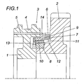
- a jaw clutch 3 is provided between a rotatably seated on a shaft hub 1 and a freely rotatably mounted on this shaft gear 2 of a gear change transmission having an axially displaceably mounted on the hub 1 sliding sleeve 4, with its inner teeth 5 with a claw ring 6 a Coupling body 7 of the gear wheel 2 cooperates.
- a synchronizer is provided which comprises an inner friction ring 8, an outer synchronizer ring 9 and a double cone ring 10.
- the double cone ring 10 is rotatably connected to the gear wheel 2 via drivers 11, which engage in corresponding receptacles 12 of the coupling body 7.
- the synchronizer ring 9, which forms a cone clutch with the friction ring 8 and the double cone ring 10, is axially displaceable relative to the friction ring 8 and coupled to the friction ring 8 via driver 13 for rotational drive.
- the limited compared to the sliding sleeve 4 rotatable synchronizer ring 9 is provided with a locking teeth 14 which with the dog teeth 5 of the sliding sleeve 4 cooperates.
- the synchronizer ring 9 of a ring body 15 and a driver 13 forming driving ring 16 is joined.
- This separation between the annular body 16 and a separate driver ring 16 associated drivers 13 allows advantageously to produce the annular body 15 powder metallurgically as a sintered body, while the driving ring 16 with the drivers 13 consists of a sheet metal blank.
- the advantages of the powder metallurgical production of the annular body 15 can be availed without having to fear an overload of the driver 13, which are indeed connected to a driver ring 16 of a sheet metal blank. It only needs to be taken care of for a corresponding connection between the annular body 15 and the driving ring 16, for which both positive and cohesive connections can be used.
- Fig. 3 forms the annular body 15, both the locking teeth 14 and cooperating with the double cone 10, conical friction surface 17.
- the locking teeth 14 could be made as a separate sprocket from a sheet metal stamping and connected to the ring body 15.
- the friction surface 17 could consist of a force applied to the ring body 15 friction layer of different structure.
- gaps which preferably have a gap width between 0.2 and 1 mm, favor the rapid displacement of oil from the gap region between the double cone ring 10 on the one hand and the friction ring 8 and the synchronizer ring 9 on the other hand.
- the flow of oil through the gaps 18 results in improved cooling.
- the oil is indeed forced radially outward due to the centrifugal forces.
- the annular body 15 against the driving ring 16 has in the embodiment of the annular body 15 against the driving ring 16 projecting connecting lugs 19, which not only serve to connect the ring body 15 and driving ring 16, but also represent spacers, as the Fig. 3 can be removed.
- the adhesion-promoting layer for example an adhesive or soldering layer, provided between the annular body 15 and the driver ring 16 as a spacer.
- the primer layer may be provided only in peripheral areas to the radial gap 18 between the Ensure the areas of the placement layer.
- the invention is of course not limited to the illustrated embodiment.
- the driving ring could be composed of two or more blanks segmental.
Landscapes
- Engineering & Computer Science (AREA)
- General Engineering & Computer Science (AREA)
- Mechanical Engineering (AREA)
- Mechanical Operated Clutches (AREA)
- Powder Metallurgy (AREA)
Abstract
Claims (3)
- Dispositif de synchronisation pour une boîte de vitesse à roues dentées, comprenant au moins un accouplement à cône, présentant une bague à cône double (10) susceptible de tourner librement par rapport à un moyeu (1) entre une bague de friction (8) et une bague de synchronisation (9) extérieure, déplaçable axialement par rapport à la bague de friction, la bague de synchronisation comprenant un corps annulaire (15), avec une denture de blocage (14) sur la périphérie extérieure et avec une surface de friction (17) sur la périphérie intérieure, ainsi que des organes d'entraînement (13) orientés radialement vers l'intérieur, pour la bague de friction, caractérisé en ce que les organes d'entraînement (13) sont prévus sur une bague formant organe d'entraînement (16), formée d'au moins un flanc en tôle, relié au corps annulaire (15) composé d'un corps fritté, et que la bague formant organe d'entraînement (16) est reliée au corps annulaire (15) en laissant libres des intervalles (18) radiaux, répartis sur la périphérie.
- Dispositif de synchronisation selon la revendication 1, caractérisé en ce que le corps annulaire (15) ou la bague formant organe d'entraînement (16) présente des appendices de liaison (19), déterminant la largeur de l'intervalle.
- Dispositif de synchronisation selon la revendication 1 ou 2, caractérisé en ce que la largeur d'intervalle correspond à une épaisseur d'une couche d'adhésion, prévue uniquement dans des tronçons périphériques.
Applications Claiming Priority (2)
| Application Number | Priority Date | Filing Date | Title |
|---|---|---|---|
| AT0004304A AT502647B1 (de) | 2004-01-15 | 2004-01-15 | Synchronisierring für ein zahnradwechselgetriebe |
| PCT/AT2005/000005 WO2005068866A1 (fr) | 2004-01-15 | 2005-01-14 | Dispositif de synchronisation d'une boite de vitesses a roues dentees |
Publications (3)
| Publication Number | Publication Date |
|---|---|
| EP1704342A1 EP1704342A1 (fr) | 2006-09-27 |
| EP1704342B1 EP1704342B1 (fr) | 2007-05-09 |
| EP1704342B2 true EP1704342B2 (fr) | 2011-10-26 |
Family
ID=34754114
Family Applications (1)
| Application Number | Title | Priority Date | Filing Date |
|---|---|---|---|
| EP05700006A Expired - Lifetime EP1704342B2 (fr) | 2004-01-15 | 2005-01-14 | Dispositif de synchronisation d'une boite de vitesses a roues dentees |
Country Status (7)
| Country | Link |
|---|---|
| US (1) | US7717247B2 (fr) |
| EP (1) | EP1704342B2 (fr) |
| JP (1) | JP4702630B2 (fr) |
| AT (1) | AT502647B1 (fr) |
| DE (1) | DE502005000704D1 (fr) |
| ES (1) | ES2285672T5 (fr) |
| WO (1) | WO2005068866A1 (fr) |
Families Citing this family (15)
| Publication number | Priority date | Publication date | Assignee | Title |
|---|---|---|---|---|
| DE502007005600D1 (de) * | 2006-09-15 | 2010-12-23 | Sulzer Friction Systems German | Synchronring |
| US8342307B2 (en) * | 2006-12-22 | 2013-01-01 | Sulzer Euroflamm Germany Gmbh | Synchronizing ring |
| DE102007010764A1 (de) * | 2007-03-06 | 2008-09-11 | Zf Friedrichshafen Ag | Kupplungskörper und Synchronring für eine Synchronisierungseinrichtung |
| DE102009012961B3 (de) * | 2009-03-12 | 2010-01-21 | Ab Skf | Verfahren zur Herstellung eines Ringes einer Synchronisationseinrichtung und Ring einer Synchronisationseinrichtung |
| DE102012008138B4 (de) * | 2012-04-24 | 2014-02-27 | Diehl Metall Stiftung & Co. Kg | Synchronringpaket für ein Getriebe |
| US9982748B2 (en) * | 2012-12-12 | 2018-05-29 | Magna International | Flexplates and method for capacitor discharge welding of flexplates |
| ES2663475T3 (es) * | 2013-12-17 | 2018-04-12 | OERLIKON FRICTION SYSTEMS (GERMANY) GmbH | Anillo de fricción, anillo de sincronización, unidad de sincronización, así como una caja de cambios de velocidades para un vehículo |
| CN103982570B (zh) * | 2014-04-17 | 2017-01-25 | 李汉祥 | 一种单边换档胀环式汽车同步器 |
| US9795872B2 (en) | 2015-06-18 | 2017-10-24 | Travis KUHL | Exercise system |
| US10578169B2 (en) | 2016-06-07 | 2020-03-03 | Borgwarner, Inc. | Reduced axial length increased capacity synchronizer |
| EP3287655B1 (fr) | 2016-08-23 | 2019-03-20 | Oerlikon Friction Systems (Germany) GmbH | Dispositif de synchronisation et boîte manuelle à engrenages pour un véhicule |
| EP3708860B1 (fr) | 2019-03-13 | 2021-08-04 | Ningbo Geely Automobile Research & Development Co. Ltd. | Bague de synchronisation |
| US11354966B2 (en) * | 2019-09-03 | 2022-06-07 | Pepsico, Inc. | Handles and displays for product vending system |
| KR102683791B1 (ko) * | 2019-09-16 | 2024-07-10 | 현대자동차주식회사 | 차량용 콘 클러치 |
| EP4246007B1 (fr) * | 2021-07-19 | 2025-04-23 | Wuxi InfiMotion Technology Co., Ltd. | Embrayage à cône et transmission |
Citations (3)
| Publication number | Priority date | Publication date | Assignee | Title |
|---|---|---|---|---|
| DE3225364A1 (de) † | 1982-07-07 | 1984-01-12 | Volkswagenwerk Ag, 3180 Wolfsburg | Synchronring fuer eine synchronisiereinrichtung |
| DE3808460A1 (de) † | 1987-03-13 | 1988-09-22 | Mitsubishi Metal Corp | Verschleissfeste sinterlegierung auf eisen-basis und aus dieser legierung bestehender synchronring fuer einen geschwindigkeitsregler |
| DE19853894B4 (de) † | 1998-11-23 | 2007-06-21 | Schaeffler Kg | Mehrteiliger Synchronring |
Family Cites Families (17)
| Publication number | Priority date | Publication date | Assignee | Title |
|---|---|---|---|---|
| US2380559A (en) * | 1941-09-11 | 1945-07-31 | Chrysler Corp | Blocker synchronizer |
| GB1204641A (en) * | 1969-04-08 | 1970-09-09 | Ford Motor Co | Transmission gears |
| DE2744994C2 (de) * | 1977-10-06 | 1985-08-29 | Stieber Division Der Borg-Warner Gmbh, 6900 Heidelberg | Verfahren zur Herstellung eines Synchronosierringes |
| US4494638A (en) * | 1982-04-05 | 1985-01-22 | Klockner-Humboldt-Deutz Aktiengesellschaft | Synchronizing device, especially for the transmission of a motor vehicle |
| JPH0545849Y2 (fr) * | 1986-04-08 | 1993-11-29 | ||
| JPH02150511A (ja) * | 1988-11-30 | 1990-06-08 | Aisan Ind Co Ltd | シンクロナイザリング |
| US5135087A (en) * | 1991-01-16 | 1992-08-04 | New Venture Gear, Inc. | Dual-cone synchronizer with servo action |
| JPH04116026U (ja) * | 1991-03-28 | 1992-10-15 | 三菱自動車工業株式会社 | トランスミツシヨン用ダブルシンクロ構造 |
| DE4224271A1 (de) | 1992-07-23 | 1994-01-27 | Getrag Getriebe Zahnrad | Synchronisiereinrichtung für Stufengetriebe von Kraftfahrzeugen |
| JPH07301255A (ja) * | 1994-05-06 | 1995-11-14 | Kyowa Gokin Kk | 変速機の同期装置 |
| AT401555B (de) * | 1994-12-13 | 1996-10-25 | Hoerbiger & Co | Synchronisierungseinrichtung für schaltgetriebe |
| DE19718905B4 (de) * | 1997-05-05 | 2005-08-25 | Ina-Schaeffler Kg | Synchronring mit angeschweißten Mitnehmernasen |
| JP2000274451A (ja) * | 1999-03-24 | 2000-10-03 | Nippon Piston Ring Co Ltd | Fe系焼結合金製シンクロナイザーリング |
| DE50104030D1 (de) | 2001-11-14 | 2004-11-11 | Ford Global Tech Inc | Synchronisiervorrichtung |
| DE10163413A1 (de) * | 2001-12-21 | 2003-07-03 | Ina Schaeffler Kg | Kupplungskörper für eine Schalt- und Synchronisiereinrichtung |
| DE10163828A1 (de) | 2001-12-22 | 2003-07-03 | Ina Schaeffler Kg | Synchronisiervorrichtung für Getriebe, insbesondere Kraftfahrzeuggetriebe |
| DE10203019A1 (de) * | 2002-01-26 | 2003-08-14 | Ina Schaeffler Kg | Mehrteiliger Synchronring einer Synchronisiereinrichtung |
-
2004
- 2004-01-15 AT AT0004304A patent/AT502647B1/de not_active IP Right Cessation
-
2005
- 2005-01-14 ES ES05700006T patent/ES2285672T5/es not_active Expired - Lifetime
- 2005-01-14 WO PCT/AT2005/000005 patent/WO2005068866A1/fr not_active Ceased
- 2005-01-14 EP EP05700006A patent/EP1704342B2/fr not_active Expired - Lifetime
- 2005-01-14 JP JP2006552417A patent/JP4702630B2/ja not_active Expired - Fee Related
- 2005-01-14 DE DE502005000704T patent/DE502005000704D1/de not_active Expired - Lifetime
- 2005-01-14 US US10/586,242 patent/US7717247B2/en active Active
Patent Citations (3)
| Publication number | Priority date | Publication date | Assignee | Title |
|---|---|---|---|---|
| DE3225364A1 (de) † | 1982-07-07 | 1984-01-12 | Volkswagenwerk Ag, 3180 Wolfsburg | Synchronring fuer eine synchronisiereinrichtung |
| DE3808460A1 (de) † | 1987-03-13 | 1988-09-22 | Mitsubishi Metal Corp | Verschleissfeste sinterlegierung auf eisen-basis und aus dieser legierung bestehender synchronring fuer einen geschwindigkeitsregler |
| DE19853894B4 (de) † | 1998-11-23 | 2007-06-21 | Schaeffler Kg | Mehrteiliger Synchronring |
Also Published As
| Publication number | Publication date |
|---|---|
| AT502647A4 (de) | 2007-05-15 |
| EP1704342A1 (fr) | 2006-09-27 |
| EP1704342B1 (fr) | 2007-05-09 |
| US20080017470A1 (en) | 2008-01-24 |
| ES2285672T3 (es) | 2007-11-16 |
| WO2005068866A1 (fr) | 2005-07-28 |
| ES2285672T5 (es) | 2012-02-03 |
| JP4702630B2 (ja) | 2011-06-15 |
| AT502647B1 (de) | 2007-05-15 |
| US7717247B2 (en) | 2010-05-18 |
| JP2007518045A (ja) | 2007-07-05 |
| DE502005000704D1 (de) | 2007-06-21 |
Similar Documents
| Publication | Publication Date | Title |
|---|---|---|
| EP1704342B2 (fr) | Dispositif de synchronisation d'une boite de vitesses a roues dentees | |
| DE2334938C3 (de) | Formschlüssige Mitnehmerkupplung | |
| EP0277115B1 (fr) | Accouplement a griffes avec agencement de synchronisation du blocage | |
| EP2677188B1 (fr) | Anneau de synchronisation | |
| DE112012005127B4 (de) | Synchronisiereinrichtung zwischen zwei drehenden Bauteilen | |
| DE1943984B2 (de) | Schalteinrichtung fuer ein planetenraederwechselgetriebe fuer kraftfahrzeuge | |
| DE102011056259B4 (de) | Synchronisiervorrichtung eines Handschaltgetriebes | |
| DE102011103780A1 (de) | Synchronisationseinheit eines Schaltgetriebes | |
| AT511596B1 (de) | Synchronkörper | |
| DE102016102563A1 (de) | Zweiteilige kupplungsreaktionsplatte | |
| DE102005056827A1 (de) | Synchronring und Synchronkupplung | |
| AT402225B (de) | Synchronring mit ringfeder | |
| DE102010036277B4 (de) | Kupplungskörper für ein Gangrad eines Schaltgetriebes sowie Gangrad mit Kupplungskörper | |
| DE19928597B4 (de) | Synchronisationseinrichtung für Schaltgetriebe | |
| DE1926431A1 (de) | Reibungskupplung fuer Kraftfahrzeuge | |
| DE102013215617B3 (de) | Kupplungskörper einer Synchronisiervorrichtung | |
| EP2780606B1 (fr) | Procédé de fabrication d'un disque de frein | |
| DE102012213999B3 (de) | Mehrfachkonussynchronisieranordnung | |
| WO2002008626A1 (fr) | Element d'accouplement pour unite d'accouplement | |
| EP2600020A2 (fr) | Corps de couplage et procédé destiné à sa fabrication | |
| EP2616703B1 (fr) | Unité de synchronisation pour un embrayage principal à complémentarité de forme | |
| EP2478244B1 (fr) | Manchon d'actionnement pour boîte de vitesses mécanique | |
| DE102015216364A1 (de) | Schaltkupplung | |
| EP1146243B1 (fr) | Ensemble de sychronisation pour embrayage de changement de vitesses | |
| DE102010036281B4 (de) | Transmitter für ein Schaltgetriebe für ein Kraftfahrzeug |
Legal Events
| Date | Code | Title | Description |
|---|---|---|---|
| PUAI | Public reference made under article 153(3) epc to a published international application that has entered the european phase |
Free format text: ORIGINAL CODE: 0009012 |
|
| 17P | Request for examination filed |
Effective date: 20060721 |
|
| AK | Designated contracting states |
Kind code of ref document: A1 Designated state(s): DE ES FR IT |
|
| GRAP | Despatch of communication of intention to grant a patent |
Free format text: ORIGINAL CODE: EPIDOSNIGR1 |
|
| DAX | Request for extension of the european patent (deleted) | ||
| RBV | Designated contracting states (corrected) |
Designated state(s): DE ES FR IT |
|
| GRAS | Grant fee paid |
Free format text: ORIGINAL CODE: EPIDOSNIGR3 |
|
| GRAA | (expected) grant |
Free format text: ORIGINAL CODE: 0009210 |
|
| AK | Designated contracting states |
Kind code of ref document: B1 Designated state(s): DE ES FR IT |
|
| REF | Corresponds to: |
Ref document number: 502005000704 Country of ref document: DE Date of ref document: 20070621 Kind code of ref document: P |
|
| REG | Reference to a national code |
Ref country code: ES Ref legal event code: FG2A Ref document number: 2285672 Country of ref document: ES Kind code of ref document: T3 |
|
| PLBI | Opposition filed |
Free format text: ORIGINAL CODE: 0009260 |
|
| PLAX | Notice of opposition and request to file observation + time limit sent |
Free format text: ORIGINAL CODE: EPIDOSNOBS2 |
|
| 26 | Opposition filed |
Opponent name: HOERBIGER ANTRIEBSTECHNIK GMBH Effective date: 20080211 |
|
| PLAB | Opposition data, opponent's data or that of the opponent's representative modified |
Free format text: ORIGINAL CODE: 0009299OPPO |
|
| PLBB | Reply of patent proprietor to notice(s) of opposition received |
Free format text: ORIGINAL CODE: EPIDOSNOBS3 |
|
| PLAB | Opposition data, opponent's data or that of the opponent's representative modified |
Free format text: ORIGINAL CODE: 0009299OPPO |
|
| R26 | Opposition filed (corrected) |
Opponent name: HOERBIGER ANTRIEBSTECHNIK GMBH Effective date: 20080211 |
|
| PLAY | Examination report in opposition despatched + time limit |
Free format text: ORIGINAL CODE: EPIDOSNORE2 |
|
| PLBC | Reply to examination report in opposition received |
Free format text: ORIGINAL CODE: EPIDOSNORE3 |
|
| PUAH | Patent maintained in amended form |
Free format text: ORIGINAL CODE: 0009272 |
|
| STAA | Information on the status of an ep patent application or granted ep patent |
Free format text: STATUS: PATENT MAINTAINED AS AMENDED |
|
| 27A | Patent maintained in amended form |
Effective date: 20111026 |
|
| AK | Designated contracting states |
Kind code of ref document: B2 Designated state(s): DE ES FR IT |
|
| REG | Reference to a national code |
Ref country code: DE Ref legal event code: R102 Ref document number: 502005000704 Country of ref document: DE |
|
| REG | Reference to a national code |
Ref country code: DE Ref legal event code: R102 Ref document number: 502005000704 Country of ref document: DE Effective date: 20111026 |
|
| REG | Reference to a national code |
Ref country code: ES Ref legal event code: DC2A Ref document number: 2285672 Country of ref document: ES Kind code of ref document: T5 Effective date: 20120203 |
|
| PGFP | Annual fee paid to national office [announced via postgrant information from national office to epo] |
Ref country code: IT Payment date: 20120126 Year of fee payment: 8 |
|
| PGFP | Annual fee paid to national office [announced via postgrant information from national office to epo] |
Ref country code: FR Payment date: 20130215 Year of fee payment: 9 Ref country code: ES Payment date: 20130114 Year of fee payment: 9 |
|
| REG | Reference to a national code |
Ref country code: FR Ref legal event code: ST Effective date: 20140930 |
|
| PG25 | Lapsed in a contracting state [announced via postgrant information from national office to epo] |
Ref country code: FR Free format text: LAPSE BECAUSE OF NON-PAYMENT OF DUE FEES Effective date: 20140131 |
|
| REG | Reference to a national code |
Ref country code: ES Ref legal event code: FD2A Effective date: 20150507 |
|
| PG25 | Lapsed in a contracting state [announced via postgrant information from national office to epo] |
Ref country code: ES Free format text: LAPSE BECAUSE OF NON-PAYMENT OF DUE FEES Effective date: 20140115 |
|
| PG25 | Lapsed in a contracting state [announced via postgrant information from national office to epo] |
Ref country code: IT Free format text: LAPSE BECAUSE OF NON-PAYMENT OF DUE FEES Effective date: 20140114 |
|
| PGFP | Annual fee paid to national office [announced via postgrant information from national office to epo] |
Ref country code: DE Payment date: 20210329 Year of fee payment: 17 |
|
| REG | Reference to a national code |
Ref country code: DE Ref legal event code: R119 Ref document number: 502005000704 Country of ref document: DE |
|
| PG25 | Lapsed in a contracting state [announced via postgrant information from national office to epo] |
Ref country code: DE Free format text: LAPSE BECAUSE OF NON-PAYMENT OF DUE FEES Effective date: 20220802 |