EP1704351B1 - Dispositif de commutation dans une boite de vitesses a vitesses multiples - Google Patents
Dispositif de commutation dans une boite de vitesses a vitesses multiples Download PDFInfo
- Publication number
- EP1704351B1 EP1704351B1 EP04804248A EP04804248A EP1704351B1 EP 1704351 B1 EP1704351 B1 EP 1704351B1 EP 04804248 A EP04804248 A EP 04804248A EP 04804248 A EP04804248 A EP 04804248A EP 1704351 B1 EP1704351 B1 EP 1704351B1
- Authority
- EP
- European Patent Office
- Prior art keywords
- shift
- frame
- switching
- selector shaft
- cams
- Prior art date
- Legal status (The legal status is an assumption and is not a legal conclusion. Google has not performed a legal analysis and makes no representation as to the accuracy of the status listed.)
- Expired - Lifetime
Links
- 230000008878 coupling Effects 0.000 claims abstract description 5
- 238000010168 coupling process Methods 0.000 claims abstract description 5
- 238000005859 coupling reaction Methods 0.000 claims abstract description 5
- 230000005540 biological transmission Effects 0.000 claims description 45
- 230000009977 dual effect Effects 0.000 claims description 3
- 239000002184 metal Substances 0.000 claims description 3
- 238000010276 construction Methods 0.000 abstract description 2
- 238000003780 insertion Methods 0.000 description 8
- 230000037431 insertion Effects 0.000 description 8
- 230000007935 neutral effect Effects 0.000 description 6
- 238000011161 development Methods 0.000 description 4
- 230000018109 developmental process Effects 0.000 description 4
- 230000008901 benefit Effects 0.000 description 2
- 238000010586 diagram Methods 0.000 description 2
- 238000006073 displacement reaction Methods 0.000 description 2
- 238000000034 method Methods 0.000 description 2
- 230000008569 process Effects 0.000 description 2
- 230000009471 action Effects 0.000 description 1
- 230000009286 beneficial effect Effects 0.000 description 1
- 230000000903 blocking effect Effects 0.000 description 1
- 230000008859 change Effects 0.000 description 1
- 238000012508 change request Methods 0.000 description 1
- 238000006243 chemical reaction Methods 0.000 description 1
- 230000001419 dependent effect Effects 0.000 description 1
- 230000037433 frameshift Effects 0.000 description 1
- 230000003993 interaction Effects 0.000 description 1
- 238000004519 manufacturing process Methods 0.000 description 1
- 239000000463 material Substances 0.000 description 1
- 238000005058 metal casting Methods 0.000 description 1
- 238000003860 storage Methods 0.000 description 1
- 238000011144 upstream manufacturing Methods 0.000 description 1
Images

Classifications
-
- F—MECHANICAL ENGINEERING; LIGHTING; HEATING; WEAPONS; BLASTING
- F16—ENGINEERING ELEMENTS AND UNITS; GENERAL MEASURES FOR PRODUCING AND MAINTAINING EFFECTIVE FUNCTIONING OF MACHINES OR INSTALLATIONS; THERMAL INSULATION IN GENERAL
- F16H—GEARING
- F16H63/00—Control outputs from the control unit to change-speed- or reversing-gearings for conveying rotary motion or to other devices than the final output mechanism
- F16H63/02—Final output mechanisms therefor; Actuating means for the final output mechanisms
- F16H63/08—Multiple final output mechanisms being moved by a single common final actuating mechanism
- F16H63/20—Multiple final output mechanisms being moved by a single common final actuating mechanism with preselection and subsequent movement of each final output mechanism by movement of the final actuating mechanism in two different ways, e.g. guided by a shift gate
- F16H63/206—Multiple final output mechanisms being moved by a single common final actuating mechanism with preselection and subsequent movement of each final output mechanism by movement of the final actuating mechanism in two different ways, e.g. guided by a shift gate the final output mechanisms being mounted coaxially on a single shaft, e.g. mono rail shift mechanism
Definitions
- the invention relates to a switching device on a multi-speed manual transmission according to the preamble of claim 1.
- a switching device is known from GB-A-1 238 912 known.
- a switching device for a manual transmission in which at least one of its switching packages is assigned to two non-successive gear ratios of the transmission.
- This switching device is also equipped with a mechanical conversion device by means of a manual switching device with a H-switching backdrop can switch such a transmission.
- the transmission shift lever is guided in the H shift gate and coupled with two transmission shift shafts such that a movement of the shift lever in a shift gate leads to a pivoting of the first shift shaft about its longitudinal axis.
- a first gear is fixed on the first shift shaft, which meshes with a second gear on the second shift shaft.
- the second switching shaft Upon rotation of the first switching shaft, the second switching shaft therefore rotates counter to the other direction.
- the two shift shafts are positively coupled parallel to their longitudinal axes.
- these two switching shafts have shift fingers, which engage in gear individual recesses of shift rails, which are connected to shift forks depending on the engaged gear.
- These shift forks are in turn with the sliding sleeves of the switching packages in connection, which are moved axially in a shift operation for the rotationally fixed connection of idler gears with a transmission shaft on the respective transmission shaft.
- the shift finger shaft is axially displaced and rotated to engage a gear about its longitudinal axis, so that gear related each a shift finger engages in a recess of the selected shift frame and this moves substantially perpendicular to the longitudinal axis of the shift finger shaft.
- Switching rods connected to the switching frames each act on shift forks, with which sliding sleeves for the rotationally fixed connection of gearless gears with their wheelset shaft are axially displaceable on this.
- locking cams pointing radially to the shift finger shaft are formed on the shift frame, which can prevent inadmissible retraction of shift fingers in the respective shift frame.
- non-preprogrammed switching devices are associated with the advantage that, for example, the transmission structure of a dual-clutch transmission with the gear and switching package arrangement described while retaining almost all of its components as a manual transmission is usable and switchable with a H-shift gate, so the structure of these switching devices mechanically comparatively expensive.
- a switching device for manual transmission which has a mechanically simpler structure, the operation is easier to automate, and which can be used for both dual-clutch transmission and manual transmission with only one starting and shifting clutch.
- all gears are accessible and switchable only with one revolution of a shift shaft.
- the gear selection is indeed sequential, gear shifts, for example, from third gear to fifth gear, however, are quickly carried out at fast-acting adjusting means.
- these means are formed on the switch frame as an input and Auslegenocken, which is usefully provided for each switching frame at least one insert cams and at least one Ausockocken.
- the loading and laying cams are formed substantially axially parallel to the longitudinal axis of the switching and selector shaft to the switching frame.
- the insert cams and the locating cams of the switch frames are each associated axially and / or radially spaced active circles of shift fingers. So has one for inserting and removing two Gears serving switching frame per gear via a pair of cams, which are acted upon by the two shift blades associated with this switching fingers with a displacement force.
- the cams serve depending on the direction of rotation of the shift and selector shaft either for inserting or laying a gear.
- the active or actuating surfaces of the respective cam pairs are designed and aligned so that they lie on the active circuits of the associated shift finger. The active circuits thus define the length of the respective shift fingers and cams.
- cam pairs of a switching frame have a different radial distance to the switching shaft.
- the radial distance of the outer cam pair is preferably chosen so that the shorter shift finger is not hindered in his circle of action.
- a cam pair can be arranged axially such that both shift fingers have the same active circle and thus the same shift finger length. For this, however, would have to be arranged in the axial correct order on the shift and selector shaft without violation of the basic principle of the invention associated with the switching frame shift finger.
- radial clearance contours are formed on the insert and release cams, which allow a free pivoting movement.
- actuating surfaces formed on the loading and Auslegerocken are shaped so that they do not affect the mobility of a disengaged shift finger for the same switching frame.
- the distance between the cams of one cam pair is different to the distance of the cams of the other cam pair on the same switching frame.
- the distance center line between a cam pair is oriented symmetrically or laterally offset from the distance center line of another cam pair on the same switching frame.
- the outer geometry of such switching frame is, for example, substantially oval, wherein the train-thrust means are formed opposite each other in the region of the largest diameter of such a switching frame.
- the push-pull means formed on the switch frame may be made of a rod-shaped material or of a sheet metal part, which are either an integral part of each switch frame or force-locked and / or positively connected thereto in a suitable manner are.
- the gears are sequentially selectable and switchable sequentially.
- This can be the case with a seven-speed gearbox Switching positions include RG-N-G1-G2-G3-G4-G5-G6-G7. If a fast adjusting device is used for the shift and selector shaft, transmission gears can be skipped even without a long wait by a vehicle driver. By way of example, it is therefore possible to switch from the first gear G1 into the third gear G3 or from the fourth gear G4 into the second gear G2.
- an electric servomotor is preferably used, with which it is rotatable about its longitudinal axis.
- the shift and selector shaft by means of a second actuator is axially movable so that the shift finger from an engagement position or in accordance with another embodiment of the invention an engagement position to the cams are displaced.
- the shift and selector shaft can skip over a plurality of gear positions by rapidly rotating about its longitudinal axis through several angular degrees, and then subsequently brought axially back to an engaged position for engaging the new gear by re-actuating the second actuator.
- such a second adjusting device comprises an electromagnet acting axially on the selector shaft and a selector shaft and a return spring acting in the opposite direction.
- the adjusting device can also be designed as a servomotor with or without control gear.
- the shift and selector shaft is formed with their shift fingers in such a way and so cooperates with the cam on the shift frame that by rotation of the same by less than 360 °, preferably by less as 270 °, all switching positions of the transmission achievable and the associated gears RG, G1, G2, G3, G4, G5, G6, G7 on or be interpreted.
- a further variant of the switching device according to the invention provides that the switching and selector shaft by means of a suitable device depending on the angle of rotation and the direction of rotation is constant or partially axially displaceable.
- a suitable device may be a spindle drive which can be driven, for example, by an electric motor. This makes it possible for shift fingers to penetrate axially through the shift frames and thus reach different shift frames. With a rotation of the shift and selector shaft by more than 360 °, therefore, different transmission gears can be shifted with a shift finger or pair of shift finger on different shift frames.
- the switching and selector shaft consists of several sub-shafts, which are axially parallel, arranged axially one behind the other or coaxial with each other and stored.
- this switching device for increasing the speed in the gear selection and the gear engagement that each of the sub-shafts of the shift and selector shaft of different actuating devices, such as drive motors, is driven.
- This locking device is formed on the switch frame. However, at least this locking device with the switching device is operatively connected so that it acts in a related actuation movement of the switching frame or the switching and selector shaft blocking or releasing on this.
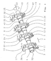
- FIG. 1 the core of a transmission-side switching and selection device 1, to which a preferably only about its longitudinal axis 32 rotatably mounted switching and selector shaft 2 belongs.
- shift finger 3 to 10 are formed, which point away radially from the shift and selector shaft 2 at different circumferential angles.
- the switching and selector shaft 2 passes through a central opening 33 in so-called switching frame 11, 12, 13 and 14, which have an approximately oval circumferential geometry in this embodiment.
- the shift fingers of the shift and selector shaft 2 cooperate with these shift frames 11, 12, 13, 14 in such a way that with the aid of these transmissions gears can be engaged or removed.
- gears are in the present example that of a seven-speed automotive manual transmission, wherein the reverse gear RG and the second gear G2 the gear frame 11, the first gear G1 and the third gear G3 the gear frame 12, the fourth gear G4 and the sixth gear G6 the Shift frame 13 and the fifth gear G5 and the seventh gear G7 are associated with the switching frame 14.
- the neutral position N of the transmission corresponds to a Broauslenkung all switching frame.
- this switching device 1 can be used without major changes for another multi-speed, such as six-speed transmission, in which then only one gear is operated with one of the switching frame.
- a drive device 23 is, for example, an electric stepping motor which can be actuated on the basis of sensor information regarding the presence of a ratio change request by a control device with actuation commands.
- this preferably consists of a formed sheet metal part or a metal casting with the already mentioned central opening 33 through which the switching and selector shaft 2 is feasible.
- a Wellenkegang 15 is formed in the upper region of the opening 33, in which the switching and selector shaft 2 can be accommodated.
- actuating cam which are arranged in pairs as actuating cam 16, 17 and actuating cam 18, 19 in the lower or upper portion of the switching frame 11.
- Fig. 2 clearly shows, a cam pair 18, 19 axially shorter than the other cam pair 16 and 17, so that the arranged on the shift and selector shaft 2 axially in front of the shorter shift finger 4 longer shift finger 3 at a rotation of the shift and selector shaft 2 without problems the cam pair 18, 19 can be moved past.
- cam radial clearance contours 28, 29 are formed, which allow a free pivoting movement.
- the shift and selector shaft 2 is rotated about its longitudinal axis 32 so far that the shift finger 3 on the actuating surface 24 of the cam 17 to the plant and then moves the switch frame 11 to the left.
- the insertion of the seventh gear G7 on the switching frame 14 is effected by applying an operating force of the shift finger 9 on the cam 37, while the same acts to engage the fifth gear G5 on the actuating surface 35 of the cam 40.
- the removal of the fifth gear G5 is carried out by applying an actuating force by the short shift finger 10 on the cam 42 of the switching frame fourteenth
- a rotation of the shift and selector shaft 2 after inserting the seventh gear G7 on the switching frame 14 is limited by a contact of the shift finger 3 on the surface 36 of the cam 17 of the switching frame 11. Accordingly, the surface 38 on the switching frame 14 forms a stop for the Shift finger 9, when the reverse gear RG is connected and the shift and selector shaft 2 should be rotated further.
- the cam 16 is provided on the switching frame 11, on the actuating surface 25 of the shift finger 4 can be applied.
- the second gear G2 is engaged.
- the shift finger 3 then leaves the actuating surface 25 of the cam 16th
- the shift finger 6 presses on the switching frame 12 on the in Fig. 1 by the shift finger 6 concealed Aussteckocken for the first gear G1 so that it is designed. at a further rotation of the shift and selector shaft 2 in the clockwise direction of the shift finger 6 then passes after overcoming the neutral position to the actuating surface of the cam 34, so that the third gear G3 is engaged.
- the operation for engaging the first gear G1 on the shift frame 12 is performed by the shift finger 5 on the same operation surface 39 of the cam 41 as in the layout of the third gear G3.
- the shift finger 3 plunges into the space formed by the pair of cams 16, 17 of the shift frame 11, while the shift finger 5 expands from the gap which is formed between the cam pair associated with it in this shift position.
- the shift finger 3 engages the actuating surface 24 of the cam 17 on the switching frame 11 and begins with the laying out of the second gear G2 and the engagement of the reverse gear RG.
- the first gear G1 remains engaged.
- the switching frame 11 and the associated with this switching frame 11 thrust-train means 20, 21 are substantially reciprocated axially, so that their input and Auslegeschulen on the aforementioned synchronization and Coupling means of the transmission to be transmitted.
- the described interaction of the shift fingers 3, 4 and the shift frame 11 of the shift operation 1 works in the other switching frame 12, 13, 14 and shift fingers as well.
- the positions of the cams of each switching frame and in a comparison of the switching frame 11, 12, 13, 14 are arranged with each other so that at a certain rotation angle of the switching and selector shaft. 2 in each case only one gear can be engaged and / or interpreted.
- the gearshift positions RG, N, G1, G2, G3, G4, G5, G6, G7 are only sequential, so successively selectable.
- FIG. 3 and FIG. 4 illustrate the example of a schematic end view of the switching frame 11, the arrangement of the cams 16 to 19 can be largely arbitrary to the switch frame, but the requirements of the actuation kinematics, such as the number and arrangement of the shift finger on the shift and selector shaft, must be considered.
- Such an arrangement of the insertion cams (by way of example 16, 17) to the deployment cams (by way of example 18, 19) can be implemented such that the spacer center line 31 between the deployment cams 18, 19 in accordance with FIG Fig. 3 above the distance center line 30 and the longitudinal axis 32 of the shift and selector shaft 2, or according to Fig. 4 is positioned below the said longitudinal axis 32 and the spacer center line 30 between the insert cams 16, 17 on the switch frame 11.
- an adjusting device connected to the shift and selector shaft 2 is fast enough to be able to ensure that one or more gears are skipped at a speed that is sufficiently high for the vehicle user.
- a second adjusting device to the switching and selector shaft 2 may be arranged, with the latter according to the directional arrow 22 axially back and forth is displaceable.
- Such an adjusting device may be, for example, a spindle drive driven by an electric motor or an axially acting electromagnet.
- the shift and selector shaft 2 is first rotated so far about its longitudinal axis until the switch frame 14 with respect to the seventh gear G7 is brought into neutral position.
- the shift finger 9 presses against the actuating surface 37 of the cam 37, so that the shift frame 14 is displaced to the left and as a result of the seventh gear G7 is removed.
- the shift and selector shaft 2 is moved axially according to the direction arrow 22 until all shift fingers from the engagement areas of the switching frame 11, 12, 13, 14 are removed.
- the present constructional embodiment of the invention is specially adapted for use in a dual-clutch transmission in which two gears are always switched except for the periods when selecting and switching the transmission.
- the switching device 1 can be adjusted so that in addition to the inserted active gear of the respective upstream or downstream gear can be preselected, whereby this switching device is also suitable for dual-clutch transmission.
Landscapes
- Engineering & Computer Science (AREA)
- General Engineering & Computer Science (AREA)
- Mechanical Engineering (AREA)
- Gear-Shifting Mechanisms (AREA)
- Structure Of Transmissions (AREA)
Claims (17)
- Dispositif de changement de vitesses (1) d'une boîte mécanique à plusieurs rapports, dotée d'un arbre de commande et de sélection (2), sur celui-ci étant disposés des doigts de commande (3 à 10), dotée d'un grand nombre de cadres de commande (11 à 14), dont les orifices (33) sont traversés par l'arbre de commande et de sélection (2), dotée d'au moins un élément de poussée/traction (20, 21) réalisé sur chacun des cadres de commande (11 à 14), ces éléments de poussée/traction étant liés à des moyens d'accouplement, à l'aide desquels des pignons fous de la boîte de vitesses peuvent être liés solidaires en rotation à l'arbre de la boîte de vitesses, sachant qu'une seule rotation de l'arbre de commande et de sélection (2) autour de son axe longitudinal (32) permet de sélectionner et engager chacun des rapports de la boîte de vitesses, caractérisé en ce que à l'aide d'au moins un cadre de commande (11 1 à 14) il est possible d'engager et de désengager deux rapports, et cela alternativement l'un par rapport à l'autre, sachant qu'à ce cadre de commande sont associés deux doigts de commande (3 et 4, 5 et 6, 7 et 8, 9 et 10) disposés sur l'arbre de commande et de sélection et que le cadre de commande comporte des cames (16 à 19, 34, 37, 40, 41, 42), celles-ci déplaçant lors d'une rotation de l'arbre de commande et de sélection (2) et en combinaison avec les doigts de commande (3 à 10) le cadre de commande (11 à 14) transversalement par rapport à l'axe longitudinal (32) de cet arbre de commande et de sélection (2), sachant que sur les cadres de commande (11 à 14) sont réalisés - pour un rapport de boîte de vitesses à engager (G1, G2, G3, G4, G5, G6, G7, RG) - une came d'engagement pour l'engagement du rapport et une came de désengagement pour le désengagement du rapport et sachant qu'aux cames d'engagement (16, 17, 34) et aux cames de désengagement (18, 19, 42) du cadre de commande sont associés des rayons d'action mutuellement distants en sens axial et/ou radial et coïncidant avec les plans de rotation des doigts de commande correspondants.
- Dispositif de changement de vitesses selon la revendication 1, caractérisé en ce que les cames (16, 17, 34; 18, 19; 42) sont alignées essentiellement parallèles à l'axe longitudinal (32) de l'arbre de commande et de sélection (2) au niveau des cadres de commande (11 à 14).
- Dispositif de changement de vitesses selon au moins une des revendications précédentes, caractérisé en ce que les cames (16, 17, 34; 18, 19, 42) des cadres de commande (11 à 14) sont juxtaposés par paires.
- Dispositif de changement de vitesses selon au moins une des revendications précédentes, caractérisé en ce que les cames (16, 17, 34; 18, 19, 42) comportent des surfaces d'actionnement (24, 25, 26, 27, 36, 38, 39) essentiellement orientées l'une par rapport à l'autre et radialement pour l'appui des doigts de commande (3 à 10).
- Dispositif de changement de vitesses selon la revendication 4, caractérisé en ce que les surfaces d'actionnement (24, 25, 26, 27, 36, 38, 39) au niveau des cames (16, 17, 34; 18, 19; 42) sont réalisées de façon à ce qu'elles ne perturbent pas la mobilité d'un doigt de commande engagé (3 à 10) du même cadre de commande (11 à 14).
- Dispositif de changement de vitesses selon au moins une des revendications précédentes, caractérisé en ce que sur le même cadre de commande (11 bis 14) la distance entre les cames (18, 19) de la paire de cames de désengagement est différente de la distance des cames (16, 17) de la paire de cames d'engagement.
- Dispositif de changement de vitesses selon au moins une des revendications précédentes, caractérisé en ce que sur le même cadre de commande (11 à 14) la ligne médiane de distance (31) entre deux cames de désengagement (18, 19) est orientée symétriquement ou latéralement décalée par rapport à la ligne médiane de distance (30) entre deux cames d'engagement (16, 17).
- Dispositif de changement de vitesses selon au moins une des revendications précédentes, caractérisé en ce que les moyens de poussée/traction (20, 21) disposés sur les cadres de commande (11 à 14) sont réalisés en tant que tiges ou pièces en tôle estampées.
- Dispositif de changement de vitesses selon au moins une des revendications précédentes, caractérisé en ce que les rapports de la boîte de vitesses (RG, G1, G2, G3, G4, G5, G6, G7) peuvent être sélectionnés et engagés de façon séquentielle.
- Dispositif de changement de vitesses selon au moins une des revendications précédentes, caractérisé en ce que l'arbre de commande et de sélection (2) peut être tourné autour de son axe longitudinal (32) à l'aide d'un actionneur (23).
- Dispositif de changement de vitesses selon au moins une des revendications précédentes, caractérisé en ce que l'arbre de commande et de sélection (2) peut être déplaçé axialement à l'aide d'un dispositif d'entraînement (22), et cela de façon à ce que les doigts de commande (3 à 10) peuvent être déplaçés hors d'une position d'engagement ou vers une position d'engagement par rapport aux cames (16, 17, 34; 18, 19; 42).
- Dispositif de changement de vitesses selon au moins une des revendications précédentes, caractérisé en ce que par rotation de l'arbre de commande et de sélection (2) de moins de 360°, de préférence de moins de 270°, il est possible d'atteindre toutes les positions de commande de la boîte de vitesses et d'engager et de désengager les rapports y associés (RG, G1, G2, G3, G4. G5, G6, G7).
- Dispositif de changement de vitesses selon au moins une des revendications précédentes, caractérisé en ce que l'arbre de commande et de sélection (2) peut être déplaçé constamment ou partiellement en sens axial en fonction de son angle de rotation et de son sens de rotation, et cela de façon à ce que un ou plusieurs doigts de commande (3 à 10) peuvent être amenés en position d'actionnement de plus d'un cadre de commande (11 à 14).
- Dispositif de changement de vitesses selon au moins une des revendications précédentes, caractérisé en ce que l'arbre de commande et de sélection (2) est composé de plusieurs parties.
- Dispositif de changement de vitesses selon la revendication 14, caractérisé en ce que les demi-arbres de l'arbre de l'arbre de commande et de sélection (2) sont disposés et logés parallèles à l'axe, axialement l'un derrière l'autre ou coaxialement l'un par rapport à l'autre.
- Dispositif de changement de vitesses selon la revendication 14 ou 15, caractérisé en ce que sur les cadres de commande est disposé un dispositif de verrouillage, à l'aide duquel il est possible d'éviter l'engagement simultané de deux rapports de la boîte de vitesses sur un arbre à trains d'engrenages d'une transmission à double embrayage.
- Dispositif de changement de vitesses selon au moins une des revendications précédentes, caractérisé en ce que sur les cadres de commande est disposé un dispositif de verrouillage, à l'aide duquel il est possible d'éviter l'engagement simultané de deux rapports de la boîte de vitesses sur un arbre à trains d'engrenages d'une transmission à double embrayage.
Applications Claiming Priority (2)
| Application Number | Priority Date | Filing Date | Title |
|---|---|---|---|
| DE102004001741A DE102004001741A1 (de) | 2004-01-13 | 2004-01-13 | Schaltvorrichtung an einem mehrgängigen Schaltgetriebe |
| PCT/EP2004/014654 WO2005068880A1 (fr) | 2004-01-13 | 2004-12-23 | Dispositif de commutation dans une boite de vitesses a vitesses multiples |
Publications (2)
| Publication Number | Publication Date |
|---|---|
| EP1704351A1 EP1704351A1 (fr) | 2006-09-27 |
| EP1704351B1 true EP1704351B1 (fr) | 2009-02-04 |
Family
ID=34744691
Family Applications (1)
| Application Number | Title | Priority Date | Filing Date |
|---|---|---|---|
| EP04804248A Expired - Lifetime EP1704351B1 (fr) | 2004-01-13 | 2004-12-23 | Dispositif de commutation dans une boite de vitesses a vitesses multiples |
Country Status (4)
| Country | Link |
|---|---|
| EP (1) | EP1704351B1 (fr) |
| AT (1) | ATE422230T1 (fr) |
| DE (2) | DE102004001741A1 (fr) |
| WO (1) | WO2005068880A1 (fr) |
Families Citing this family (1)
| Publication number | Priority date | Publication date | Assignee | Title |
|---|---|---|---|---|
| DE102008036173B3 (de) * | 2008-08-02 | 2009-09-24 | Fsg Automotive Holding Ag | Schaltrahmen |
Family Cites Families (8)
| Publication number | Priority date | Publication date | Assignee | Title |
|---|---|---|---|---|
| US1889909A (en) * | 1930-08-23 | 1932-12-06 | Roy M Upton | Reverse gear and clutch operating mechanism |
| DE585837C (de) * | 1930-11-13 | 1933-10-11 | Eduard Janik | Schaltvorrichtung fuer Zahnraederwechselgetriebe von Kraftfahrzeugen |
| US2485151A (en) * | 1945-11-24 | 1949-10-18 | Gorrell John Ellison | Gear-changing drive |
| DE1480495A1 (de) * | 1965-10-22 | 1969-10-30 | Wtz Automobilbau Hohenstein Er | Vorrichtung zum Schalten von Verteilergetrieben und zum Betaetigen der Ausgleichsgetriebesperre in Kraftfahrzeugen mit Allradantrieb |
| DE1650633A1 (de) * | 1967-08-11 | 1970-01-08 | Bosch Gmbh Robert | Gangschalteinrichtung fuer ein mechanisches Getriebe |
| US3893347A (en) * | 1973-06-25 | 1975-07-08 | Massey Ferguson Services Nv | Change speed transmissions and controls therefor |
| US4335623A (en) * | 1980-03-07 | 1982-06-22 | Mack Trucks, Inc. | Transmission shift control mechanism |
| DE10253471A1 (de) * | 2002-11-16 | 2004-08-26 | Zf Friedrichshafen Ag | Schaltvorrichtung für ein Getriebe |
-
2004
- 2004-01-13 DE DE102004001741A patent/DE102004001741A1/de not_active Withdrawn
- 2004-12-23 AT AT04804248T patent/ATE422230T1/de not_active IP Right Cessation
- 2004-12-23 WO PCT/EP2004/014654 patent/WO2005068880A1/fr not_active Ceased
- 2004-12-23 EP EP04804248A patent/EP1704351B1/fr not_active Expired - Lifetime
- 2004-12-23 DE DE502004008955T patent/DE502004008955D1/de not_active Expired - Lifetime
Also Published As
| Publication number | Publication date |
|---|---|
| DE102004001741A1 (de) | 2005-08-11 |
| ATE422230T1 (de) | 2009-02-15 |
| DE502004008955D1 (de) | 2009-03-19 |
| WO2005068880A1 (fr) | 2005-07-28 |
| EP1704351A1 (fr) | 2006-09-27 |
Similar Documents
| Publication | Publication Date | Title |
|---|---|---|
| EP1561055B1 (fr) | Dispositif de changement de vitesse pour boite de vitesses | |
| DE19924335B4 (de) | Stellvorrichtung und Stufengetriebe mit Stellvorrichtung für ein Kraftfahrzeug | |
| DE19543645B4 (de) | Vorrichtung zum Schalten von sperrsynchronisierten Fahrzeuggetrieben | |
| DE102008048889B4 (de) | Gangwechselsteuersystem eines Automatikgetriebes | |
| EP2496860B1 (fr) | Boîte de vitesses à plusieurs groupes | |
| EP2918877B1 (fr) | Agencement de commutation pour une boîte de vitesses de véhicule automobile et procédé de commutation | |
| DE19702541B4 (de) | Zweiteiliges Gangrad für Schaltgetriebe | |
| EP1556637B1 (fr) | Mecanismes de changement de vitesse | |
| WO2018055041A2 (fr) | Actionneur de rapport et de voie (xy) de boîte de vitesses | |
| WO2014146771A1 (fr) | Dispositif d'actionnement pour une boîte de vitesses d'un véhicule automobile et boîte de vitesses correspondante d'un véhicule automobile | |
| EP1333200B1 (fr) | Dispositif de changement de vitesses pour transmission à engrenages droits | |
| DE102004006807A1 (de) | Betätigungsvorrichtung zur Realisierung der Schaltung des Getriebes eines Kraftfahrzeuges, vorzugsweise der Schaltungen eines Doppelkupplungsgetriebes | |
| EP1714057B1 (fr) | Dispositif de commutation a une seule tringle sur une boite de vitesses | |
| EP2179200B1 (fr) | Dispositif de passage des vitesses pour une boîte de vitesses d'un véhicule motorisé comportant un dispositif de verrouillage | |
| DE102014115373B4 (de) | Schaltanordnung für ein Kraftfahrzeuggetriebe und Schaltverfahren | |
| DE102014115371B4 (de) | Schaltanordnung für ein Kraftfahrzeuggetriebe und Schaltverfahren | |
| DE102012214430A1 (de) | Schalteinrichtung für ein Schaltgetriebe | |
| EP1704351B1 (fr) | Dispositif de commutation dans une boite de vitesses a vitesses multiples | |
| DE102006061607A1 (de) | Schaltvorrichtung eines manuell schaltbaren KFZ-Getriebes | |
| EP1442241B1 (fr) | Procede permettant le changement de vitesses dans une boite de vitesses manuelle a plusieurs rapports, et boite de vitesses manuelle a plusieurs rapports comprenant une tringlerie de transmission | |
| DE60006457T2 (de) | Getriebe kompakter Bauart mit Schwenkfüssen zur Betätigung von Schaltgabeln | |
| EP1310707B1 (fr) | Dispositif de changement de vitesses et méthode de mouvement et guidage de fourchettes dans une transmission à changement de vitesses | |
| DE102005058406B4 (de) | Betätigungseinrichtung für ein Schaltgetriebe | |
| DE10332494A1 (de) | Stelleinrichtung zur Betätigung, insbesondere automatisierten Betätigung eines Schaltgetriebes | |
| DE102004041353A1 (de) | Schaltvorrichtung für ein Gangwechselgetriebe, vzw. für ein Doppelkupplungsgetriebe |
Legal Events
| Date | Code | Title | Description |
|---|---|---|---|
| PUAI | Public reference made under article 153(3) epc to a published international application that has entered the european phase |
Free format text: ORIGINAL CODE: 0009012 |
|
| 17P | Request for examination filed |
Effective date: 20060613 |
|
| AK | Designated contracting states |
Kind code of ref document: A1 Designated state(s): AT BE BG CH CY CZ DE DK EE ES FI FR GB GR HU IE IS IT LI LT LU MC NL PL PT RO SE SI SK TR |
|
| 17Q | First examination report despatched |
Effective date: 20061123 |
|
| DAX | Request for extension of the european patent (deleted) | ||
| GRAP | Despatch of communication of intention to grant a patent |
Free format text: ORIGINAL CODE: EPIDOSNIGR1 |
|
| GRAS | Grant fee paid |
Free format text: ORIGINAL CODE: EPIDOSNIGR3 |
|
| GRAA | (expected) grant |
Free format text: ORIGINAL CODE: 0009210 |
|
| AK | Designated contracting states |
Kind code of ref document: B1 Designated state(s): AT BE BG CH CY CZ DE DK EE ES FI FR GB GR HU IE IS IT LI LT LU MC NL PL PT RO SE SI SK TR |
|
| REG | Reference to a national code |
Ref country code: GB Ref legal event code: FG4D Free format text: NOT ENGLISH |
|
| REG | Reference to a national code |
Ref country code: CH Ref legal event code: EP |
|
| REG | Reference to a national code |
Ref country code: IE Ref legal event code: FG4D Free format text: LANGUAGE OF EP DOCUMENT: GERMAN |
|
| REF | Corresponds to: |
Ref document number: 502004008955 Country of ref document: DE Date of ref document: 20090319 Kind code of ref document: P |
|
| NLV1 | Nl: lapsed or annulled due to failure to fulfill the requirements of art. 29p and 29m of the patents act | ||
| PG25 | Lapsed in a contracting state [announced via postgrant information from national office to epo] |
Ref country code: LT Free format text: LAPSE BECAUSE OF FAILURE TO SUBMIT A TRANSLATION OF THE DESCRIPTION OR TO PAY THE FEE WITHIN THE PRESCRIBED TIME-LIMIT Effective date: 20090204 Ref country code: NL Free format text: LAPSE BECAUSE OF FAILURE TO SUBMIT A TRANSLATION OF THE DESCRIPTION OR TO PAY THE FEE WITHIN THE PRESCRIBED TIME-LIMIT Effective date: 20090204 Ref country code: ES Free format text: LAPSE BECAUSE OF FAILURE TO SUBMIT A TRANSLATION OF THE DESCRIPTION OR TO PAY THE FEE WITHIN THE PRESCRIBED TIME-LIMIT Effective date: 20090515 Ref country code: FI Free format text: LAPSE BECAUSE OF FAILURE TO SUBMIT A TRANSLATION OF THE DESCRIPTION OR TO PAY THE FEE WITHIN THE PRESCRIBED TIME-LIMIT Effective date: 20090204 Ref country code: SI Free format text: LAPSE BECAUSE OF FAILURE TO SUBMIT A TRANSLATION OF THE DESCRIPTION OR TO PAY THE FEE WITHIN THE PRESCRIBED TIME-LIMIT Effective date: 20090204 |
|
| PG25 | Lapsed in a contracting state [announced via postgrant information from national office to epo] |
Ref country code: SE Free format text: LAPSE BECAUSE OF FAILURE TO SUBMIT A TRANSLATION OF THE DESCRIPTION OR TO PAY THE FEE WITHIN THE PRESCRIBED TIME-LIMIT Effective date: 20090504 Ref country code: PL Free format text: LAPSE BECAUSE OF FAILURE TO SUBMIT A TRANSLATION OF THE DESCRIPTION OR TO PAY THE FEE WITHIN THE PRESCRIBED TIME-LIMIT Effective date: 20090204 Ref country code: IS Free format text: LAPSE BECAUSE OF FAILURE TO SUBMIT A TRANSLATION OF THE DESCRIPTION OR TO PAY THE FEE WITHIN THE PRESCRIBED TIME-LIMIT Effective date: 20090604 |
|
| REG | Reference to a national code |
Ref country code: IE Ref legal event code: FD4D |
|
| PG25 | Lapsed in a contracting state [announced via postgrant information from national office to epo] |
Ref country code: EE Free format text: LAPSE BECAUSE OF FAILURE TO SUBMIT A TRANSLATION OF THE DESCRIPTION OR TO PAY THE FEE WITHIN THE PRESCRIBED TIME-LIMIT Effective date: 20090204 Ref country code: PT Free format text: LAPSE BECAUSE OF FAILURE TO SUBMIT A TRANSLATION OF THE DESCRIPTION OR TO PAY THE FEE WITHIN THE PRESCRIBED TIME-LIMIT Effective date: 20090706 Ref country code: IE Free format text: LAPSE BECAUSE OF FAILURE TO SUBMIT A TRANSLATION OF THE DESCRIPTION OR TO PAY THE FEE WITHIN THE PRESCRIBED TIME-LIMIT Effective date: 20090204 Ref country code: DK Free format text: LAPSE BECAUSE OF FAILURE TO SUBMIT A TRANSLATION OF THE DESCRIPTION OR TO PAY THE FEE WITHIN THE PRESCRIBED TIME-LIMIT Effective date: 20090204 Ref country code: CZ Free format text: LAPSE BECAUSE OF FAILURE TO SUBMIT A TRANSLATION OF THE DESCRIPTION OR TO PAY THE FEE WITHIN THE PRESCRIBED TIME-LIMIT Effective date: 20090204 |
|
| PG25 | Lapsed in a contracting state [announced via postgrant information from national office to epo] |
Ref country code: RO Free format text: LAPSE BECAUSE OF FAILURE TO SUBMIT A TRANSLATION OF THE DESCRIPTION OR TO PAY THE FEE WITHIN THE PRESCRIBED TIME-LIMIT Effective date: 20090204 Ref country code: SK Free format text: LAPSE BECAUSE OF FAILURE TO SUBMIT A TRANSLATION OF THE DESCRIPTION OR TO PAY THE FEE WITHIN THE PRESCRIBED TIME-LIMIT Effective date: 20090204 |
|
| PLBE | No opposition filed within time limit |
Free format text: ORIGINAL CODE: 0009261 |
|
| STAA | Information on the status of an ep patent application or granted ep patent |
Free format text: STATUS: NO OPPOSITION FILED WITHIN TIME LIMIT |
|
| 26N | No opposition filed |
Effective date: 20091105 |
|
| PG25 | Lapsed in a contracting state [announced via postgrant information from national office to epo] |
Ref country code: BG Free format text: LAPSE BECAUSE OF FAILURE TO SUBMIT A TRANSLATION OF THE DESCRIPTION OR TO PAY THE FEE WITHIN THE PRESCRIBED TIME-LIMIT Effective date: 20090504 |
|
| BERE | Be: lapsed |
Owner name: ZF FRIEDRICHSHAFEN A.G. Effective date: 20091231 |
|
| PG25 | Lapsed in a contracting state [announced via postgrant information from national office to epo] |
Ref country code: MC Free format text: LAPSE BECAUSE OF NON-PAYMENT OF DUE FEES Effective date: 20100701 |
|
| REG | Reference to a national code |
Ref country code: CH Ref legal event code: PL |
|
| GBPC | Gb: european patent ceased through non-payment of renewal fee |
Effective date: 20091223 |
|
| REG | Reference to a national code |
Ref country code: FR Ref legal event code: ST Effective date: 20100831 |
|
| PG25 | Lapsed in a contracting state [announced via postgrant information from national office to epo] |
Ref country code: BE Free format text: LAPSE BECAUSE OF NON-PAYMENT OF DUE FEES Effective date: 20091231 Ref country code: CH Free format text: LAPSE BECAUSE OF NON-PAYMENT OF DUE FEES Effective date: 20091231 Ref country code: FR Free format text: LAPSE BECAUSE OF NON-PAYMENT OF DUE FEES Effective date: 20091231 Ref country code: GR Free format text: LAPSE BECAUSE OF FAILURE TO SUBMIT A TRANSLATION OF THE DESCRIPTION OR TO PAY THE FEE WITHIN THE PRESCRIBED TIME-LIMIT Effective date: 20090505 Ref country code: LI Free format text: LAPSE BECAUSE OF NON-PAYMENT OF DUE FEES Effective date: 20091231 |
|
| PG25 | Lapsed in a contracting state [announced via postgrant information from national office to epo] |
Ref country code: GB Free format text: LAPSE BECAUSE OF NON-PAYMENT OF DUE FEES Effective date: 20091223 |
|
| PG25 | Lapsed in a contracting state [announced via postgrant information from national office to epo] |
Ref country code: IT Free format text: LAPSE BECAUSE OF FAILURE TO SUBMIT A TRANSLATION OF THE DESCRIPTION OR TO PAY THE FEE WITHIN THE PRESCRIBED TIME-LIMIT Effective date: 20090204 |
|
| PG25 | Lapsed in a contracting state [announced via postgrant information from national office to epo] |
Ref country code: LU Free format text: LAPSE BECAUSE OF NON-PAYMENT OF DUE FEES Effective date: 20091223 |
|
| PG25 | Lapsed in a contracting state [announced via postgrant information from national office to epo] |
Ref country code: AT Free format text: LAPSE BECAUSE OF NON-PAYMENT OF DUE FEES Effective date: 20091223 |
|
| PG25 | Lapsed in a contracting state [announced via postgrant information from national office to epo] |
Ref country code: HU Free format text: LAPSE BECAUSE OF FAILURE TO SUBMIT A TRANSLATION OF THE DESCRIPTION OR TO PAY THE FEE WITHIN THE PRESCRIBED TIME-LIMIT Effective date: 20090805 |
|
| PG25 | Lapsed in a contracting state [announced via postgrant information from national office to epo] |
Ref country code: TR Free format text: LAPSE BECAUSE OF FAILURE TO SUBMIT A TRANSLATION OF THE DESCRIPTION OR TO PAY THE FEE WITHIN THE PRESCRIBED TIME-LIMIT Effective date: 20090204 |
|
| PG25 | Lapsed in a contracting state [announced via postgrant information from national office to epo] |
Ref country code: CY Free format text: LAPSE BECAUSE OF FAILURE TO SUBMIT A TRANSLATION OF THE DESCRIPTION OR TO PAY THE FEE WITHIN THE PRESCRIBED TIME-LIMIT Effective date: 20090204 |
|
| PGFP | Annual fee paid to national office [announced via postgrant information from national office to epo] |
Ref country code: DE Payment date: 20131218 Year of fee payment: 10 |
|
| REG | Reference to a national code |
Ref country code: DE Ref legal event code: R119 Ref document number: 502004008955 Country of ref document: DE |
|
| PG25 | Lapsed in a contracting state [announced via postgrant information from national office to epo] |
Ref country code: DE Free format text: LAPSE BECAUSE OF NON-PAYMENT OF DUE FEES Effective date: 20150701 |