EP1704829A1 - Set de butées pour un implant dentaire - Google Patents
Set de butées pour un implant dentaire Download PDFInfo
- Publication number
- EP1704829A1 EP1704829A1 EP05006115A EP05006115A EP1704829A1 EP 1704829 A1 EP1704829 A1 EP 1704829A1 EP 05006115 A EP05006115 A EP 05006115A EP 05006115 A EP05006115 A EP 05006115A EP 1704829 A1 EP1704829 A1 EP 1704829A1
- Authority
- EP
- European Patent Office
- Prior art keywords
- abutment
- cap
- post
- dental
- receiving
- Prior art date
- Legal status (The legal status is an assumption and is not a legal conclusion. Google has not performed a legal analysis and makes no representation as to the accuracy of the status listed.)
- Granted
Links
- 239000004053 dental implant Substances 0.000 title claims abstract description 27
- 239000000463 material Substances 0.000 claims abstract description 18
- 238000000034 method Methods 0.000 claims abstract description 16
- 238000003754 machining Methods 0.000 claims abstract description 14
- 238000004519 manufacturing process Methods 0.000 claims abstract description 9
- 239000007943 implant Substances 0.000 claims description 24
- 239000000853 adhesive Substances 0.000 claims description 6
- 230000001070 adhesive effect Effects 0.000 claims description 6
- 239000000919 ceramic Substances 0.000 claims description 4
- 229910010293 ceramic material Inorganic materials 0.000 claims description 3
- 238000005520 cutting process Methods 0.000 claims description 3
- 238000000227 grinding Methods 0.000 claims description 3
- TWNQGVIAIRXVLR-UHFFFAOYSA-N oxo(oxoalumanyloxy)alumane Chemical compound O=[Al]O[Al]=O TWNQGVIAIRXVLR-UHFFFAOYSA-N 0.000 claims description 3
- RVTZCBVAJQQJTK-UHFFFAOYSA-N oxygen(2-);zirconium(4+) Chemical compound [O-2].[O-2].[Zr+4] RVTZCBVAJQQJTK-UHFFFAOYSA-N 0.000 claims description 3
- 229910001928 zirconium oxide Inorganic materials 0.000 claims description 3
- 238000010276 construction Methods 0.000 description 14
- 238000009966 trimming Methods 0.000 description 5
- PCHJSUWPFVWCPO-UHFFFAOYSA-N gold Chemical compound [Au] PCHJSUWPFVWCPO-UHFFFAOYSA-N 0.000 description 4
- 239000010931 gold Substances 0.000 description 4
- 230000014759 maintenance of location Effects 0.000 description 4
- 229910052751 metal Inorganic materials 0.000 description 4
- 239000002184 metal Substances 0.000 description 4
- 230000007774 longterm Effects 0.000 description 3
- 241001465754 Metazoa Species 0.000 description 2
- 229910001069 Ti alloy Inorganic materials 0.000 description 2
- 238000004026 adhesive bonding Methods 0.000 description 2
- 229910045601 alloy Inorganic materials 0.000 description 2
- 239000000956 alloy Substances 0.000 description 2
- 238000004873 anchoring Methods 0.000 description 2
- 238000005422 blasting Methods 0.000 description 2
- 210000000988 bone and bone Anatomy 0.000 description 2
- 238000005266 casting Methods 0.000 description 2
- 238000004140 cleaning Methods 0.000 description 2
- 230000000694 effects Effects 0.000 description 2
- 229910052737 gold Inorganic materials 0.000 description 2
- 238000003780 insertion Methods 0.000 description 2
- 230000037431 insertion Effects 0.000 description 2
- 229910001092 metal group alloy Inorganic materials 0.000 description 2
- 238000003801 milling Methods 0.000 description 2
- 230000003287 optical effect Effects 0.000 description 2
- 238000002360 preparation method Methods 0.000 description 2
- 229910001258 titanium gold Inorganic materials 0.000 description 2
- 241000894006 Bacteria Species 0.000 description 1
- 241000251131 Sphyrna Species 0.000 description 1
- 238000010521 absorption reaction Methods 0.000 description 1
- 210000003484 anatomy Anatomy 0.000 description 1
- 238000007796 conventional method Methods 0.000 description 1
- 238000011161 development Methods 0.000 description 1
- 238000010304 firing Methods 0.000 description 1
- 238000005304 joining Methods 0.000 description 1
- 239000000203 mixture Substances 0.000 description 1
- 238000012546 transfer Methods 0.000 description 1
Images


Classifications
-
- A—HUMAN NECESSITIES
- A61—MEDICAL OR VETERINARY SCIENCE; HYGIENE
- A61C—DENTISTRY; APPARATUS OR METHODS FOR ORAL OR DENTAL HYGIENE
- A61C8/00—Means to be fixed to the jaw-bone for consolidating natural teeth or for fixing dental prostheses thereon; Dental implants; Implanting tools
- A61C8/0048—Connecting the upper structure to the implant, e.g. bridging bars
-
- A—HUMAN NECESSITIES
- A61—MEDICAL OR VETERINARY SCIENCE; HYGIENE
- A61C—DENTISTRY; APPARATUS OR METHODS FOR ORAL OR DENTAL HYGIENE
- A61C8/00—Means to be fixed to the jaw-bone for consolidating natural teeth or for fixing dental prostheses thereon; Dental implants; Implanting tools
- A61C8/0001—Impression means for implants, e.g. impression coping
-
- A—HUMAN NECESSITIES
- A61—MEDICAL OR VETERINARY SCIENCE; HYGIENE
- A61C—DENTISTRY; APPARATUS OR METHODS FOR ORAL OR DENTAL HYGIENE
- A61C8/00—Means to be fixed to the jaw-bone for consolidating natural teeth or for fixing dental prostheses thereon; Dental implants; Implanting tools
- A61C8/0048—Connecting the upper structure to the implant, e.g. bridging bars
- A61C8/005—Connecting devices for joining an upper structure with an implant member, e.g. spacers
- A61C8/0066—Connecting devices for joining an upper structure with an implant member, e.g. spacers with positioning means
-
- A—HUMAN NECESSITIES
- A61—MEDICAL OR VETERINARY SCIENCE; HYGIENE
- A61C—DENTISTRY; APPARATUS OR METHODS FOR ORAL OR DENTAL HYGIENE
- A61C8/00—Means to be fixed to the jaw-bone for consolidating natural teeth or for fixing dental prostheses thereon; Dental implants; Implanting tools
- A61C8/0048—Connecting the upper structure to the implant, e.g. bridging bars
- A61C8/0077—Connecting the upper structure to the implant, e.g. bridging bars with shape following the gingival surface or the bone surface
-
- A—HUMAN NECESSITIES
- A61—MEDICAL OR VETERINARY SCIENCE; HYGIENE
- A61C—DENTISTRY; APPARATUS OR METHODS FOR ORAL OR DENTAL HYGIENE
- A61C8/00—Means to be fixed to the jaw-bone for consolidating natural teeth or for fixing dental prostheses thereon; Dental implants; Implanting tools
- A61C8/0048—Connecting the upper structure to the implant, e.g. bridging bars
- A61C8/005—Connecting devices for joining an upper structure with an implant member, e.g. spacers
- A61C8/006—Connecting devices for joining an upper structure with an implant member, e.g. spacers with polygonal positional means, e.g. hexagonal or octagonal
-
- A—HUMAN NECESSITIES
- A61—MEDICAL OR VETERINARY SCIENCE; HYGIENE
- A61C—DENTISTRY; APPARATUS OR METHODS FOR ORAL OR DENTAL HYGIENE
- A61C8/00—Means to be fixed to the jaw-bone for consolidating natural teeth or for fixing dental prostheses thereon; Dental implants; Implanting tools
- A61C8/0048—Connecting the upper structure to the implant, e.g. bridging bars
- A61C8/005—Connecting devices for joining an upper structure with an implant member, e.g. spacers
- A61C8/0069—Connecting devices for joining an upper structure with an implant member, e.g. spacers tapered or conical connection
Definitions
- the invention relates to an implant-supported dental prosthesis, particularly an abutment set for a dental implant and a method for manufacturing a dental prosthesis.
- Enossal implants are increasingly employed for anchoring dental prostheses.
- the use of conical posts which are inserted with a conical section in a positive-locking and frictional manner into a corresponding conical hole of the implant and are secured by means of a central screw, as known for instance from EP 0 707 835 A1 has the advantage over other geometrically interlocked types of connection that a high position stability under load is ensured and a rotational alignment in any desired position is possible.
- the latter is particularly advantageous in the case of construction posts on which the occlusal construction peg provided for connection with the dental prosthesis is angled.
- the conical connection between the enossal implant and the construction post is free from gaps and bacteria-tight.
- connection based on a cone is known from US 4,772,204 A corresponding to WO 85/02337 and US 5,674,072 corresponding to EP 0 707 835 A1 .
- Anatomical, biomechanical and aesthetic aspects particularly for single tooth dental prostheses typically require the use of a mechanical connection between the implant components omitting any rotation or move between the components.
- a mechanical connection having an angle between the part anchored in the bone and the part carrying the dental structure which projects into the mouth cavity due to the individual conditions of teeth arrangement in the mouth of the patient
- esthetical and functional performance typically require exact rotational positioning of the components to each other even where the axis of the components are aligned to each other.
- the conical crown technique is a proven method.
- an occlusal conical peg is provided on each abutment post, serving as the force-transmitting connection with the dental prosthesis.
- an impression is usually taken, by which the position of all the conical pegs is determined.
- the dental technician produces an analogous model from this impression in the laboratory.
- the dental technician models a primary crown in wax on the conical peg and pre-mills it in the corresponding conical angle with the aid of a milling unit.
- the primary crown is then pegged and embedded; it is cast, removed from the embedding material, blasted and fitted.
- the primary crown is after-milled and polished.
- a secondary crown is produced on the primary crown with modelling plastic and wax, in particular as a facing bridge, as caps without retention for gluing in a metal frame or as a cap with retention for incorporating into prostheses.
- the secondary crown is pegged and embedded; it is cast, removed from the embedding material, blasted and fitted.
- the use of embedded conical caps as connecting elements between the conical pegs of the construction posts and the dental prosthesis enables the dental prosthesis to be completed in a single session with prefabricated components and in particular without taking impressions and producing models beforehand, by joining the conical caps in their position located on the conical pegs with the main body of the prosthesis by conventional techniques, in particular by gluing or polymerizing-in.
- the need to model a primary crown on the conical peg of the construction post and to produce and work it is eliminated.
- any need to carry out any further work in the dental laboratory after production of the actual dental prosthesis and fitting in the dental practice is eliminated. Any taking of impressions and production of models is eliminated.
- Optimum alignment of the conical peg is achieved by the free positioning of straight and angled construction posts in the conical hole of the implant.
- Retention projections which allow an increased anchoring of the conical caps in the main body of the dental prosthesis are preferably provided on the outside of the conical caps. These can be, for example, circumferential bulges.
- the process suggested by this prior art comprises the use of prefabricated conical caps as connecting elements, wherein the main body of the dental prosthesis, in the region in each case of a construction peg, has a basal recess which has a lateral filling opening provided, in that on each conical peg of the construction posts in each case a conical cap which matches this is mounted, in that the dental prosthesis is inserted into the mouth such that each conical cap projects into a basal recess, and in that each basal recess is filled with self-curing plastic through the lateral filling opening, and after curing thereof the dental prosthesis is removed and finished.
- the prepared dental prosthesis is therefore inserted and completed in a single session in the dental practice exclusively using prefabricated components, without further working steps in the dental laboratory being necessary.
- the patient can therefore leave the dental practice with the completed dental prosthesis directly after insertion of the dental prosthesis.
- the implant supported dental prosthesis and process suggested is generally directed to the mechanical fixing of a multi-teeth prosthesis on a multiplicity of dental implants, like a bridge prosthesis, that is, each single implant abutment arrangement must not require a specific rotational relation to the bridge implant, as the rotational fixing of the implant is performed by the multiplicity of fixing joints.
- the prefabricated components of the implant supported dental prosthesis and process suggested are produced and selected for size fitting purposes only.
- a large step forward to an inexpensive high quality single tooth prosthesis can be achieved by providing an anatomically pre-configured abutment set for a dental implant prefabricated such that today's typical trimming for individualization of the abutment by the dental laboratory can be omitted.
- an abutment set for a dental implant comprising an abutment post for fixing to a dental implant, which abutment post is anatomically pre-configured, and an abutment cap, which cap is an anatomically pre-configured and adapted for mounting onto said abutment post without further machining by the customer, wherein the abutment post is adapted for fixing to a dental implant and for receiving said abutment cap without further machining by the customer, and the abutment cap is adapted to receiving a veneering, and the abutment cap and the abutment post being pre-fabricated for providing appropriate dental prostheses for a multiplicity of different patients.
- the abutment set according to the invention reduces the workload for the dental laboratory when preparing state of the art dental prosthesis, focusing the work of the dental laboratory to the modeling and fixing of the veneering.
- the over all costs for obtaining a dental prosthesis can be significantly reduced and the quality standard of a dental implant can be improved.
- the means for defined rotational and lateral fixing in impression material applied by a dentist has at least one protrusion, located generally opposite to the connecting portion of the cap for cementing onto the abutment post, the protrusion being totally or partially removable by cutting, grinding or breaking prior to receiving the veneering.
- the customer may optimize the mechanical support of the veneering and the optical properties of the dental prosthesis.
- the abutment cap and the abutment post having functional surface elements for providing a predetermined rotational orientation relative to each other.
- the abutment cap is characterized in that the anatomically pre-configuration of the cap comprises a bottom rim section surrounding the connecting portion, the shape of the rim section being adapted to the natural gingival contour, whilst the prior art generally prefers rotational symmetry of the bottom rim section of a cap to ease handling and storing of impression and construction caps.
- the embodiment according to the invention provides best esthetical results for the dental prosthesis as the prosthesis fits in the gingival situation of the patient's mouth like a natural tooth, and avoids that the dental implant can be seen from outside. On the other hand this is achieved without a need for trimming by the dental laboratory when preparing the prosthesis, thus further reducing the costs for the prosthesis while improving the quality of the result at the same time.
- the abutment set according to the invention is characterized in that the abutment post and/or the abutment cap is made of ceramics, preferably a ceramic material comprising zirconium oxide and/or aluminum oxide.
- the abutment post and/or the abutment cap is made of ceramics, preferably a ceramic material comprising zirconium oxide and/or aluminum oxide.
- the abutment post has a portion for receiving the abutment cap, wherein the surface of said portion having a preconditioned surface generally ready for receiving cementum or adhesive for mechanical fixing of the abutment cap. This allows to reduce preparation work like blasting to what is needed for cleaning the post as required.
- the abutment cap has a connecting portion for cementing onto the abutment post, wherein the surface of said connecting portion is a preconditioned surface generally ready for receiving cementum or adhesive for rigid mechanical fixing to the abutment post.
- the abutment cap has a receiving portion for receiving the veneering, wherein the said receiving portion has a preconditioned surface generally ready for receiving the veneering in a rigid mechanical fixing configuration.
- a dental prosthesis comprising an abutment post and an abutment cap according to what is described above.
- a method for manufacturing a dental prosthesis for mounting on a dental implant comprising the steps of selecting a set of pre-fabricated abutment post and abutment cap, obtaining an impression of the abutment post and abutment cap removably fixed to said implant within the dental arrangement inside the mouth of the patient, and adding a veneering to the abutment cap, without further machining of the abutment cap and the abutment post for mounting said abutment cap to said abutment post.
- the selection step is selecting an abutment post and an abutment cap according to what is described above.
- the method according to the invention further includes the step of removing the abutment cap from the impression, partially or totally removing a protrusion for rotational and lateral fixing of the abutment cap to the impression, if any, prior to adding the veneering to the abutment cap.
- the method according to the invention further comprises the step of mounting the abutment post to the dental implant and cementing the abutment cap carrying the veneering to the abutment post.
- the invention may be put into effect most effectively by treating a human or animal being with a dental prosthesis as described above.
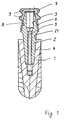
- Fig. 1 shows a general arrangement of a dental implant 1, and an abutment set comprising an abutment post 2 and a cap 7 mounted thereon.
- the enossal dental implant 1 is intended to be screwed into a prepared threaded hole in a jaw bone (not shown).
- a construction or abutment post 2 for instance with a conical peg 21 on the implant side, is inserted into a corresponding conical hole 4 of the implant 1 and secured by means of a central screw 5 through central hole 3.
- the conical peg 6 carries the abutment cap 7, which may have a conical hole and/or a positive rotational fit means 8, which matches in respect of its shape, in particular its diameter and the angle of taper, the conical peg 6.
- the angle of taper of the conical peg 6 to the central axis of the cone 6 and of the conical hole 8 is preferably in the range from 4 degrees to 8 degrees and may be, for example, about 6 degrees.
- the positive rotational fit means may be obtained by a non-circular cross section of the hole 8 of the cap 7 corresponding to a non-circular cross section of the peg 6.
- the conical cap 7 On its outside the conical cap 7 may have circumferential bulges 9 as retention projections which serve to anchor the conical cap after its embedding in plastic material for taking an impression of the dental arrangement inside the mouth cavity of a patient.
- abutment post 2 Whilst the abutment post 2 is shown as a straight, i.e. not angled, construction post 2, an angled and anatomically preconfigured construction post 2 is preferred, which may be is first aligned in an optimum manner with the implant 1 in respect of the given insertion direction and then fixed in its rotational position.
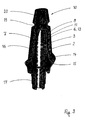
- an abutment cap 7 according to the invention as shown in Figs. 2 and 7 comprises means for defined rotational and lateral fixing in impression material applied by a dentist to the abutment cap when taking an impression of the teeth arrangement inside the mouth of a patient preferably in the form of at least one protrusion 10, located generally opposite to the connecting portion 11 of the cap 7 for cementing the cap 7 onto the abutment post 2.
- Such a configuration allows the use of a single cap 7 both for taking an impression and as a base for a veneering 12 later on by a dental laboratory.
- Present prefabricated dental prosthesis components are generally made of metal, usually titanium alloys or gold or gold based alloys, to ease appropriate trimming by the dental laboratory by machining the components to obtain the desired shape for preparing a dental prosthesis fitting into the dental arrangement of a patient.
- the components of the abutment set comprising a post 2 and a cap 7 are anatomically preconfigured and adapted to fit to each other without further machining by the customer, i.e. a dental laboratory preparing the dental prosthesis. Therefore the need for machining the prefabricated components can be minimized, if not omitted.
- the abutment post 2 and the abutment cap 7 of the abutment set according to the invention are made of a ceramic material comprising zirconium oxide and/or aluminum oxide.
- This enables the dentist and the patient to make use of the specific advantages both of prefabricated components and ceramics material, particularly with respect to patients suffering from metal alloy incompatibility. Further the long term stability of the prosthesis is improved as matching of the thermal expansion coefficient can easily be obtained, reducing the risk of cracks and the like.
- the protrusion 10 is partially or totally removable from the cap 7 by cutting, grinding or breaking prior to receiving the veneering 12. This ensures most properly exact reposition of the abutment cap 7 once fitted with the veneering 12 compared to the orientation when taking the impression inside the patient's mouth by the dentist, and easy handling by the laboratory.
- the dental technician may adjust the occlusal length of the cap. This allows him to optimize mechanical support for the veneering 12 against occlusal forces on the one hand and optical properties of the prosthesis on the other hand, particularly with an embodiment of the invention as shown in Fig. 3.
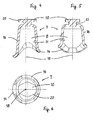
- An arrangement of the cap 7 with totally removed protrusion 10 is shown in Fig. 8 with a veneering 12 adapted to the anatomy of the patient being illustrated in dotted lines.
- the protrusion 10 may be of fungiform or hammerhead shape with a space 22 between a head section 20 and the body of the cap 7 so as to receive sufficient impression material lateral fixing of the cap 7 in the impression material applied by a dentist when taking an impression of the teeth arrangement inside the mouth cavity of a patient.
- a defined rotational fixing of the cap 7 in the impression material is obtained by non-circular shape of the head section 20 and its different extension in two directions in a plane generally perpendicular to the longitudinal axis 18 of the cap 7.
- the abutment cap 7 and the abutment post 2 having functional surface elements for providing a predetermined rotational orientation relative to each other. This can be obtained for example by a positive rotational fit between the cap 7 and the post 2, which may be in the form of a non-circular cross section of the hole 8 inside the cap 7 and a corresponding non circular cross section of a portion 13 of the post 2 for receiving the abutment cap 7, as can be seen from Figs. 4 to 6.
- such positive rotational fit between the cap 7 and the post 2 may be obtained by the shape of a bottom rim section 14 of the cap 7 and a correspondingly shaped collar 15 of the abutment post 2 as can be seen from Fig. 3.
- the rim section 14 is part of the anatomically pre-configuration of the cap 7, as can be seen particularly good in Figs. 2 and 7.
- the bottom rim section 14 surrounds the connecting portion 11 of the cap 7.
- the shape of the rim section 14 is adapted to the natural gingival contour.
- the embodiment according to the invention provides best esthetical results for the dental prosthesis as the prosthesis fits in the gingival situation of the patient's mouth like a natural tooth, and avoids that the dental implant can be seen from outside. On the other hand this is achieved without a need for trimming by the dental laboratory when preparing the prosthesis, thus further reducing the costs for the prosthesis while improving the quality of the result at the same time.
- the abutment post 2 has a portion 13 for receiving the abutment cap 7, and the surface of said portion 13 has a preconditioned surface generally ready for receiving cementum or adhesive for mechanical fixing of the abutment cap 7 to the post 2. This allows reduction of preparation work like blasting to be limited to what is needed for cleaning the post 2. Also the surface of said connecting portion 11 of the cap 7 is a preconditioned surface generally ready for receiving cementum or adhesive for rigid mechanical fixing to the abutment post 2. More further it is preferred that a receiving portion 16 for receiving the veneering 12 a preconditioned surface generally ready for receiving the veneering in a rigid in a mechanical fixing configuration, e.g. by firing.
- Fig. 3 shows an abutment set according to the invention with a cap 7 mounted on a post 2.
- the space between the portion 13 of the post 2 for receiving the abutment cap 7 and the connecting portion 11 of the cap 7 may receive the cementum for mechanically fixing the cap 7 and the post 2 together.
- the post 2 is to be mounted onto the implant 1 prior to fixing the cap 7 to the post 2 e.g. by way of a screw 5 not shown in Fig. 3.
- the embodiment of Fig 3 further shows an alternative arrangement for rotational positioning and fixing of the post 2 to the implant 1.
- a peg 6 there is provided a hexagonal portion 17 for positive fit into a corresponding hexagonal recess of an implant.
- Fig. 3 shows an alternative embodiment of a protrusion 10.
- a defined rotational fixing in impression material is obtained by a non-circular cross section of the protrusion 10 perpendicular to the longitudinal axis 18 of the cap 7.
- the lateral fixing in impression material applied by a dentist to the abutment cap when taking an impression of the teeth arrangement is obtained by a circumferential groove 19.
- the groove 19 also forms the basis for removing the protrusion 10 when the cap 7 is removed from the impression for adding the veneering 12 or a crown to the cap 7.
- a suitable method for manufacturing a dental prosthesis for mounting on a dental implant may comprise the steps of selecting a set of prefabricated abutment post 2 and abutment cap 7 of appropriate shape with respect to the dental situation of a patient, obtaining an impression of the abutment post 2 and abutment cap 7 removably fixed to the implant 1 within the dental arrangement inside the mouth of the patient, and adding a veneering 12 to the abutment cap 7 without further machining of the abutment cap 7 and the abutment post 2.
- the method according to the invention further includes the step of removing the abutment cap 7 from the impression, removing the protrusion 10 for rotational and lateral fixing of the abutment cap 7 to the impression, if any, prior to adding the veneering 12 to the abutment cap 7, mounting the abutment post 2 to the dental implant 1 and cementing the abutment cap 7 carrying the veneering 12 to the abutment post 2.
- the invention may be put into effect most effectively by treating a human or animal being with a dental prosthesis as described above.
- a dental prosthesis comprising an implant 1, an abutment post 2 and an abutment cap 7 as well as a veneering 12 or crown or the like according to what is described above.
Landscapes
- Health & Medical Sciences (AREA)
- Oral & Maxillofacial Surgery (AREA)
- Orthopedic Medicine & Surgery (AREA)
- Dentistry (AREA)
- Epidemiology (AREA)
- Life Sciences & Earth Sciences (AREA)
- Animal Behavior & Ethology (AREA)
- General Health & Medical Sciences (AREA)
- Public Health (AREA)
- Veterinary Medicine (AREA)
- Dental Prosthetics (AREA)
Priority Applications (10)
| Application Number | Priority Date | Filing Date | Title |
|---|---|---|---|
| ES05006115.9T ES2529350T3 (es) | 2005-03-21 | 2005-03-21 | Conjunto de pilar para un implante dental y método de fabricación de una prótesis dental |
| PT05006115T PT1704829E (pt) | 2005-03-21 | 2005-03-21 | Conjunto de pino para um implante dentário e método de fabrico de uma prótese dentária |
| EP20050006115 EP1704829B1 (fr) | 2005-03-21 | 2005-03-21 | Set de butées pour un implant dentaire et méthode de fabrication d'une prothèse dentaire |
| JP2008503050A JP5356014B2 (ja) | 2005-03-21 | 2006-03-17 | 歯科インプラント用のアバットメントセット |
| BRPI0608858-9A BRPI0608858A2 (pt) | 2005-03-21 | 2006-03-17 | conjunto de suporte para um implante dentÁrio, mÉtodo para fabricar uma pràtese dentÁria, e, pràtese dentÁria |
| CA2600556A CA2600556C (fr) | 2005-03-21 | 2006-03-17 | Assemblage de pivot pour un implant dentaire |
| PCT/US2006/009673 WO2006102054A1 (fr) | 2005-03-21 | 2006-03-17 | Assemblage de pivot pour un implant dentaire |
| CNA2006800093052A CN101163454A (zh) | 2005-03-21 | 2006-03-17 | 牙种植体的桥基套件 |
| TW095109673A TW200642667A (en) | 2005-03-21 | 2006-03-21 | Abutment set for a dental implant |
| US11/900,181 US20080008981A1 (en) | 2005-03-21 | 2007-09-10 | Abutment set for a dental implant |
Applications Claiming Priority (1)
| Application Number | Priority Date | Filing Date | Title |
|---|---|---|---|
| EP20050006115 EP1704829B1 (fr) | 2005-03-21 | 2005-03-21 | Set de butées pour un implant dentaire et méthode de fabrication d'une prothèse dentaire |
Publications (2)
| Publication Number | Publication Date |
|---|---|
| EP1704829A1 true EP1704829A1 (fr) | 2006-09-27 |
| EP1704829B1 EP1704829B1 (fr) | 2014-11-05 |
Family
ID=34934396
Family Applications (1)
| Application Number | Title | Priority Date | Filing Date |
|---|---|---|---|
| EP20050006115 Expired - Lifetime EP1704829B1 (fr) | 2005-03-21 | 2005-03-21 | Set de butées pour un implant dentaire et méthode de fabrication d'une prothèse dentaire |
Country Status (9)
| Country | Link |
|---|---|
| EP (1) | EP1704829B1 (fr) |
| JP (1) | JP5356014B2 (fr) |
| CN (1) | CN101163454A (fr) |
| BR (1) | BRPI0608858A2 (fr) |
| CA (1) | CA2600556C (fr) |
| ES (1) | ES2529350T3 (fr) |
| PT (1) | PT1704829E (fr) |
| TW (1) | TW200642667A (fr) |
| WO (1) | WO2006102054A1 (fr) |
Cited By (2)
| Publication number | Priority date | Publication date | Assignee | Title |
|---|---|---|---|---|
| US8187000B2 (en) * | 2007-01-18 | 2012-05-29 | Straumann Holding Ag | Impression cap |
| WO2018099594A3 (fr) * | 2016-12-01 | 2018-07-12 | Dentsply Implants Manufacturing Gmbh | Système comprenant un tenon radiculaire à pilier prothétique et un capuchon associé, ainsi qu'un outil servant à l'application du capuchon |
Families Citing this family (11)
| Publication number | Priority date | Publication date | Assignee | Title |
|---|---|---|---|---|
| US8007279B2 (en) * | 2005-06-17 | 2011-08-30 | Zimmer Dental, Inc. | Dental restorative system and components |
| DE202006006920U1 (de) * | 2006-04-25 | 2007-08-30 | Biomed Est. | Dentalimplantat |
| EP1894541B1 (fr) * | 2006-08-29 | 2013-03-20 | Straumann Holding AG | Pilier pour un implant dentaire |
| JP5789860B2 (ja) * | 2007-03-14 | 2015-10-07 | デンツプライ インターナショナル インコーポレーテッド | フィレットを有する人工橋脚歯 |
| WO2011125309A1 (fr) * | 2010-04-07 | 2011-10-13 | 有限会社シエスタ | Implant dentaire |
| WO2012113134A1 (fr) * | 2011-02-21 | 2012-08-30 | Ho Chih-Chung | Butée conique de blocage dotée d'une zone de faiblesse |
| CN104470462B (zh) * | 2012-07-19 | 2017-07-25 | 株式会社Gc | 牙科用块 |
| MX2016013728A (es) | 2014-04-22 | 2017-05-01 | T A G Medical Devices - Agriculture Coop Ltd | Implantes dentales. |
| WO2017141061A1 (fr) * | 2016-02-19 | 2017-08-24 | Elsner Edvin | Coiffe d'empreinte pour fabriquer une prothèse dentaire |
| LT6582B (lt) | 2017-03-14 | 2019-01-10 | Uab "Densartas" | Teleskopinė karūnėlė dantų protezui |
| BR102020020599A2 (pt) * | 2020-10-07 | 2022-04-19 | Jjgc Indústria E Comércio De Materiais Dentários S.A. | Componente protético multifuncional para fluxo convencional ou digital de instalação de prótese dentária sobre implante |
Citations (12)
| Publication number | Priority date | Publication date | Assignee | Title |
|---|---|---|---|---|
| US438048A (en) | 1890-10-07 | Martin n | ||
| WO1985002337A1 (fr) | 1983-11-25 | 1985-06-06 | Soederberg Per Olof | Implant de fixation de protheses dentaires |
| US4575340A (en) * | 1985-02-04 | 1986-03-11 | Lustig Leopold P | Precision dental restorative system |
| US5125840A (en) | 1990-09-08 | 1992-06-30 | Eberle Medizintechnische Element Gmbh | Enossal single tooth implant with twisting restraint |
| US5199873A (en) | 1990-01-15 | 1993-04-06 | Friedrichsfeld Ag Keramik- Und Kunststoffwerke | Dental implant |
| EP0707835A1 (fr) | 1994-10-17 | 1996-04-24 | Degussa Aktiengesellschaft | Implant dentaire diphasé |
| WO2001097706A1 (fr) * | 2000-06-19 | 2001-12-27 | Nobel Biocare Ab | Coiffe comprenant des espaceurs |
| US20020177106A1 (en) | 1999-09-22 | 2002-11-28 | Dittmar May | Implant-supported dental prosthesis and a process for its production |
| WO2003105710A2 (fr) * | 2002-06-15 | 2003-12-24 | Neoss Limited | Prothese |
| US20040096804A1 (en) * | 2001-04-27 | 2004-05-20 | Martin Vogt | Assembly for handling an implant |
| WO2004054464A2 (fr) * | 2002-12-13 | 2004-07-01 | Stefan Neumeyer | Pilier pour un implant dentaire, implant dentaire comprenant un tel pilier et procede pour produire une prothese dentaire par utilisation de cet implant dentaire |
| US20050014108A1 (en) * | 2003-05-16 | 2005-01-20 | Wohrle Peter S. | Dental implant system |
-
2005
- 2005-03-21 ES ES05006115.9T patent/ES2529350T3/es not_active Expired - Lifetime
- 2005-03-21 PT PT05006115T patent/PT1704829E/pt unknown
- 2005-03-21 EP EP20050006115 patent/EP1704829B1/fr not_active Expired - Lifetime
-
2006
- 2006-03-17 WO PCT/US2006/009673 patent/WO2006102054A1/fr not_active Ceased
- 2006-03-17 BR BRPI0608858-9A patent/BRPI0608858A2/pt not_active IP Right Cessation
- 2006-03-17 CN CNA2006800093052A patent/CN101163454A/zh active Pending
- 2006-03-17 CA CA2600556A patent/CA2600556C/fr not_active Expired - Lifetime
- 2006-03-17 JP JP2008503050A patent/JP5356014B2/ja not_active Expired - Fee Related
- 2006-03-21 TW TW095109673A patent/TW200642667A/zh unknown
Patent Citations (14)
| Publication number | Priority date | Publication date | Assignee | Title |
|---|---|---|---|---|
| US438048A (en) | 1890-10-07 | Martin n | ||
| WO1985002337A1 (fr) | 1983-11-25 | 1985-06-06 | Soederberg Per Olof | Implant de fixation de protheses dentaires |
| US4772204A (en) | 1983-11-25 | 1988-09-20 | Astra Meditec Aktiebolag | Implant for attachment of dental prostheses |
| US4575340A (en) * | 1985-02-04 | 1986-03-11 | Lustig Leopold P | Precision dental restorative system |
| US5199873A (en) | 1990-01-15 | 1993-04-06 | Friedrichsfeld Ag Keramik- Und Kunststoffwerke | Dental implant |
| US5125840A (en) | 1990-09-08 | 1992-06-30 | Eberle Medizintechnische Element Gmbh | Enossal single tooth implant with twisting restraint |
| EP0707835A1 (fr) | 1994-10-17 | 1996-04-24 | Degussa Aktiengesellschaft | Implant dentaire diphasé |
| US5674072A (en) | 1994-10-17 | 1997-10-07 | Degussa Aktiengesellschaft | Two-phase tooth implant |
| US20020177106A1 (en) | 1999-09-22 | 2002-11-28 | Dittmar May | Implant-supported dental prosthesis and a process for its production |
| WO2001097706A1 (fr) * | 2000-06-19 | 2001-12-27 | Nobel Biocare Ab | Coiffe comprenant des espaceurs |
| US20040096804A1 (en) * | 2001-04-27 | 2004-05-20 | Martin Vogt | Assembly for handling an implant |
| WO2003105710A2 (fr) * | 2002-06-15 | 2003-12-24 | Neoss Limited | Prothese |
| WO2004054464A2 (fr) * | 2002-12-13 | 2004-07-01 | Stefan Neumeyer | Pilier pour un implant dentaire, implant dentaire comprenant un tel pilier et procede pour produire une prothese dentaire par utilisation de cet implant dentaire |
| US20050014108A1 (en) * | 2003-05-16 | 2005-01-20 | Wohrle Peter S. | Dental implant system |
Cited By (4)
| Publication number | Priority date | Publication date | Assignee | Title |
|---|---|---|---|---|
| US8187000B2 (en) * | 2007-01-18 | 2012-05-29 | Straumann Holding Ag | Impression cap |
| WO2018099594A3 (fr) * | 2016-12-01 | 2018-07-12 | Dentsply Implants Manufacturing Gmbh | Système comprenant un tenon radiculaire à pilier prothétique et un capuchon associé, ainsi qu'un outil servant à l'application du capuchon |
| RU2725558C1 (ru) * | 2016-12-01 | 2020-07-02 | Дентсплай Имплантс Мэньюфэкчуринг Гмбх | Конструкция, содержащая штифт абатмента и относящийся к нему колпачок, а также инструмент для наложения колпачка |
| US11344389B2 (en) | 2016-12-01 | 2022-05-31 | Dentsply Implants Manufacturing Gmbh | Arrangement comprising an abutment post and an appurtenant cap, as well as a tool for application of the cap |
Also Published As
| Publication number | Publication date |
|---|---|
| PT1704829E (pt) | 2015-02-10 |
| EP1704829B1 (fr) | 2014-11-05 |
| JP2008539809A (ja) | 2008-11-20 |
| TW200642667A (en) | 2006-12-16 |
| ES2529350T3 (es) | 2015-02-19 |
| CA2600556C (fr) | 2013-10-22 |
| CA2600556A1 (fr) | 2006-09-28 |
| JP5356014B2 (ja) | 2013-12-04 |
| CN101163454A (zh) | 2008-04-16 |
| BRPI0608858A2 (pt) | 2012-07-31 |
| WO2006102054A1 (fr) | 2006-09-28 |
Similar Documents
| Publication | Publication Date | Title |
|---|---|---|
| CA2319946C (fr) | Prothese dentaire supportee par un implant, ainsi que son procede de production | |
| US20110065065A1 (en) | Blank and method for producing a dental prosthesis | |
| US5630717A (en) | Dental implant bar system and method | |
| US7901209B2 (en) | Method for automatically creating a dental superstructure for joining to an implant | |
| EP1523284B1 (fr) | Prothèse dentale | |
| EP0473262B1 (fr) | Bague pour implant dentaire et système de support | |
| US6666684B1 (en) | Impression and foundation system for implant-supported prosthesis | |
| CA2649611C (fr) | Implant dentaire et son procede de fabrication | |
| KR101091587B1 (ko) | 치과용 임플란트 지대주 | |
| US20150173864A1 (en) | Abutment assembly for dental implants | |
| CN104640516B (zh) | 成形的且可弯曲的假基牙和角度调整方法 | |
| CA2600556C (fr) | Assemblage de pivot pour un implant dentaire | |
| US20080008981A1 (en) | Abutment set for a dental implant | |
| CN103796612A (zh) | 能够收容以多种角度来制作的桩核冠并且附着帽时具有牙龈成形器的功能的基牙和利用该基牙的种植体的制造方法及种植手术方法 | |
| US20100003635A1 (en) | Dental implant | |
| EP1663045B1 (fr) | Systeme d'implant dentaire | |
| US20180125614A1 (en) | Dental prostheses | |
| HK1116387A (en) | Abutment set for a dental implant | |
| WO2010100163A2 (fr) | Superstructure pour un système de prothèse dentaire et procédé de fabrication correspondant | |
| HK1084316B (en) | Dental implant system |
Legal Events
| Date | Code | Title | Description |
|---|---|---|---|
| PUAI | Public reference made under article 153(3) epc to a published international application that has entered the european phase |
Free format text: ORIGINAL CODE: 0009012 |
|
| AK | Designated contracting states |
Kind code of ref document: A1 Designated state(s): AT BE BG CH CY CZ DE DK EE ES FI FR GB GR HU IE IS IT LI LT LU MC NL PL PT RO SE SI SK TR |
|
| AX | Request for extension of the european patent |
Extension state: AL BA HR LV MK YU |
|
| 17P | Request for examination filed |
Effective date: 20061114 |
|
| 17Q | First examination report despatched |
Effective date: 20070116 |
|
| AKX | Designation fees paid |
Designated state(s): AT BE BG CH CY CZ DE DK EE ES FI FR GB GR HU IE IS IT LI LT LU MC NL PL PT RO SE SI SK TR |
|
| GRAP | Despatch of communication of intention to grant a patent |
Free format text: ORIGINAL CODE: EPIDOSNIGR1 |
|
| RIC1 | Information provided on ipc code assigned before grant |
Ipc: A61C 13/00 20060101ALI20140417BHEP Ipc: A61C 8/00 20060101AFI20140417BHEP |
|
| INTG | Intention to grant announced |
Effective date: 20140520 |
|
| RAP1 | Party data changed (applicant data changed or rights of an application transferred) |
Owner name: DENTSPLY IMPLANTS MANUFACTURING GMBH |
|
| GRAS | Grant fee paid |
Free format text: ORIGINAL CODE: EPIDOSNIGR3 |
|
| GRAA | (expected) grant |
Free format text: ORIGINAL CODE: 0009210 |
|
| AK | Designated contracting states |
Kind code of ref document: B1 Designated state(s): AT BE BG CH CY CZ DE DK EE ES FI FR GB GR HU IE IS IT LI LT LU MC NL PL PT RO SE SI SK TR |
|
| REG | Reference to a national code |
Ref country code: GB Ref legal event code: FG4D |
|
| REG | Reference to a national code |
Ref country code: CH Ref legal event code: EP |
|
| REG | Reference to a national code |
Ref country code: AT Ref legal event code: REF Ref document number: 694178 Country of ref document: AT Kind code of ref document: T Effective date: 20141115 |
|
| REG | Reference to a national code |
Ref country code: IE Ref legal event code: FG4D |
|
| REG | Reference to a national code |
Ref country code: DE Ref legal event code: R096 Ref document number: 602005045065 Country of ref document: DE Effective date: 20141218 |
|
| REG | Reference to a national code |
Ref country code: CH Ref legal event code: NV Representative=s name: E. BLUM AND CO. AG PATENT- UND MARKENANWAELTE , CH |
|
| REG | Reference to a national code |
Ref country code: PT Ref legal event code: SC4A Free format text: AVAILABILITY OF NATIONAL TRANSLATION Effective date: 20150203 |
|
| REG | Reference to a national code |
Ref country code: ES Ref legal event code: FG2A Ref document number: 2529350 Country of ref document: ES Kind code of ref document: T3 Effective date: 20150219 |
|
| REG | Reference to a national code |
Ref country code: SE Ref legal event code: TRGR |
|
| REG | Reference to a national code |
Ref country code: NL Ref legal event code: VDEP Effective date: 20141105 |
|
| REG | Reference to a national code |
Ref country code: FR Ref legal event code: PLFP Year of fee payment: 11 |
|
| REG | Reference to a national code |
Ref country code: LT Ref legal event code: MG4D |
|
| PG25 | Lapsed in a contracting state [announced via postgrant information from national office to epo] |
Ref country code: IS Free format text: LAPSE BECAUSE OF FAILURE TO SUBMIT A TRANSLATION OF THE DESCRIPTION OR TO PAY THE FEE WITHIN THE PRESCRIBED TIME-LIMIT Effective date: 20150305 Ref country code: FI Free format text: LAPSE BECAUSE OF FAILURE TO SUBMIT A TRANSLATION OF THE DESCRIPTION OR TO PAY THE FEE WITHIN THE PRESCRIBED TIME-LIMIT Effective date: 20141105 Ref country code: LT Free format text: LAPSE BECAUSE OF FAILURE TO SUBMIT A TRANSLATION OF THE DESCRIPTION OR TO PAY THE FEE WITHIN THE PRESCRIBED TIME-LIMIT Effective date: 20141105 Ref country code: NL Free format text: LAPSE BECAUSE OF FAILURE TO SUBMIT A TRANSLATION OF THE DESCRIPTION OR TO PAY THE FEE WITHIN THE PRESCRIBED TIME-LIMIT Effective date: 20141105 |
|
| PG25 | Lapsed in a contracting state [announced via postgrant information from national office to epo] |
Ref country code: PL Free format text: LAPSE BECAUSE OF FAILURE TO SUBMIT A TRANSLATION OF THE DESCRIPTION OR TO PAY THE FEE WITHIN THE PRESCRIBED TIME-LIMIT Effective date: 20141105 Ref country code: GR Free format text: LAPSE BECAUSE OF FAILURE TO SUBMIT A TRANSLATION OF THE DESCRIPTION OR TO PAY THE FEE WITHIN THE PRESCRIBED TIME-LIMIT Effective date: 20150206 Ref country code: CY Free format text: LAPSE BECAUSE OF FAILURE TO SUBMIT A TRANSLATION OF THE DESCRIPTION OR TO PAY THE FEE WITHIN THE PRESCRIBED TIME-LIMIT Effective date: 20141105 |
|
| PG25 | Lapsed in a contracting state [announced via postgrant information from national office to epo] |
Ref country code: EE Free format text: LAPSE BECAUSE OF FAILURE TO SUBMIT A TRANSLATION OF THE DESCRIPTION OR TO PAY THE FEE WITHIN THE PRESCRIBED TIME-LIMIT Effective date: 20141105 Ref country code: CZ Free format text: LAPSE BECAUSE OF FAILURE TO SUBMIT A TRANSLATION OF THE DESCRIPTION OR TO PAY THE FEE WITHIN THE PRESCRIBED TIME-LIMIT Effective date: 20141105 Ref country code: RO Free format text: LAPSE BECAUSE OF FAILURE TO SUBMIT A TRANSLATION OF THE DESCRIPTION OR TO PAY THE FEE WITHIN THE PRESCRIBED TIME-LIMIT Effective date: 20141105 Ref country code: SK Free format text: LAPSE BECAUSE OF FAILURE TO SUBMIT A TRANSLATION OF THE DESCRIPTION OR TO PAY THE FEE WITHIN THE PRESCRIBED TIME-LIMIT Effective date: 20141105 Ref country code: DK Free format text: LAPSE BECAUSE OF FAILURE TO SUBMIT A TRANSLATION OF THE DESCRIPTION OR TO PAY THE FEE WITHIN THE PRESCRIBED TIME-LIMIT Effective date: 20141105 |
|
| REG | Reference to a national code |
Ref country code: DE Ref legal event code: R097 Ref document number: 602005045065 Country of ref document: DE |
|
| PLBE | No opposition filed within time limit |
Free format text: ORIGINAL CODE: 0009261 |
|
| STAA | Information on the status of an ep patent application or granted ep patent |
Free format text: STATUS: NO OPPOSITION FILED WITHIN TIME LIMIT |
|
| 26N | No opposition filed |
Effective date: 20150806 |
|
| PG25 | Lapsed in a contracting state [announced via postgrant information from national office to epo] |
Ref country code: MC Free format text: LAPSE BECAUSE OF FAILURE TO SUBMIT A TRANSLATION OF THE DESCRIPTION OR TO PAY THE FEE WITHIN THE PRESCRIBED TIME-LIMIT Effective date: 20141105 |
|
| PG25 | Lapsed in a contracting state [announced via postgrant information from national office to epo] |
Ref country code: SI Free format text: LAPSE BECAUSE OF FAILURE TO SUBMIT A TRANSLATION OF THE DESCRIPTION OR TO PAY THE FEE WITHIN THE PRESCRIBED TIME-LIMIT Effective date: 20141105 |
|
| REG | Reference to a national code |
Ref country code: FR Ref legal event code: PLFP Year of fee payment: 12 |
|
| PGFP | Annual fee paid to national office [announced via postgrant information from national office to epo] |
Ref country code: IE Payment date: 20160323 Year of fee payment: 12 Ref country code: LU Payment date: 20160324 Year of fee payment: 12 Ref country code: TR Payment date: 20160224 Year of fee payment: 12 |
|
| REG | Reference to a national code |
Ref country code: AT Ref legal event code: UEP Ref document number: 694178 Country of ref document: AT Kind code of ref document: T Effective date: 20141105 |
|
| PGFP | Annual fee paid to national office [announced via postgrant information from national office to epo] |
Ref country code: AT Payment date: 20160322 Year of fee payment: 12 Ref country code: PT Payment date: 20160321 Year of fee payment: 12 |
|
| REG | Reference to a national code |
Ref country code: FR Ref legal event code: PLFP Year of fee payment: 13 |
|
| PG25 | Lapsed in a contracting state [announced via postgrant information from national office to epo] |
Ref country code: BG Free format text: LAPSE BECAUSE OF FAILURE TO SUBMIT A TRANSLATION OF THE DESCRIPTION OR TO PAY THE FEE WITHIN THE PRESCRIBED TIME-LIMIT Effective date: 20141105 Ref country code: HU Free format text: LAPSE BECAUSE OF FAILURE TO SUBMIT A TRANSLATION OF THE DESCRIPTION OR TO PAY THE FEE WITHIN THE PRESCRIBED TIME-LIMIT; INVALID AB INITIO Effective date: 20050321 |
|
| PGFP | Annual fee paid to national office [announced via postgrant information from national office to epo] |
Ref country code: BE Payment date: 20170321 Year of fee payment: 13 |
|
| REG | Reference to a national code |
Ref country code: AT Ref legal event code: MM01 Ref document number: 694178 Country of ref document: AT Kind code of ref document: T Effective date: 20170321 |
|
| PG25 | Lapsed in a contracting state [announced via postgrant information from national office to epo] |
Ref country code: PT Free format text: LAPSE BECAUSE OF NON-PAYMENT OF DUE FEES Effective date: 20170921 |
|
| REG | Reference to a national code |
Ref country code: IE Ref legal event code: MM4A |
|
| PG25 | Lapsed in a contracting state [announced via postgrant information from national office to epo] |
Ref country code: AT Free format text: LAPSE BECAUSE OF NON-PAYMENT OF DUE FEES Effective date: 20170321 Ref country code: LU Free format text: LAPSE BECAUSE OF NON-PAYMENT OF DUE FEES Effective date: 20170321 |
|
| PG25 | Lapsed in a contracting state [announced via postgrant information from national office to epo] |
Ref country code: IE Free format text: LAPSE BECAUSE OF NON-PAYMENT OF DUE FEES Effective date: 20170321 |
|
| REG | Reference to a national code |
Ref country code: FR Ref legal event code: PLFP Year of fee payment: 14 |
|
| REG | Reference to a national code |
Ref country code: BE Ref legal event code: FP Effective date: 20150203 Ref country code: BE Ref legal event code: MM Effective date: 20180331 |
|
| PG25 | Lapsed in a contracting state [announced via postgrant information from national office to epo] |
Ref country code: BE Free format text: LAPSE BECAUSE OF NON-PAYMENT OF DUE FEES Effective date: 20180331 |
|
| PGFP | Annual fee paid to national office [announced via postgrant information from national office to epo] |
Ref country code: ES Payment date: 20190401 Year of fee payment: 15 |
|
| PGFP | Annual fee paid to national office [announced via postgrant information from national office to epo] |
Ref country code: IT Payment date: 20210211 Year of fee payment: 17 Ref country code: FR Payment date: 20210210 Year of fee payment: 17 Ref country code: CH Payment date: 20210317 Year of fee payment: 17 |
|
| PGFP | Annual fee paid to national office [announced via postgrant information from national office to epo] |
Ref country code: DE Payment date: 20210310 Year of fee payment: 17 Ref country code: SE Payment date: 20210311 Year of fee payment: 17 Ref country code: GB Payment date: 20210310 Year of fee payment: 17 |
|
| REG | Reference to a national code |
Ref country code: ES Ref legal event code: FD2A Effective date: 20210802 |
|
| PG25 | Lapsed in a contracting state [announced via postgrant information from national office to epo] |
Ref country code: ES Free format text: LAPSE BECAUSE OF NON-PAYMENT OF DUE FEES Effective date: 20200322 |
|
| PG25 | Lapsed in a contracting state [announced via postgrant information from national office to epo] |
Ref country code: TR Free format text: LAPSE BECAUSE OF NON-PAYMENT OF DUE FEES Effective date: 20170321 |
|
| REG | Reference to a national code |
Ref country code: DE Ref legal event code: R119 Ref document number: 602005045065 Country of ref document: DE |
|
| REG | Reference to a national code |
Ref country code: CH Ref legal event code: PL |
|
| GBPC | Gb: european patent ceased through non-payment of renewal fee |
Effective date: 20220321 |
|
| PG25 | Lapsed in a contracting state [announced via postgrant information from national office to epo] |
Ref country code: SE Free format text: LAPSE BECAUSE OF NON-PAYMENT OF DUE FEES Effective date: 20220322 Ref country code: LI Free format text: LAPSE BECAUSE OF NON-PAYMENT OF DUE FEES Effective date: 20220331 Ref country code: GB Free format text: LAPSE BECAUSE OF NON-PAYMENT OF DUE FEES Effective date: 20220321 Ref country code: FR Free format text: LAPSE BECAUSE OF NON-PAYMENT OF DUE FEES Effective date: 20220331 Ref country code: DE Free format text: LAPSE BECAUSE OF NON-PAYMENT OF DUE FEES Effective date: 20221001 Ref country code: CH Free format text: LAPSE BECAUSE OF NON-PAYMENT OF DUE FEES Effective date: 20220331 |
|
| PG25 | Lapsed in a contracting state [announced via postgrant information from national office to epo] |
Ref country code: IT Free format text: LAPSE BECAUSE OF NON-PAYMENT OF DUE FEES Effective date: 20220321 |