EP1704966A2 - Trennscheibe - Google Patents
Trennscheibe Download PDFInfo
- Publication number
- EP1704966A2 EP1704966A2 EP06003910A EP06003910A EP1704966A2 EP 1704966 A2 EP1704966 A2 EP 1704966A2 EP 06003910 A EP06003910 A EP 06003910A EP 06003910 A EP06003910 A EP 06003910A EP 1704966 A2 EP1704966 A2 EP 1704966A2
- Authority
- EP
- European Patent Office
- Prior art keywords
- wheel
- profile
- face
- profiles
- faces
- Prior art date
- Legal status (The legal status is an assumption and is not a legal conclusion. Google has not performed a legal analysis and makes no representation as to the accuracy of the status listed.)
- Granted
Links
- 238000005520 cutting process Methods 0.000 title claims abstract description 15
- 238000009423 ventilation Methods 0.000 claims description 4
- 238000013459 approach Methods 0.000 claims description 2
- 239000000463 material Substances 0.000 description 6
- 239000003086 colorant Substances 0.000 description 3
- 238000001816 cooling Methods 0.000 description 3
- 238000000465 moulding Methods 0.000 description 3
- 239000003082 abrasive agent Substances 0.000 description 2
- 238000005452 bending Methods 0.000 description 2
- 238000005457 optimization Methods 0.000 description 2
- 239000000123 paper Substances 0.000 description 2
- 239000004033 plastic Substances 0.000 description 2
- 239000007787 solid Substances 0.000 description 2
- 239000011230 binding agent Substances 0.000 description 1
- 230000003247 decreasing effect Effects 0.000 description 1
- 230000000994 depressogenic effect Effects 0.000 description 1
- 230000004069 differentiation Effects 0.000 description 1
- 238000009826 distribution Methods 0.000 description 1
- 230000000694 effects Effects 0.000 description 1
- 239000008187 granular material Substances 0.000 description 1
- 238000004519 manufacturing process Methods 0.000 description 1
- 239000002184 metal Substances 0.000 description 1
- 230000005012 migration Effects 0.000 description 1
- 238000013508 migration Methods 0.000 description 1
- 239000000203 mixture Substances 0.000 description 1
- 230000035515 penetration Effects 0.000 description 1
- 230000035699 permeability Effects 0.000 description 1
- 239000000049 pigment Substances 0.000 description 1
- 239000012858 resilient material Substances 0.000 description 1
- 230000004044 response Effects 0.000 description 1
- 239000007779 soft material Substances 0.000 description 1
- 239000000126 substance Substances 0.000 description 1
Images


Classifications
-
- B—PERFORMING OPERATIONS; TRANSPORTING
- B24—GRINDING; POLISHING
- B24D—TOOLS FOR GRINDING, BUFFING OR SHARPENING
- B24D5/00—Bonded abrasive wheels, or wheels with inserted abrasive blocks, designed for acting only by their periphery; Bushings or mountings therefor
- B24D5/12—Cut-off wheels
Definitions
- the present invention relates to an improved cutting wheel.
- Thin, flat and depressed center cutting wheels consist of a thin disk of abrasive material, typically molded from a mixture of granules of suitable hardness and binders, and having hole at its center, optionally reinforced, for mounting it onto a rotating spindle.
- the opposite faces of these wheels are usually flat and parallel to define a constant thickness of the abrasive disk.
- the forward motion imparted to the cut-off wheel is parallel to the plane of the wheel itself, thereby causing the workpiece to be cut across.
- both faces of the wheel rub against the cut surfaces generated by cutting the workpiece, thereby generating high frictions, and the wheel fits in the gap defined by such surfaces, thereby making chip removal, ventilation of the working area, hence cooling, rather difficult.
- the specific object of this invention is to provide such improvements by proposing an improved cutting wheel that is optimized as compared with prior art, particularly in terms of versatility, resistance and quality of the cut surfaces formed on the workpieces and easier penetration in solid section cuts.
- Another object of the invention is to accomplish the above tasks by providing a simple structure, that ensures relatively easy practical implementation, safe use and effective operation, as well as a relatively low cost.
- the present improved cutting wheel which comprises a disk-shaped abrasive body having two opposite faces, characterized in that said body has a non-uniform thickness.
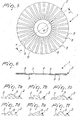
- an improved cutting wheel has been generally designated by numeral 1.
- the wheel 1 comprises a disk-shaped abrasive body 2 having two opposite faces 3, with an aperture 4 of any shape, optionally reinforced, formed at its center, for fitting it to a conventional spindle.
- the body 2 has a non-uniform thickness throughout its extension.
- the body 2 has at least one raised profile 5 associated to at least one of the faces 3, which may be added to such face or, preferably, formed of one piece therewith, such as by molding.
- This profile may be formed by a special mold cavity, which may be either empty or filled with a resilient material (e.g. rubber of any type), or by fitting smooth molds with perforated disks having special patterns to form the raised profile.
- a resilient material e.g. rubber of any type
- the profile 5 preferably has an elongate shape, to form a sort of rib, and has a substantially straight or curvilinear extension (arc of a circle, arc of an ellipse, or else).
- the profile 5 may extend in an essentially radial direction from the face 3.
- the profile 5 may connect smoothly to the surrounding portion of the face 5, to prevent impacts with the workpiece, but it may also have no smooth connection thereto.
- the profile 5 has a substantially constant thickness at least throughout its central portion, preferably of less than 0,001 m, and its size transverse its length and parallel to the face 3 is either substantially constant, or increasing or decreasing as it approaches the periphery of the face.
- the wheel 1 advantageously has a plurality of profiles 5 arranged near the periphery of the face 3.
- the profiles 5 are preferably arranged in succession, with a substantially constant angular pitch or in symmetric sets (also for balancing purposes, considering that these are high-speed rotating bodies) over an annular band of any size on face 3.
- the wheel 1 has a plurality of grooves 6 for removing chips formed during processing and/or ventilation and cooling of the working area, which are defined between two successive profiles 5 of the above succession.
- the wheel 1 may have a preferred direction of rotation, for improved chip removal and enhanced cooling of the cutting area.
- the wheel 1 preferably has profiles 5 associated to or made of one piece with each of the faces 3; the profiles 5 on the two faces 3 may either have matching angular phase positions or be alternated or offset through a desired angle.
- the inventive conformation is particularly advantageous for wheels 1 whose diameter is of 0.05 m to 0.35 m and whose thickness is of the order of about 1/60 of the diameter, or less.
- Figure 1 shows a first embodiment of the wheel of the invention, in which the faces 3, one whereof is only visible in the figure, are shaped to define a plurality of slightly curved profiles 5, arranged in succession over an annular band.
- the profiles 5 are arranged over each face 3 with their convexities oriented in the same direction and with outward inclinations to the radius, either constant or not, in the direction opposite to the direction of rotation.
- Figure 2 shows a second embodiment of the wheel of the invention, in which the faces 3, one whereof is only visible in the figure, are shaped to define a plurality of curvilinear profiles 5, arranged in succession over an annular band.
- the profiles 5 are arranged over each face with their convexities oriented in the same direction, and with their ends lying on respective symmetric radial directions.
- Figure 3 shows a third embodiment of the wheel of the invention, in which the faces 3, one whereof is only visible in the figure, are shaped to define a plurality of zigzag profiles 5, extending along respective broken lines arranged in succession over an annular band.
- Figure 4 shows a fourth embodiment of the wheel of the invention, in which the faces 3, one whereof is only visible in the figure, are shaped to define a plurality of straight profiles 5 of different lengths, inclined in respective symmetric radial directions and arranged in succession with a constant angular pitch over an annular band.
- the longer profiles 5 alternate with shorter profiles.
- Figures 5 and 6 show a fifth embodiment of the wheel of the invention, in which the faces 3, one whereof is only visible in the figure, are shaped to define a plurality of straight profiles 5 of equal lengths, inclined in respective symmetric radial directions and arranged in succession with a constant angular pitch over an annular band.
- the abrasive material will have a non uniform density distribution, namely lower at the profiles, where the molding volume within the molds is larger, thereby affording a higher versatility of use in response to the various types of material to be cut.
- the areas having a higher density and hardness are more effective with soft materials, whereas the areas having a lower density are more suitable for processing harder materials.
- the invention so conceived provides various areas of different densities, wherein the ratio between such areas of different densities varies as required, and in view of performance optimization.
- the provision of raised profiles allows the inventive wheels to have a higher bending strength as well as a higher lateral stability as compared with prior art wheels of equal thickness.
- the invention is particularly useful in the manufacture of the very thin cutting wheels, which have been increasingly popular in recent years and that, for the diameters of 115 mm and 125 mm, are being sold with thicknesses of 0.8 mm and even less; these traditional wheels have no lateral bending strength and the invention may considerably improve such strength.
- the wheel of the invention has particularly pleasing aesthetic qualities; such qualities may be enhanced by adding color to the raised profiles or cavities, through the use of various colors or materials (plastic materials, colored papers, combinations of papers and plastic or metal films, having either uniform colors all over the surface of different colors for the raised portions and the background) to obtain multicolored effects and customize the wheel. Color differentiation may be also obtained by chemical or mechanical migration/reaction of pigments or materials within the body of the wheel, which may migrate in various manners to the side surfaces as a function of different densities or permeabilities of the lateral films.
Landscapes
- Engineering & Computer Science (AREA)
- Mechanical Engineering (AREA)
- Polishing Bodies And Polishing Tools (AREA)
- Finish Polishing, Edge Sharpening, And Grinding By Specific Grinding Devices (AREA)
- Turning (AREA)
- Control And Other Processes For Unpacking Of Materials (AREA)
Priority Applications (1)
| Application Number | Priority Date | Filing Date | Title |
|---|---|---|---|
| PL06003910T PL1704966T3 (pl) | 2005-03-23 | 2006-02-27 | Tarcza do cięcia |
Applications Claiming Priority (1)
| Application Number | Priority Date | Filing Date | Title |
|---|---|---|---|
| IT000005U ITMO20050005U1 (it) | 2005-03-23 | 2005-03-23 | Mola da taglio perfezionata |
Publications (3)
| Publication Number | Publication Date |
|---|---|
| EP1704966A2 true EP1704966A2 (de) | 2006-09-27 |
| EP1704966A3 EP1704966A3 (de) | 2007-07-18 |
| EP1704966B1 EP1704966B1 (de) | 2009-12-16 |
Family
ID=37035828
Family Applications (1)
| Application Number | Title | Priority Date | Filing Date |
|---|---|---|---|
| EP06003910A Expired - Lifetime EP1704966B1 (de) | 2005-03-23 | 2006-02-27 | Trennscheibe |
Country Status (7)
| Country | Link |
|---|---|
| US (1) | US7364502B2 (de) |
| EP (1) | EP1704966B1 (de) |
| AT (1) | ATE452002T1 (de) |
| CA (1) | CA2537605C (de) |
| DE (1) | DE602006011069D1 (de) |
| IT (1) | ITMO20050005U1 (de) |
| PL (1) | PL1704966T3 (de) |
Cited By (1)
| Publication number | Priority date | Publication date | Assignee | Title |
|---|---|---|---|---|
| EP1982796A1 (de) * | 2007-04-20 | 2008-10-22 | Tyrolit Schleifmittelwerke Swarovski KG | Schleifscheibe |
Families Citing this family (6)
| Publication number | Priority date | Publication date | Assignee | Title |
|---|---|---|---|---|
| US8277291B2 (en) * | 2007-05-04 | 2012-10-02 | Professional Tool Manufacturing, Llc | Abrasive slotted disc with controlled axial displacement of a workpiece |
| US20090081931A1 (en) * | 2007-09-21 | 2009-03-26 | Hantover, Inc. | Blade dressing tool |
| IT1395952B1 (it) * | 2009-09-25 | 2012-11-02 | Adi S P A | Disco abrasivo per mola multi-disco, particolarmente per lavorazione di materiali lapidei ed affini e mola includente detto disco |
| USD658005S1 (en) | 2010-07-09 | 2012-04-24 | Grace Manufacturing, Inc. | Culinary cutting blade |
| US9149913B2 (en) | 2012-12-31 | 2015-10-06 | Saint-Gobain Abrasives, Inc. | Abrasive article having shaped segments |
| JP7039120B2 (ja) * | 2017-02-02 | 2022-03-22 | 株式会社ディスコ | 切削ブレード及び切削方法 |
Citations (5)
| Publication number | Priority date | Publication date | Assignee | Title |
|---|---|---|---|---|
| FR963496A (de) | 1950-07-11 | |||
| US3292311A (en) | 1961-12-06 | 1966-12-20 | James J Hensley | Abrasive wheels |
| US5769700A (en) | 1996-09-10 | 1998-06-23 | Norton Company | Grinding wheel |
| EP1050375A1 (de) | 1998-11-20 | 2000-11-08 | Sankyo Diamond Industrial Co., Ltd. | Diamanttrennscheibe und deren herstellungsverfahren |
| JP2003053670A (ja) | 2001-08-15 | 2003-02-26 | Rex Industries Co Ltd | ダイヤモンドブレードのチップ構造 |
Family Cites Families (27)
| Publication number | Priority date | Publication date | Assignee | Title |
|---|---|---|---|---|
| US970618A (en) * | 1908-01-31 | 1910-09-20 | Roland Gardner | Abrading-wheel. |
| US1641799A (en) * | 1925-08-31 | 1927-09-06 | Springfield Mfg Co | Sectional grinding wheel |
| US2795903A (en) * | 1955-10-24 | 1957-06-18 | Titcomb Albert Shepard | Clamp to secure an abrasive segment on a rotary chuck |
| US2883807A (en) * | 1956-09-18 | 1959-04-28 | Titcomb Albert Shepard | Segmental bonded abrasive bodies |
| US3121299A (en) * | 1962-07-19 | 1964-02-18 | Pittsburgh Plate Glass Co | Glass grinding runner |
| GB1060405A (en) * | 1964-05-25 | 1967-03-01 | Impregnated Diamond Prod Ltd | Improvements in diamond impregnated tools |
| US3745719A (en) * | 1971-12-13 | 1973-07-17 | F Oswald | Grinding wheel for floor grinding machine |
| US3889430A (en) * | 1972-05-17 | 1975-06-17 | S P A M | Abrasive tools |
| US4624237A (en) * | 1984-06-08 | 1986-11-25 | Jiro Inoue | Diamond saw |
| DE3513687A1 (de) * | 1985-04-16 | 1986-10-30 | Claudio 8962 Pfronten Mussner | Diamanttrennscheibe |
| FR2666533B1 (fr) * | 1990-09-12 | 1993-07-23 | Cecrops Sa | Disque abrasif performant. |
| JP3242307B2 (ja) * | 1995-11-02 | 2001-12-25 | ノリタケダイヤ株式会社 | 回転円盤カッター |
| DE19707445A1 (de) * | 1997-02-25 | 1998-08-27 | Hilti Ag | Topfförmige Schleifscheibe |
| DE19753618C2 (de) * | 1997-12-03 | 1999-11-04 | Diewe Diamantwerkzeuge Gmbh | Trennschleifscheibe |
| US6196911B1 (en) * | 1997-12-04 | 2001-03-06 | 3M Innovative Properties Company | Tools with abrasive segments |
| KR100247439B1 (ko) * | 1998-03-07 | 2000-04-01 | 강남조 | 다이아몬드팁 절삭휠 |
| KR100285413B1 (ko) * | 1998-09-03 | 2001-04-02 | 김세광 | 림타입의다이아몬드브레이드 |
| KR100314287B1 (ko) * | 1999-07-29 | 2001-11-23 | 김세광 | 연마 휠 |
| US6419574B1 (en) * | 1999-09-01 | 2002-07-16 | Mitsubishi Materials Corporation | Abrasive tool with metal binder phase |
| JP2001205560A (ja) * | 2000-01-28 | 2001-07-31 | Disco Abrasive Syst Ltd | 研削ホイール及び該研削ホイールの製造方法 |
| US20020178890A1 (en) * | 2001-04-19 | 2002-12-05 | Yukio Okuda | Cutting tool |
| DE20109636U1 (de) * | 2001-06-08 | 2002-03-28 | DIEWE Diamantwerkzeuge GmbH, 86510 Ried | Trennscheibe |
| JP3692970B2 (ja) * | 2001-06-13 | 2005-09-07 | ソニー株式会社 | 研磨パッド |
| US6551181B2 (en) * | 2001-08-31 | 2003-04-22 | Ewha Diamond Ind. Co., Ltd. | Abrasive wheel |
| DE10161931A1 (de) * | 2001-12-17 | 2003-06-18 | Hilti Ag | Schleifscheibe mit Schleifsegmenten |
| US6949012B2 (en) * | 2002-12-10 | 2005-09-27 | Intel Corporation | Polishing pad conditioning method and apparatus |
| KR20040102965A (ko) * | 2003-05-30 | 2004-12-08 | 이화다이아몬드공업 주식회사 | 웨이브형 소우 블레이드 |
-
2005
- 2005-03-23 IT IT000005U patent/ITMO20050005U1/it unknown
-
2006
- 2006-02-24 CA CA2537605A patent/CA2537605C/en not_active Expired - Lifetime
- 2006-02-27 EP EP06003910A patent/EP1704966B1/de not_active Expired - Lifetime
- 2006-02-27 AT AT06003910T patent/ATE452002T1/de active
- 2006-02-27 PL PL06003910T patent/PL1704966T3/pl unknown
- 2006-02-27 DE DE602006011069T patent/DE602006011069D1/de not_active Expired - Lifetime
- 2006-02-28 US US11/363,242 patent/US7364502B2/en not_active Expired - Lifetime
Patent Citations (5)
| Publication number | Priority date | Publication date | Assignee | Title |
|---|---|---|---|---|
| FR963496A (de) | 1950-07-11 | |||
| US3292311A (en) | 1961-12-06 | 1966-12-20 | James J Hensley | Abrasive wheels |
| US5769700A (en) | 1996-09-10 | 1998-06-23 | Norton Company | Grinding wheel |
| EP1050375A1 (de) | 1998-11-20 | 2000-11-08 | Sankyo Diamond Industrial Co., Ltd. | Diamanttrennscheibe und deren herstellungsverfahren |
| JP2003053670A (ja) | 2001-08-15 | 2003-02-26 | Rex Industries Co Ltd | ダイヤモンドブレードのチップ構造 |
Cited By (1)
| Publication number | Priority date | Publication date | Assignee | Title |
|---|---|---|---|---|
| EP1982796A1 (de) * | 2007-04-20 | 2008-10-22 | Tyrolit Schleifmittelwerke Swarovski KG | Schleifscheibe |
Also Published As
| Publication number | Publication date |
|---|---|
| EP1704966A3 (de) | 2007-07-18 |
| CA2537605C (en) | 2012-09-04 |
| ATE452002T1 (de) | 2010-01-15 |
| CA2537605A1 (en) | 2006-09-23 |
| EP1704966B1 (de) | 2009-12-16 |
| US20060217050A1 (en) | 2006-09-28 |
| DE602006011069D1 (de) | 2010-01-28 |
| US7364502B2 (en) | 2008-04-29 |
| PL1704966T3 (pl) | 2010-05-31 |
| ITMO20050005U1 (it) | 2006-09-21 |
Similar Documents
| Publication | Publication Date | Title |
|---|---|---|
| AU2003289412B2 (en) | Diamond disk | |
| JP4001716B2 (ja) | セグメントタイプ切削チップを有するダイヤモンド工具 | |
| US6890250B1 (en) | Diamond blade having rim type cutting tip for use in grinding or cutting apparatus | |
| JP5260309B2 (ja) | 凹形非研磨中間表面を有するセラミック切削インサート及びそのような切削インサートの製造方法 | |
| KR20050028901A (ko) | 중합체 성형 제품을 제조하는 방법 | |
| CA2537605C (en) | Improved cutting wheel | |
| EP0701499A1 (de) | Verbesserte polierkissen und verfahren zur verwendung derselben | |
| KR20050028902A (ko) | 개선된 미세복제 표면 | |
| EP3168059B1 (de) | Fahrrad-radbauteil mit bremsbereich aus verbundmaterial und zugehöriges herstellungsverfahren | |
| US20140000996A1 (en) | Brake disc and method for treating the surface of a brake disc | |
| US10323366B2 (en) | Sawing tool having a plurality of diamond saw blades for forming a surface structure on a road surface | |
| US7174934B2 (en) | Solid rubber tire including relatively hard rubber layer and relatively soft rubber layer | |
| US8834236B2 (en) | Grinding wheel | |
| US20020123302A1 (en) | Cutting and grinding wheel for a rotary tool | |
| US6804065B2 (en) | Working method of die for use for Fresnel lens, cutting tool for use with the working method, die worked through execution of the working method, and Fresnel lens worked from the die | |
| CA3022558A1 (en) | Spinning top and spinning top production method | |
| CN105050782A (zh) | 用于陶瓷切削机的切削工具的刀片 | |
| WO2018193791A1 (ja) | 電動工具用回転鋸 | |
| KR100337655B1 (ko) | 세그먼트 타입 절삭팁을 갖는 다이아몬드 공구 | |
| KR20090012476A (ko) | 절삭 연마휠 및 그 제조방법 | |
| WO2009117491A2 (en) | High speed abrasive cutting blade with simulated teeth | |
| EP1597036A2 (de) | Blatt für eine ringsäge | |
| NO314985B1 (no) | Antisklilamell for kjöretöydekk samt kjöretöydekk med slik antisklilamell | |
| CN101637942A (zh) | 一种用于钢丝锯的小珠和由此种小珠构成的钢丝锯 | |
| JP3099091B2 (ja) | 木製品等の加飾方法 |
Legal Events
| Date | Code | Title | Description |
|---|---|---|---|
| PUAI | Public reference made under article 153(3) epc to a published international application that has entered the european phase |
Free format text: ORIGINAL CODE: 0009012 |
|
| AK | Designated contracting states |
Kind code of ref document: A2 Designated state(s): AT BE BG CH CY CZ DE DK EE ES FI FR GB GR HU IE IS IT LI LT LU LV MC NL PL PT RO SE SI SK TR |
|
| AX | Request for extension of the european patent |
Extension state: AL BA HR MK YU |
|
| PUAL | Search report despatched |
Free format text: ORIGINAL CODE: 0009013 |
|
| AK | Designated contracting states |
Kind code of ref document: A3 Designated state(s): AT BE BG CH CY CZ DE DK EE ES FI FR GB GR HU IE IS IT LI LT LU LV MC NL PL PT RO SE SI SK TR |
|
| AX | Request for extension of the european patent |
Extension state: AL BA HR MK YU |
|
| 17P | Request for examination filed |
Effective date: 20071221 |
|
| AKX | Designation fees paid |
Designated state(s): AT BE BG CH CY CZ DE DK EE ES FI FR GB GR HU IE IS IT LI LT LU LV MC NL PL PT RO SE SI SK TR |
|
| 17Q | First examination report despatched |
Effective date: 20080227 |
|
| GRAP | Despatch of communication of intention to grant a patent |
Free format text: ORIGINAL CODE: EPIDOSNIGR1 |
|
| GRAS | Grant fee paid |
Free format text: ORIGINAL CODE: EPIDOSNIGR3 |
|
| GRAA | (expected) grant |
Free format text: ORIGINAL CODE: 0009210 |
|
| AK | Designated contracting states |
Kind code of ref document: B1 Designated state(s): AT BE BG CH CY CZ DE DK EE ES FI FR GB GR HU IE IS IT LI LT LU LV MC NL PL PT RO SE SI SK TR |
|
| REG | Reference to a national code |
Ref country code: GB Ref legal event code: FG4D |
|
| REG | Reference to a national code |
Ref country code: CH Ref legal event code: EP |
|
| REG | Reference to a national code |
Ref country code: IE Ref legal event code: FG4D |
|
| REF | Corresponds to: |
Ref document number: 602006011069 Country of ref document: DE Date of ref document: 20100128 Kind code of ref document: P |
|
| REG | Reference to a national code |
Ref country code: NL Ref legal event code: VDEP Effective date: 20091216 |
|
| PG25 | Lapsed in a contracting state [announced via postgrant information from national office to epo] |
Ref country code: FI Free format text: LAPSE BECAUSE OF FAILURE TO SUBMIT A TRANSLATION OF THE DESCRIPTION OR TO PAY THE FEE WITHIN THE PRESCRIBED TIME-LIMIT Effective date: 20091216 Ref country code: LT Free format text: LAPSE BECAUSE OF FAILURE TO SUBMIT A TRANSLATION OF THE DESCRIPTION OR TO PAY THE FEE WITHIN THE PRESCRIBED TIME-LIMIT Effective date: 20091216 Ref country code: SE Free format text: LAPSE BECAUSE OF FAILURE TO SUBMIT A TRANSLATION OF THE DESCRIPTION OR TO PAY THE FEE WITHIN THE PRESCRIBED TIME-LIMIT Effective date: 20091216 |
|
| PGFP | Annual fee paid to national office [announced via postgrant information from national office to epo] |
Ref country code: CH Payment date: 20100315 Year of fee payment: 5 |
|
| LTIE | Lt: invalidation of european patent or patent extension |
Effective date: 20091216 |
|
| PG25 | Lapsed in a contracting state [announced via postgrant information from national office to epo] |
Ref country code: LV Free format text: LAPSE BECAUSE OF FAILURE TO SUBMIT A TRANSLATION OF THE DESCRIPTION OR TO PAY THE FEE WITHIN THE PRESCRIBED TIME-LIMIT Effective date: 20091216 Ref country code: SI Free format text: LAPSE BECAUSE OF FAILURE TO SUBMIT A TRANSLATION OF THE DESCRIPTION OR TO PAY THE FEE WITHIN THE PRESCRIBED TIME-LIMIT Effective date: 20091216 |
|
| PGFP | Annual fee paid to national office [announced via postgrant information from national office to epo] |
Ref country code: PL Payment date: 20100223 Year of fee payment: 5 |
|
| REG | Reference to a national code |
Ref country code: PL Ref legal event code: T3 |
|
| PGFP | Annual fee paid to national office [announced via postgrant information from national office to epo] |
Ref country code: GB Payment date: 20100226 Year of fee payment: 5 |
|
| REG | Reference to a national code |
Ref country code: HU Ref legal event code: AG4A Ref document number: E007634 Country of ref document: HU |
|
| PG25 | Lapsed in a contracting state [announced via postgrant information from national office to epo] |
Ref country code: RO Free format text: LAPSE BECAUSE OF FAILURE TO SUBMIT A TRANSLATION OF THE DESCRIPTION OR TO PAY THE FEE WITHIN THE PRESCRIBED TIME-LIMIT Effective date: 20091216 Ref country code: EE Free format text: LAPSE BECAUSE OF FAILURE TO SUBMIT A TRANSLATION OF THE DESCRIPTION OR TO PAY THE FEE WITHIN THE PRESCRIBED TIME-LIMIT Effective date: 20091216 Ref country code: ES Free format text: LAPSE BECAUSE OF FAILURE TO SUBMIT A TRANSLATION OF THE DESCRIPTION OR TO PAY THE FEE WITHIN THE PRESCRIBED TIME-LIMIT Effective date: 20100327 Ref country code: IS Free format text: LAPSE BECAUSE OF FAILURE TO SUBMIT A TRANSLATION OF THE DESCRIPTION OR TO PAY THE FEE WITHIN THE PRESCRIBED TIME-LIMIT Effective date: 20100416 Ref country code: NL Free format text: LAPSE BECAUSE OF FAILURE TO SUBMIT A TRANSLATION OF THE DESCRIPTION OR TO PAY THE FEE WITHIN THE PRESCRIBED TIME-LIMIT Effective date: 20091216 Ref country code: PT Free format text: LAPSE BECAUSE OF FAILURE TO SUBMIT A TRANSLATION OF THE DESCRIPTION OR TO PAY THE FEE WITHIN THE PRESCRIBED TIME-LIMIT Effective date: 20100416 Ref country code: BG Free format text: LAPSE BECAUSE OF FAILURE TO SUBMIT A TRANSLATION OF THE DESCRIPTION OR TO PAY THE FEE WITHIN THE PRESCRIBED TIME-LIMIT Effective date: 20100316 |
|
| PGFP | Annual fee paid to national office [announced via postgrant information from national office to epo] |
Ref country code: HU Payment date: 20100311 Year of fee payment: 5 |
|
| PG25 | Lapsed in a contracting state [announced via postgrant information from national office to epo] |
Ref country code: CZ Free format text: LAPSE BECAUSE OF FAILURE TO SUBMIT A TRANSLATION OF THE DESCRIPTION OR TO PAY THE FEE WITHIN THE PRESCRIBED TIME-LIMIT Effective date: 20091216 Ref country code: BE Free format text: LAPSE BECAUSE OF FAILURE TO SUBMIT A TRANSLATION OF THE DESCRIPTION OR TO PAY THE FEE WITHIN THE PRESCRIBED TIME-LIMIT Effective date: 20091216 Ref country code: SK Free format text: LAPSE BECAUSE OF FAILURE TO SUBMIT A TRANSLATION OF THE DESCRIPTION OR TO PAY THE FEE WITHIN THE PRESCRIBED TIME-LIMIT Effective date: 20091216 |
|
| PGFP | Annual fee paid to national office [announced via postgrant information from national office to epo] |
Ref country code: NL Payment date: 20100222 Year of fee payment: 5 |
|
| REG | Reference to a national code |
Ref country code: CH Ref legal event code: NV Representative=s name: MARK-PAT MODIANO S.A. |
|
| PLBE | No opposition filed within time limit |
Free format text: ORIGINAL CODE: 0009261 |
|
| STAA | Information on the status of an ep patent application or granted ep patent |
Free format text: STATUS: NO OPPOSITION FILED WITHIN TIME LIMIT |
|
| PG25 | Lapsed in a contracting state [announced via postgrant information from national office to epo] |
Ref country code: CY Free format text: LAPSE BECAUSE OF FAILURE TO SUBMIT A TRANSLATION OF THE DESCRIPTION OR TO PAY THE FEE WITHIN THE PRESCRIBED TIME-LIMIT Effective date: 20091216 Ref country code: MC Free format text: LAPSE BECAUSE OF NON-PAYMENT OF DUE FEES Effective date: 20100301 Ref country code: GR Free format text: LAPSE BECAUSE OF FAILURE TO SUBMIT A TRANSLATION OF THE DESCRIPTION OR TO PAY THE FEE WITHIN THE PRESCRIBED TIME-LIMIT Effective date: 20100317 |
|
| 26N | No opposition filed |
Effective date: 20100917 |
|
| PG25 | Lapsed in a contracting state [announced via postgrant information from national office to epo] |
Ref country code: DK Free format text: LAPSE BECAUSE OF FAILURE TO SUBMIT A TRANSLATION OF THE DESCRIPTION OR TO PAY THE FEE WITHIN THE PRESCRIBED TIME-LIMIT Effective date: 20091216 Ref country code: IE Free format text: LAPSE BECAUSE OF NON-PAYMENT OF DUE FEES Effective date: 20100227 |
|
| REG | Reference to a national code |
Ref country code: CH Ref legal event code: PL |
|
| GBPC | Gb: european patent ceased through non-payment of renewal fee |
Effective date: 20110227 |
|
| PG25 | Lapsed in a contracting state [announced via postgrant information from national office to epo] |
Ref country code: CH Free format text: LAPSE BECAUSE OF NON-PAYMENT OF DUE FEES Effective date: 20110228 Ref country code: LI Free format text: LAPSE BECAUSE OF NON-PAYMENT OF DUE FEES Effective date: 20110228 |
|
| PG25 | Lapsed in a contracting state [announced via postgrant information from national office to epo] |
Ref country code: HU Free format text: LAPSE BECAUSE OF NON-PAYMENT OF DUE FEES Effective date: 20110228 |
|
| PG25 | Lapsed in a contracting state [announced via postgrant information from national office to epo] |
Ref country code: GB Free format text: LAPSE BECAUSE OF NON-PAYMENT OF DUE FEES Effective date: 20110227 |
|
| PG25 | Lapsed in a contracting state [announced via postgrant information from national office to epo] |
Ref country code: PL Free format text: LAPSE BECAUSE OF NON-PAYMENT OF DUE FEES Effective date: 20110227 |
|
| REG | Reference to a national code |
Ref country code: PL Ref legal event code: LAPE |
|
| PG25 | Lapsed in a contracting state [announced via postgrant information from national office to epo] |
Ref country code: LU Free format text: LAPSE BECAUSE OF NON-PAYMENT OF DUE FEES Effective date: 20100227 |
|
| PG25 | Lapsed in a contracting state [announced via postgrant information from national office to epo] |
Ref country code: TR Free format text: LAPSE BECAUSE OF FAILURE TO SUBMIT A TRANSLATION OF THE DESCRIPTION OR TO PAY THE FEE WITHIN THE PRESCRIBED TIME-LIMIT Effective date: 20091216 |
|
| REG | Reference to a national code |
Ref country code: FR Ref legal event code: PLFP Year of fee payment: 11 |
|
| REG | Reference to a national code |
Ref country code: FR Ref legal event code: PLFP Year of fee payment: 12 |
|
| REG | Reference to a national code |
Ref country code: FR Ref legal event code: PLFP Year of fee payment: 13 |
|
| PGFP | Annual fee paid to national office [announced via postgrant information from national office to epo] |
Ref country code: IT Payment date: 20190129 Year of fee payment: 14 Ref country code: DE Payment date: 20190227 Year of fee payment: 14 |
|
| PGFP | Annual fee paid to national office [announced via postgrant information from national office to epo] |
Ref country code: AT Payment date: 20190201 Year of fee payment: 14 Ref country code: FR Payment date: 20190225 Year of fee payment: 14 |
|
| REG | Reference to a national code |
Ref country code: DE Ref legal event code: R119 Ref document number: 602006011069 Country of ref document: DE |
|
| REG | Reference to a national code |
Ref country code: AT Ref legal event code: MM01 Ref document number: 452002 Country of ref document: AT Kind code of ref document: T Effective date: 20200227 |
|
| PG25 | Lapsed in a contracting state [announced via postgrant information from national office to epo] |
Ref country code: AT Free format text: LAPSE BECAUSE OF NON-PAYMENT OF DUE FEES Effective date: 20200227 |
|
| PG25 | Lapsed in a contracting state [announced via postgrant information from national office to epo] |
Ref country code: FR Free format text: LAPSE BECAUSE OF NON-PAYMENT OF DUE FEES Effective date: 20200229 Ref country code: DE Free format text: LAPSE BECAUSE OF NON-PAYMENT OF DUE FEES Effective date: 20200901 |
|
| PG25 | Lapsed in a contracting state [announced via postgrant information from national office to epo] |
Ref country code: IT Free format text: LAPSE BECAUSE OF NON-PAYMENT OF DUE FEES Effective date: 20200227 |