EP1705109A1 - Portebagage pour bicyclette - Google Patents
Portebagage pour bicyclette Download PDFInfo
- Publication number
- EP1705109A1 EP1705109A1 EP05006609A EP05006609A EP1705109A1 EP 1705109 A1 EP1705109 A1 EP 1705109A1 EP 05006609 A EP05006609 A EP 05006609A EP 05006609 A EP05006609 A EP 05006609A EP 1705109 A1 EP1705109 A1 EP 1705109A1
- Authority
- EP
- European Patent Office
- Prior art keywords
- carrier
- seat base
- connector
- cradle
- bicycle
- Prior art date
- Legal status (The legal status is an assumption and is not a legal conclusion. Google has not performed a legal analysis and makes no representation as to the accuracy of the status listed.)
- Granted
Links
- 239000000725 suspension Substances 0.000 claims description 14
- 238000000034 method Methods 0.000 claims description 8
- 235000001674 Agaricus brunnescens Nutrition 0.000 claims description 7
- 230000000694 effects Effects 0.000 claims description 5
- 238000003780 insertion Methods 0.000 claims description 4
- 230000037431 insertion Effects 0.000 claims description 4
- 230000010354 integration Effects 0.000 claims description 3
- 230000005484 gravity Effects 0.000 claims description 2
- 230000001681 protective effect Effects 0.000 claims description 2
- 230000002829 reductive effect Effects 0.000 claims description 2
- 230000000284 resting effect Effects 0.000 claims description 2
- 239000007787 solid Substances 0.000 claims description 2
- 238000004519 manufacturing process Methods 0.000 claims 1
- 239000000969 carrier Substances 0.000 abstract description 6
- 238000012986 modification Methods 0.000 abstract description 3
- 230000004048 modification Effects 0.000 abstract description 3
- 238000010586 diagram Methods 0.000 description 5
- 239000004033 plastic Substances 0.000 description 4
- 229910052751 metal Inorganic materials 0.000 description 2
- 239000002184 metal Substances 0.000 description 2
- 239000000126 substance Substances 0.000 description 2
- 239000004411 aluminium Substances 0.000 description 1
- 229910052782 aluminium Inorganic materials 0.000 description 1
- XAGFODPZIPBFFR-UHFFFAOYSA-N aluminium Chemical compound [Al] XAGFODPZIPBFFR-UHFFFAOYSA-N 0.000 description 1
- 230000015556 catabolic process Effects 0.000 description 1
- 238000006731 degradation reaction Methods 0.000 description 1
- 230000001419 dependent effect Effects 0.000 description 1
- 239000000463 material Substances 0.000 description 1
- 239000002991 molded plastic Substances 0.000 description 1
- 230000036961 partial effect Effects 0.000 description 1
- 230000000717 retained effect Effects 0.000 description 1
- 230000002441 reversible effect Effects 0.000 description 1
- 230000003019 stabilising effect Effects 0.000 description 1
Images



Classifications
-
- B—PERFORMING OPERATIONS; TRANSPORTING
- B62—LAND VEHICLES FOR TRAVELLING OTHERWISE THAN ON RAILS
- B62J—CYCLE SADDLES OR SEATS; AUXILIARY DEVICES OR ACCESSORIES SPECIALLY ADAPTED TO CYCLES AND NOT OTHERWISE PROVIDED FOR, e.g. ARTICLE CARRIERS OR CYCLE PROTECTORS
- B62J7/00—Luggage carriers
- B62J7/02—Luggage carriers characterised by the arrangement thereof on cycles
- B62J7/04—Luggage carriers characterised by the arrangement thereof on cycles arranged above or behind the rear wheel
Definitions
- the current invention relates to a carrier rack which is provided for a two wheeled vehicle, in particular a bicycle.
- Carrying racks, or simply carriers, for cycles are well known in the art for attachment to the cycle frame so as to allow the user of the bike to carry items of luggage without having to use their hands. Further, it is known for such carriers to be adapted so that further specific carrying elements, such as a child's seat for instance, can be attached to the base carrier.
- Most carriers that are adapted for attachment to the cycle over the rear wheel are possessed of three supports: two which extend to a fixing point either side of the rear wheel, and which are designed to take the weight of the carrier and items in transit, with a third which is provided for stabilising motion of the carrier around these two fixing points.
- These supports attach the actual carrier top to the frame of the cycle, wherein the carrier top is commonly of the form of a base made from a rigid plastic or a tubular frame, to which elements of luggage can be attached using ropes, straps, string or the like.
- US 5,803,329 discusses a carrier which is intended for use on a cycle, and which is possessed of a fixing mechanism which does not require the use of tools.
- the mounting points either side of the rear wheel are provided by nuts permanently affixed to the cycle frame. These nuts are possessed of two partial shoulders which extend radially outward at the side of the nut removed from the cycle frame, to provide two lugs. These are designed to interact with appropriately shaped cut outs at the bottom end of the carrier supports, such that the carrier is rotated 90° back from its normal position and the provided cut outs are guided over the nuts and lugs.
- the carrier is then rotated into its normal position so that the cut outs in the carrier supports and the lugs on the nuts are out of alignment and the carrier is fixed in position. Finally, the carrier is fixed to the seat stem by use of a third connector which fixes around the tubing.
- a carrier for a bicycle which comprises a carrier top and rear axle mounts.
- the carrier top is connectable to one or more supporting members which are attachable to the carrier and extend from the carrier toward the rear axle mounts.
- These axle mounts are fixed to the frame of the bicycle to provide a pin which engages with the supporting members via a slot in the end of each of these members.
- the slot is shaped for sliding over the pin and fixing the carrier assembly to the bicycle.
- a front connector is provided, which is fixed to the frame of the bicycle in a position forward of the rear axle. This connector is for attaching the front of the carrier to the bicycle to give support and to stop the carrier from rotating about the rear axle mount.
- the carrier and front connector are interconnected by means of an adjustable securing rod, which is secured in a removable manner to the carrier top.
- This rod extends from the carrier top, such that its second end can be positioned and held within a channel provided in the front connector to secure the carrier, with the channel lying in a direction which is perpendicular to the direction of motion of the bicycle.
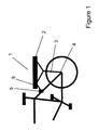
- a carrier (1) for a bicycle is shown attached over the rear wheel of a bicycle.
- the bicycle carrier (1) comprises a carrier top (2), which can either be used as it appears in the figure as a simple bicycle carrier (1), or it can be integrated with further components which are described in detail below.
- Attached to this carrier top (2) in a removable manner are one or more supporting members (3) which extend from the carrier top (2) to mounting points (4) provided on the cycle frame for supporting the carrier (1) and load.
- the mounting points (4) are positioned in the close vicinity of the rear axle of the bicycle, as is shown in figure 1, and are designed to be fixed to the bicycle and left in place when the carrier (1) is not being used.
- the mounting points (4) will be fixed to the frame of the bicycle using either a screw or a nut and bolt arrangement, utilising an eyelet in the bicycle frame provided for the connection of cycle carriers. Should no such connection point exist, it is a straightforward matter to drill a hole of suitable size in the frame of the bicycle, at the point which extends around the rear wheel axle to fix the wheel to the frame. It is further possible, that the mounting point (4) be integrated with the axle of the rear wheel, and be positioned around the axle between the hub of the rear wheel and the inner side of the frame.
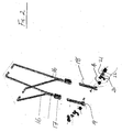
- the rear mounting points (4) provide a pin for interacting with the lower end of the supporting members (3), this is best seen in figure 2.
- the lower end of the supporting members (3) are provided with slots (19) which are designed to accommodate the pin of the mounting points (4).
- the mounting points (4) can be provided by mushroom connectors.
- mushroom connectors are cylindrical in shape, and are provided with a bore which extends through the central axis of the connector to be used for fixing to the bicycle.
- the outer surface of the connector varies in diameter along its length in a step wise manner, so that at either end of the connector the diameter is greater than in the middle. This, therefore, provides a connector which has an "H" profile, wherein the slots (19) at the end of the supporting members (3) are designed to fit within the region of reduced diameter and thereby be prevented from slipping off the mounting point (4).
- a front connector (5) which is positioned at a point forward of the mounting points (4).
- This front fixing point is designed and provided to stop rotation of the carrier (1) around the rear axle mounting points (4).
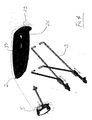
- the front connector (5) can be most clearly seen in figure 3, which shows an expanded view of the key components of the connector (5).
- this front connector (5) is intended to be semi-permanently fitted to the frame of the cycle, and left in place when the rest of the carrier (1) has been removed.
- Shown in figure 3 are two brackets (6) which are provided to fix the front connector (5) to carrier fixing points provided on the rear wheel forks of most cycles.
- L-shaped brackets Shown in the diagram are L-shaped brackets, although it is to be understood that the brackets (6) are not limited to these, and can be changed for simple plate brackets depending upon the fixing points on the cycle.
- the fixing brackets (6) are adjustably attached to the front connector (5) to accommodate a variety of widths in the bicycle side fixing points.
- two slots (7) are provided passing through the body of the front connector (5) through which bolts (8) are passed for engaging with the fixing brackets (6) at the desired spacing.
- the carrier (1) is attached to the front connector (5) by means of an adjustable securing rod (9).
- This rod (9) is fixable at one end to the carrier top (2) in a removable and adjustable manner, so that the carrier can be used with a variety of bicycle designs and shapes.
- the securing rod (9) either engages with one of a plurality of fixing points which allow it to be rotationally secured, or with a track which runs along the length of the carrier top (2) to which the rod (9) is clamped, again allowing for rotation of the rod (9) to accommodate different cycle frame designs.
- the securing rod (9) is engaged with the front connector (5) via a bore (10), which passes through the body of the connector (5).
- This bore (10) passes through the connector (5) in a direction which is substantially perpendicular to that between the carrier (1) and the front connector (5). In this manner, it is only required for the rod (9) to be bent into a configuration that will allow one end to slide into the bore (10) with the other being attached to the carrier top (2), so as to fully secure the carrier (1) and stop it from rotating around the rear axle mounting points (4).
- this locking mechanism is in the form of a button (11), which is biased by means of a spring (12).
- the actual locking mechanism is formed by a plate (13) which has 2 right angle bends in it, wherein the two opposing faces of this plate (13) are positioned within the connector and cross the path of the bore (10). Two holes are provided in these opposing faces in appropriate positions, so that when the plate (13) is fully engaged within the front connector (5) these holes align with the bore (10). Under the influence of the spring (12), however, the plate (13) is pushed out of the connector (5) body, and the holes on the plate become misaligned with the bore (10).
- the front connector further includes a safety strap (15).
- This strap (15) is attached to the front connector (5) via the bolts (8), and is designed to pass around the back of the frame of the bicycle to which the connector (5) is attached. In this way, should the fixing mechanism holding the front connector (5) to the frame fail, the front connector (5) will still remain fixed to the frame and will not allow the carrier (1) to rotate or become unattached.
- this safety strap (15) connected through the bolts (8) used for adjusting the width of the fixing brackets (6) any other method of securing the strap (15) to the front connector (5) around the frame is believed as being considered obvious by the skilled man and falling within the scope of the design.
- the strap (15) could be attached to the connector (5), and when the connector (5) is fixed to the frame the strap (15) is passed around the frame and the two ends are connected together, by means of a buckle or a clip, for instance.
- a modification to the design of the fixing rod (9), includes it having multiple bends.
- This design is particularly useful, as it further allows for the carrier (1) to be fastened to a wider range of cycles.
- the rod (9) in fashioned is such a manner, that the direction of the central axis at each end of the rod (9) lies perpendicular to each other, which therefore allows one end to fasten to the carrier top (2) with the other being engaged in the front connector (5).
- these two axes do not lie in the same plane as each other and are separated by a chosen distance. In this manner, when the rod (9) is inserted into the bore (10) of the front connector (5), by choosing which side to insert from, the height of the rod (9) can be adjusted.
- This adjustment is designed to allow for different frame designs, wherein the relationship between the front connector (5) frame attachment points and the height of the carrier top (2) above the rear wheel differs.
- the length of the supporting members (3) attached to the carrier top (2) can be varied. This is most simply achieved by the system as shown in figure 2.
- two sets of rods (16) are shown which extend from the carrier top (2) to a height adjusting block (17), to be held within. Whilst the diagram shows four rods grouped in pairs, it is to be understood that this is by way of example only, and that more or fewer can be used if so required. Furthermore, whilst it is envisioned that these rods be made from aluminium for both lightness and strength, it is clearly possible to fabricate them out of a different metal or indeed a rigid plastic.
- the rods (16) are designed to interact with the carrier top (2) and fasten thereto in a removable manner, and are shown in the figures attached to the underside of the top (2). Other designs, however, which fulfil the same function are clearly possible, and that shown in the figure is intended as one possible solution.
- the height plate (18) comprises a rigid plate of metal which has a series of holes spaced out along its length, such that when the slot (19) is in position around the rear mounting point (4) the holes extend in an upward direction.
- the height adjusting block (17) is possessed of a slot which is sized to accept the height plate (18); further, the block (17) is provided with a fixing pin which engages with the desired hole, and thus positions the adjusting block (17) at the desired height.
- the clip (20) can be rotated from its open position allowing access to the slot (19) to the closed position, wherein it passes under the rear mount (4) and stops the height plate (18) from disengaging as a result of the motion of the cycle.
- a spring (21) it is possible to bias this clip (20) by means of a spring (21), thereby ensuring that the clip is always engaged with the rear mounting point (4), and as such increasing the security of the locking mechanism.
- a protective cap (22) can be provided to cover the clip (20) and spring (21).
- the above disclosed arrangement for attaching the carrier (1) to a cycle means that one carrier (1) can be used with a range of cycles. This is particularly desirable when multiple users, say within a family, wish to use just one carrier (1). Provision of multiple front connectors (5) and rear axle mounts (4) attached to several cycles, in addition to the above disclosed adjustable support members (3) and securing rod (9), leads to a carrier (1) which can readily be moved from one cycle to another.
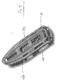
- Figure 4 is an exploded diagram detailing how the carrier top (2), the front connector (5) and the supporting members (3) are disposed to make the basis of the carrier (1).
- the preferred number of supporting members (3) each of which comprises a pair of rods (16) is two, that is: one either side of the rear wheel.
- the carrier top (2) is one half of a dovetail joint (23), for the secure connection of further carrier elements as detailed below.
- Shown in figure 4, is a carrier top (2) which is fully formed as a single unit, preferably out of a rigid plastic material, in which the half dovetail joint (23) is positioned toward the outer edge of the top (2).
- FIG. 5 Another possible method of providing one half of a joint for attachment of further carrier elements, is shown in figure 5, wherein a rigid wire (24) is situated above the carrier top (2) upper surface in a loop.
- This rigid wire loop (24) provides a fixing point which can be treated as one half of a dovetail joint, as in the case where the carrier top (2) is formulated from a single unit.
- the loop can also be used for attaching items to the carrier in the same way as the slots (25), which can be seen in figures 4 and 5, passing through the carrier top (2), securing the items by means of straps, rope, string or the like.
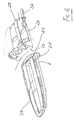
- the half dovetail joint in the carrier top (23), is specifically intended for interfacing the carrier top (2) with further elements of the carrier (1); figure 6 shows one such element in the form of a seat base (26).
- This seat base (26) is designed such that its underside has a half dovetail joint (27) which is the matching half of the carrier top dovetail joint (23).
- Attachment of the seat base (26) to the carrier (1) is by the simple sliding of the seat base (26) over the carrier top (2) such that the two halves of the joint engage.
- the carrier top (2) has a wire loop for the attachment of the seat base (26)
- the seat base (26) slides over this for attachment.
- the carrier top (2) Whilst the figures show the carrier top (2) being possessed of the tenon to the joint, in the case of the wire loop carrier (24) the seat base (26) has the mortise which slides over and around the loop, it is equally possible for these to be reversed. In this situation, the carrier top (2) has a dovetail shaped recess into which a tenon on the seat base (26) can slide; the wire loop carrier (24) is adapted so that the seat base tenon slides between the two sides of the loop to engage therewith.
- the dovetail joint between the carrier top (2, 24) and seat base (26) clearly stops the two elements from disengaging vertically, but there remains the possibility of the base (26) sliding off from the carrier (2).
- the seat base (26) can be fitted with at least one hand operable locking mechanism.
- Two solutions for this locking system are presented: a mechanism for causing the two halves of the dovetail joint to be gripped together so as to remove any play from the joint and stop the sliding disengagement; and a rotatable safety lock (28) which is connected to the seat base (26), and has projections that extend below the bottom of the seat base (26) to interact with the carrier top (2, 24). It is conceived that one or both of the above locking systems be fitted to the carrier (1) of the present invention, although with a well fitting dovetail joint (23, 27) it is possible that neither would be necessary.
- the wedges (29) are oriented so that the narrow portions face each other, and when they are pulled together by the biasing springs (30), thicker and thicker portions are introduced into the gap between the two halves of the joint and thus it is pushed apart and more securely held.
- a cam wheel (31) is mounted within the seat base (26) such when it is rotated, it acts upon linear extensions of the wedges (29) and pushes them apart.
- This cam wheel is provided with a grip and is intended to be hand operated.
- the cam wheel (31) must be in the position that forces the two wedges (29) apart for mounting or removal of the seat base (26) onto the carrier top (2). As the wedges act upon the carrier top (2), this method is particularly suited to the solid carrier top (2), rather than the wire loop top (24).
- this base (26) is formed from a piece of plastic in the shape of a "U"; that is, it has two extending arms which are separated by a small gap.
- the seat base (26) is positioned in the carrier top dovetail joint (23), these two arms are either squeezed together or pushed apart by hand operated means and therefore secure the dovetail joint.
- Shown in figure 6 is a locking lever (32), which has an extension passing through one of the seat base (26) arms to be secured in the other.
- This design is appropriate for when the carrier top (2) has the tenon of the dovetail joint, whether provided in the moulded plastic carrier top (2) or the carrier top possessing the rod loop (24), and the seat base (26) the mortise.
- lever (32) has an eccentric mounting point at one end of the extension, when it is rotated it acts upon the side of the seat base (26) and pushes the first arm toward the second, and in so doing grips the carrier top tenon (23). Whilst in the figure a lever (32) is shown, it is clear that other systems exist, such as a hand operated screw thread, which upon rotation pushes the two arms of the seat base (26) together. Additionally, in the system which employs a wire loop carrier top (24), it is possible to bias the rods outward so as to engage more tightly with the mortise of the seat base (26) and so secure the joint. This could be achieved by means of a hand operated screw thread, which upon rotation acts to force the rods apart.
- Figure 6 shows the relative positioning of the safety lock (28), if present, within the seat base (26) for further ensuring that it does not accidentally disengage from the carrier top (2, 24).
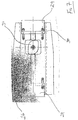
- Figure 8 shows a cross section through the engaged carrier top (2) and seat base (26) taken along the line A-A in figure 6.
- the projection from the safety lock (28) which extends below the bottom surface of the seat base (26) to engage with a resilient side of a recess (33) in the carrier top (2). This recess (33) can be more clearly seen in figure 6.
- the safety lock (28) rotates around the pivot point (34) and the projection end rises out of the dovetail joint region, until the recess (33) is reached.
- the projection drops down to engage the locking mechanism and prevents the seat base (26) from sliding back and disengaging from the carrier top (2). Whilst it is possible to allow this lock to work under the force of gravity alone, it is preferable to spring bias the rotation of the member to ensure that the lock (28) properly engages, and further prevent the motion of the cycle from bouncing it out of position.
- Figure 9 shows the seat base (26) of figure 6 with additional elements of the seat for integration with the carrier (1).
- the seat base (26) is possessed of a series of projections (35) extending upward at one end of the base (26).
- these projections (35) are formed such that they are positioned at the front of the carrier (1) when it is fixed to the cycle, although this is not necessary.
- These projections (35) provide one half of a rotatable hinge for integration of further seat elements, such as the cradle (36) shown in figure 9.
- Through the projections (35) in the seat base (26) are a series of holes (37) which each align along a central axis in a direction perpendicular to the direction of motion of the cycle.
- the underside of the cradle (36) is provided with a second set of projections (38) with holes (39) through.
- the two sets of projections (35, 38) are so designed as to interdigitate with each other such that the sets of holes (37, 39) align and with insertion of a split pin (40) form a hinge.
- This pin (40) can be formed in many ways, as two halves of a single pin (40) which after insertion into the holes (37, 39) are joined together; or as two shorter pins (40) which fit through half of the interdigitated projections (35, 38) only, and which form into the hinge in this manner. If the two separate pin (40) option is utilised, the inserted end is provided with a deformable section which after insertion through the holes (37, 39), stops the accidental removal of the pin (40) from the hinge.
- the cradle (36) has formed shoulders (41) which match the contour of the seat base projections (35). These shoulders (41) are positioned around the seat base projections (35) and will only allow the cradle (36) to rotate so far away from the seat base (26).
- the cradle unit (40) is provided with attachment points on its upper surface which are used for attachment of further carrier elements.
- Such elements could be, but are not limited to, a child's seat (42) or other carrying units, such as a box.
- suspension blocks (43) can be placed between the rotateably interconnected seat base (26) and cradle (36).
- These suspension blocks (43) are preferably made from rubber, as this is a naturally deforming substance with long durability, however, any appropriate elastomeric substance could be used.
- the positioning of these blocks (43) with respect to the hinge point can be altered so as to adjust the suspension effect.
- suspension blocks (43) are either held within specific fixing points provided on the top surface of the seat base (26) and corresponding points on the lower surface of the cradle (36), or a fixing track is provided on each of these carrier elements so as to allow the positioning of the block in a range of places to give a truly variable suspension effect.
- the spindle (44) shown has a screw thread which is in threaded engagement with a nut (45); this nut (45) being held within the cradle (36).
- a hand operated grip for rotation of the thread to adjust the position of the spindle (44) with respect to the nut (45), with the other end of the spindle (44) resting on the seat base (26).
- a further requirement of the spindle (44), is to integrate with the further elements which are attached to the cradle (36), be these the child's seat (42), storage boxes or the like.
- the hand operated end of the spindle (44) is required to be accessible when the further elements are attached, whilst additionally not getting in the way of the functioning of the elements.
- a further function that the spindle can perform, is to provide another fixing point between the seat (42) or storage element, and the cradle (36). In order to achieve this, the spindle is housed within the seat (42) or storage element, such that it can be rotated to allow adjustment of the suspension, whilst still connecting the element to the cradle (36).
Landscapes
- Engineering & Computer Science (AREA)
- Mechanical Engineering (AREA)
- Fittings On The Vehicle Exterior For Carrying Loads, And Devices For Holding Or Mounting Articles (AREA)
- Connection Of Plates (AREA)
- Manipulator (AREA)
- Handcart (AREA)
- Vehicle Step Arrangements And Article Storage (AREA)
- Accommodation For Nursing Or Treatment Tables (AREA)
- Gyroscopes (AREA)
- Automatic Cycles, And Cycles In General (AREA)
- Clamps And Clips (AREA)
Priority Applications (13)
| Application Number | Priority Date | Filing Date | Title |
|---|---|---|---|
| PL05006609T PL1705109T3 (pl) | 2005-03-24 | 2005-03-24 | Bagażnik rowerowy |
| AT05006609T ATE451293T1 (de) | 2005-03-24 | 2005-03-24 | Gepäckträger für fahrräder |
| EP05006609A EP1705109B1 (fr) | 2005-03-24 | 2005-03-24 | Portebagage pour bicyclette |
| DE602005018160T DE602005018160D1 (de) | 2005-03-24 | 2005-03-24 | Gepäckträger für Fahrräder |
| DK05006609.1T DK1705109T3 (da) | 2005-03-24 | 2005-03-24 | Bagagebærer til en cykel |
| EP08157590A EP1958857B1 (fr) | 2005-03-24 | 2006-03-23 | Embase de montage |
| PCT/IB2006/000666 WO2006100579A1 (fr) | 2005-03-24 | 2006-03-23 | Porte-bagages pour velo |
| EP08157573A EP1958856B1 (fr) | 2005-03-24 | 2006-03-23 | Dessus de porte-bagages |
| US11/576,680 US20090159626A1 (en) | 2005-03-24 | 2006-03-23 | Carrier rack for a bicycle |
| PT08157573T PT1958856E (pt) | 2005-03-24 | 2006-03-23 | ¿parte superior de porta-bagagem |
| EP06727355A EP1877297A1 (fr) | 2005-03-24 | 2006-03-23 | Portebagage pour bicyclette |
| AT08157590T ATE513731T1 (de) | 2005-03-24 | 2006-03-23 | Aufbauplatte |
| AT08157573T ATE509822T1 (de) | 2005-03-24 | 2006-03-23 | Aufsatz für einen gepäckträger |
Applications Claiming Priority (1)
| Application Number | Priority Date | Filing Date | Title |
|---|---|---|---|
| EP05006609A EP1705109B1 (fr) | 2005-03-24 | 2005-03-24 | Portebagage pour bicyclette |
Publications (2)
| Publication Number | Publication Date |
|---|---|
| EP1705109A1 true EP1705109A1 (fr) | 2006-09-27 |
| EP1705109B1 EP1705109B1 (fr) | 2009-12-09 |
Family
ID=35455887
Family Applications (4)
| Application Number | Title | Priority Date | Filing Date |
|---|---|---|---|
| EP05006609A Expired - Lifetime EP1705109B1 (fr) | 2005-03-24 | 2005-03-24 | Portebagage pour bicyclette |
| EP08157590A Expired - Lifetime EP1958857B1 (fr) | 2005-03-24 | 2006-03-23 | Embase de montage |
| EP06727355A Withdrawn EP1877297A1 (fr) | 2005-03-24 | 2006-03-23 | Portebagage pour bicyclette |
| EP08157573A Expired - Lifetime EP1958856B1 (fr) | 2005-03-24 | 2006-03-23 | Dessus de porte-bagages |
Family Applications After (3)
| Application Number | Title | Priority Date | Filing Date |
|---|---|---|---|
| EP08157590A Expired - Lifetime EP1958857B1 (fr) | 2005-03-24 | 2006-03-23 | Embase de montage |
| EP06727355A Withdrawn EP1877297A1 (fr) | 2005-03-24 | 2006-03-23 | Portebagage pour bicyclette |
| EP08157573A Expired - Lifetime EP1958856B1 (fr) | 2005-03-24 | 2006-03-23 | Dessus de porte-bagages |
Country Status (8)
| Country | Link |
|---|---|
| US (1) | US20090159626A1 (fr) |
| EP (4) | EP1705109B1 (fr) |
| AT (3) | ATE451293T1 (fr) |
| DE (1) | DE602005018160D1 (fr) |
| DK (1) | DK1705109T3 (fr) |
| PL (1) | PL1705109T3 (fr) |
| PT (1) | PT1958856E (fr) |
| WO (1) | WO2006100579A1 (fr) |
Cited By (3)
| Publication number | Priority date | Publication date | Assignee | Title |
|---|---|---|---|---|
| EP2275332A1 (fr) * | 2009-07-16 | 2011-01-19 | Hamax As | Adaptateur de sac |
| US10513299B2 (en) | 2017-10-08 | 2019-12-24 | Henry Gordon MacMorran | Adjustable bicycle rack |
| EP3854666A1 (fr) * | 2020-01-27 | 2021-07-28 | Curana Invest bvba | Assemblage de deux composants de bicyclette mutuellement connectables |
Families Citing this family (8)
| Publication number | Priority date | Publication date | Assignee | Title |
|---|---|---|---|---|
| WO2011028449A2 (fr) | 2009-08-24 | 2011-03-10 | Arkel Inc. | Râtelier autoporteur pour vélo |
| CN103958270B (zh) | 2011-05-25 | 2016-05-04 | 施拉奇锁有限责任公司 | 用于运输装置的锁安装组件 |
| US9079626B2 (en) | 2011-05-25 | 2015-07-14 | Robert David Zuraski | Portable lock mounting assemblies |
| US9302725B2 (en) * | 2013-03-14 | 2016-04-05 | Bell Sports, Inc. | Locking rack system for bicycles |
| US9694867B2 (en) * | 2013-03-14 | 2017-07-04 | Bell Sports, Inc. | Locking rack system for bicycles |
| US11535331B2 (en) * | 2017-08-30 | 2022-12-27 | Dongguan Hong Lin Industrial Co., Ltd | Bicycle mounting mechanism and battery box assembly |
| CN112158284B (zh) * | 2020-10-19 | 2021-11-02 | 无锡如森电动车有限公司 | 一种电动车用承载基板机构 |
| TWI791398B (zh) * | 2022-04-14 | 2023-02-01 | 鄭寧元大 | 置物架結構 |
Citations (4)
| Publication number | Priority date | Publication date | Assignee | Title |
|---|---|---|---|---|
| US4350361A (en) * | 1979-12-06 | 1982-09-21 | Chiaki Fujii | Load carrying platform for a bicycle |
| US4666071A (en) * | 1986-01-24 | 1987-05-19 | Cannondale Corporation | Bicycle rear carrier rack |
| DE4339761C1 (de) * | 1993-11-22 | 1995-04-13 | Wolfgang Weger | Gepäckträger für Zwei- oder Mehrräder, insbesondere Fahrräder |
| US5803329A (en) | 1995-04-24 | 1998-09-08 | Gebruder Pletscher Ag | Carrier rack for a two-wheeled vehicle, in particular for a bicycle |
Family Cites Families (27)
| Publication number | Priority date | Publication date | Assignee | Title |
|---|---|---|---|---|
| US1963333A (en) * | 1932-02-13 | 1934-06-19 | Mormye Inc | Carrier |
| US4053091A (en) * | 1976-05-28 | 1977-10-11 | Sears, Roebuck And Co. | Combination rear luggage carrier and child seat for bicycle |
| US4030648A (en) * | 1976-09-20 | 1977-06-21 | The Firestone Tire & Rubber Company | Carrier support apparatus |
| US4562944A (en) * | 1979-02-01 | 1986-01-07 | Eclipse, Inc. | Adjustable connections on cycle rear carrier |
| US4353490A (en) * | 1979-10-24 | 1982-10-12 | Jackson W S | Pannier mounting system for cycles |
| US4266703A (en) * | 1980-01-28 | 1981-05-12 | Reuben Litz | Slide mount for motorcycle luggage box |
| US4440331A (en) * | 1981-12-03 | 1984-04-03 | Schimmels Kristin L | Protective child carrier assembly |
| JPS58145271U (ja) * | 1982-03-26 | 1983-09-30 | 川崎重工業株式会社 | 自動2輪車用物品収納箱取付装置 |
| US5299818A (en) * | 1989-09-29 | 1994-04-05 | Bell Sports, Inc. | Child's bicycle seat and rack assembly |
| US5244132A (en) * | 1991-06-06 | 1993-09-14 | Lisa Christen | Garment bag and support rack therefor for use with bicycle |
| US5411190A (en) * | 1991-09-06 | 1995-05-02 | Aug. Winkhaus Gmbh & Co. Kg | Luggage carrier for a two-wheeled vehicle |
| US5257727A (en) * | 1992-06-26 | 1993-11-02 | Chen Ming Y | Luggage carrier for bicycles |
| DE9402459U1 (de) * | 1994-02-15 | 1994-04-07 | Gerda GmbH & Co, 58332 Schwelm | Behälter zur lösbaren Befestigung an Gepäckträgern von Fahrzeugen |
| DE9411316U1 (de) * | 1994-07-13 | 1994-09-08 | Kramer-Massow, Klaus, 79299 Wittnau | Verstellbarer Gepäckträger für Fahrräder mit und ohne Hinterradfederung |
| DE4434542A1 (de) * | 1994-09-28 | 1996-04-04 | Rixen & Kaul Gmbh | Pritsche für einen Gepäckträger und Zubehör, speziell Drahtkorb |
| US5575443A (en) * | 1994-10-04 | 1996-11-19 | Honeycutt; Jay W. | Quick release accessory mount on a bicycle |
| DE9417254U1 (de) * | 1994-10-27 | 1995-02-23 | Hinterberger, Norbert, 20148 Hamburg | Fahrrad- und Kraftradgepäckträger- Schienenschnappschloß- Koppelung |
| US5577646A (en) * | 1995-02-06 | 1996-11-26 | White; Richard D. | Pet carrier for bicycle |
| DE19717570C2 (de) * | 1997-04-25 | 2003-01-16 | Louis Chuang | Gepäckhaltevorrichtung für Fahrräder |
| IT1292411B1 (it) * | 1997-06-24 | 1999-02-08 | Giuseppe Visenzi | Supporto per contenitori in generale e valigie ventiquattrore in particolare,adatto per motocicli e simili |
| CH692498A5 (de) * | 1998-01-29 | 2002-07-15 | Pletscher Geb | Lasttragkörper für einen Gepäckträger. |
| DE29819331U1 (de) * | 1998-10-29 | 1999-01-28 | Chun Yeh Enterprise Co., Ltd., Tiee Shang, Taichung | Befestigungsvorrichtung für einen Aufbewahrungsbehälter |
| JP2001354178A (ja) * | 2000-06-14 | 2001-12-25 | Ogk Co Ltd | 車用バスケットの装着構造 |
| US6659547B2 (en) * | 2000-07-28 | 2003-12-09 | David R. Petersen | Adjustable back rest and cargo carrier for a motorcycle |
| AU2002364091A1 (en) * | 2001-12-20 | 2004-07-22 | Transbike Systems, Inc. | Attachment system for bicycle accessories |
| AR042631A1 (es) * | 2003-12-19 | 2005-06-29 | Kuo Jen Lee | Porta equipaje y traba con cerradura antirrobo desmontable para vehiculos de dos ruedas |
| US20060138185A1 (en) * | 2004-12-27 | 2006-06-29 | Chien-Ping Lien | Single-piece instantly detachable locking device with a board for traveling bag on bicycle carrier |
-
2005
- 2005-03-24 PL PL05006609T patent/PL1705109T3/pl unknown
- 2005-03-24 EP EP05006609A patent/EP1705109B1/fr not_active Expired - Lifetime
- 2005-03-24 DE DE602005018160T patent/DE602005018160D1/de not_active Expired - Lifetime
- 2005-03-24 AT AT05006609T patent/ATE451293T1/de active
- 2005-03-24 DK DK05006609.1T patent/DK1705109T3/da active
-
2006
- 2006-03-23 EP EP08157590A patent/EP1958857B1/fr not_active Expired - Lifetime
- 2006-03-23 AT AT08157573T patent/ATE509822T1/de not_active IP Right Cessation
- 2006-03-23 AT AT08157590T patent/ATE513731T1/de not_active IP Right Cessation
- 2006-03-23 EP EP06727355A patent/EP1877297A1/fr not_active Withdrawn
- 2006-03-23 PT PT08157573T patent/PT1958856E/pt unknown
- 2006-03-23 WO PCT/IB2006/000666 patent/WO2006100579A1/fr not_active Ceased
- 2006-03-23 EP EP08157573A patent/EP1958856B1/fr not_active Expired - Lifetime
- 2006-03-23 US US11/576,680 patent/US20090159626A1/en not_active Abandoned
Patent Citations (4)
| Publication number | Priority date | Publication date | Assignee | Title |
|---|---|---|---|---|
| US4350361A (en) * | 1979-12-06 | 1982-09-21 | Chiaki Fujii | Load carrying platform for a bicycle |
| US4666071A (en) * | 1986-01-24 | 1987-05-19 | Cannondale Corporation | Bicycle rear carrier rack |
| DE4339761C1 (de) * | 1993-11-22 | 1995-04-13 | Wolfgang Weger | Gepäckträger für Zwei- oder Mehrräder, insbesondere Fahrräder |
| US5803329A (en) | 1995-04-24 | 1998-09-08 | Gebruder Pletscher Ag | Carrier rack for a two-wheeled vehicle, in particular for a bicycle |
Cited By (4)
| Publication number | Priority date | Publication date | Assignee | Title |
|---|---|---|---|---|
| EP2275332A1 (fr) * | 2009-07-16 | 2011-01-19 | Hamax As | Adaptateur de sac |
| US10513299B2 (en) | 2017-10-08 | 2019-12-24 | Henry Gordon MacMorran | Adjustable bicycle rack |
| EP3854666A1 (fr) * | 2020-01-27 | 2021-07-28 | Curana Invest bvba | Assemblage de deux composants de bicyclette mutuellement connectables |
| BE1028014B1 (nl) * | 2020-01-27 | 2021-08-24 | Curana Invest Bv | Samenstel van twee met elkaar verbindbare fietsonderdelen |
Also Published As
| Publication number | Publication date |
|---|---|
| ATE451293T1 (de) | 2009-12-15 |
| EP1958856B1 (fr) | 2011-05-18 |
| PL1705109T3 (pl) | 2010-07-30 |
| ATE513731T1 (de) | 2011-07-15 |
| ATE509822T1 (de) | 2011-06-15 |
| US20090159626A1 (en) | 2009-06-25 |
| EP1705109B1 (fr) | 2009-12-09 |
| DK1705109T3 (da) | 2010-04-12 |
| EP1877297A1 (fr) | 2008-01-16 |
| DE602005018160D1 (de) | 2010-01-21 |
| PT1958856E (pt) | 2011-07-18 |
| EP1958856A3 (fr) | 2009-09-30 |
| EP1958857A2 (fr) | 2008-08-20 |
| EP1958856A2 (fr) | 2008-08-20 |
| WO2006100579A1 (fr) | 2006-09-28 |
| EP1958857A3 (fr) | 2009-10-07 |
| EP1958857B1 (fr) | 2011-06-22 |
| WO2006100579A8 (fr) | 2008-04-17 |
Similar Documents
| Publication | Publication Date | Title |
|---|---|---|
| US10124740B2 (en) | Bike carrier with automatic tray position lock | |
| US10808741B2 (en) | Quick-release clamp with secondary retention mechanism | |
| EP1705109B1 (fr) | Portebagage pour bicyclette | |
| US10011237B1 (en) | Bike carrier pivot mechanism | |
| US9340247B2 (en) | Connection system for pannier and method | |
| US7090308B2 (en) | Axle assembly for mounting a wheel to a vehicle | |
| EP2470415B1 (fr) | Râtelier autoporteur pour vélo | |
| US7431391B2 (en) | Adjustment assembly for a bicycle seat | |
| EA014679B1 (ru) | Самофиксирующийся механизм | |
| EP1233885B1 (fr) | Dispositif porte-charge monte sur vehicule | |
| CA2471149A1 (fr) | Support pour fixation a une bicyclette | |
| US10654540B2 (en) | Cycle carrier structure | |
| EP3339150A1 (fr) | Dispositif de couplage magnétique | |
| US20210221298A1 (en) | Method and System for Carrying a Bicycle on a Vehicle | |
| US5551609A (en) | Bicycle rack with integral lock holder | |
| EP4124549B1 (fr) | Sac pouvant être fixé pour bicyclette | |
| US20050092798A1 (en) | Clamp and clamp attached article carrier | |
| WO2009050520A1 (fr) | Système de montage de sacoche | |
| US9561419B2 (en) | Bicycle trainer with a bicycle wheel holding fixture | |
| EP2117878A1 (fr) | Porte-bicyclette prêt à l'emploi | |
| CN219847284U (zh) | 折叠助行车 | |
| WO2026020246A1 (fr) | Guidon détachable et fourche avant pour bicyclettes compactables |
Legal Events
| Date | Code | Title | Description |
|---|---|---|---|
| PUAI | Public reference made under article 153(3) epc to a published international application that has entered the european phase |
Free format text: ORIGINAL CODE: 0009012 |
|
| AK | Designated contracting states |
Kind code of ref document: A1 Designated state(s): AT BE BG CH CY CZ DE DK EE ES FI FR GB GR HU IE IS IT LI LT LU MC NL PL PT RO SE SI SK TR |
|
| AX | Request for extension of the european patent |
Extension state: AL BA HR LV MK YU |
|
| 17P | Request for examination filed |
Effective date: 20070302 |
|
| AKX | Designation fees paid |
Designated state(s): AT BE BG CH CY CZ DE DK EE ES FI FR GB GR HU IE IS IT LI LT LU MC NL PL PT RO SE SI SK TR |
|
| GRAP | Despatch of communication of intention to grant a patent |
Free format text: ORIGINAL CODE: EPIDOSNIGR1 |
|
| GRAS | Grant fee paid |
Free format text: ORIGINAL CODE: EPIDOSNIGR3 |
|
| GRAA | (expected) grant |
Free format text: ORIGINAL CODE: 0009210 |
|
| AK | Designated contracting states |
Kind code of ref document: B1 Designated state(s): AT BE BG CH CY CZ DE DK EE ES FI FR GB GR HU IE IS IT LI LT LU MC NL PL PT RO SE SI SK TR |
|
| REG | Reference to a national code |
Ref country code: GB Ref legal event code: FG4D |
|
| REG | Reference to a national code |
Ref country code: CH Ref legal event code: EP |
|
| REG | Reference to a national code |
Ref country code: IE Ref legal event code: FG4D |
|
| REF | Corresponds to: |
Ref document number: 602005018160 Country of ref document: DE Date of ref document: 20100121 Kind code of ref document: P |
|
| REG | Reference to a national code |
Ref country code: CH Ref legal event code: NV Representative=s name: TROESCH SCHEIDEGGER WERNER AG |
|
| REG | Reference to a national code |
Ref country code: SE Ref legal event code: TRGR |
|
| REG | Reference to a national code |
Ref country code: NL Ref legal event code: T3 |
|
| REG | Reference to a national code |
Ref country code: DK Ref legal event code: T3 |
|
| PG25 | Lapsed in a contracting state [announced via postgrant information from national office to epo] |
Ref country code: LT Free format text: LAPSE BECAUSE OF FAILURE TO SUBMIT A TRANSLATION OF THE DESCRIPTION OR TO PAY THE FEE WITHIN THE PRESCRIBED TIME-LIMIT Effective date: 20091209 Ref country code: FI Free format text: LAPSE BECAUSE OF FAILURE TO SUBMIT A TRANSLATION OF THE DESCRIPTION OR TO PAY THE FEE WITHIN THE PRESCRIBED TIME-LIMIT Effective date: 20091209 |
|
| LTIE | Lt: invalidation of european patent or patent extension |
Effective date: 20091209 |
|
| PG25 | Lapsed in a contracting state [announced via postgrant information from national office to epo] |
Ref country code: SI Free format text: LAPSE BECAUSE OF FAILURE TO SUBMIT A TRANSLATION OF THE DESCRIPTION OR TO PAY THE FEE WITHIN THE PRESCRIBED TIME-LIMIT Effective date: 20091209 |
|
| PG25 | Lapsed in a contracting state [announced via postgrant information from national office to epo] |
Ref country code: PT Free format text: LAPSE BECAUSE OF FAILURE TO SUBMIT A TRANSLATION OF THE DESCRIPTION OR TO PAY THE FEE WITHIN THE PRESCRIBED TIME-LIMIT Effective date: 20100409 Ref country code: BG Free format text: LAPSE BECAUSE OF FAILURE TO SUBMIT A TRANSLATION OF THE DESCRIPTION OR TO PAY THE FEE WITHIN THE PRESCRIBED TIME-LIMIT Effective date: 20100309 Ref country code: IS Free format text: LAPSE BECAUSE OF FAILURE TO SUBMIT A TRANSLATION OF THE DESCRIPTION OR TO PAY THE FEE WITHIN THE PRESCRIBED TIME-LIMIT Effective date: 20100409 Ref country code: ES Free format text: LAPSE BECAUSE OF FAILURE TO SUBMIT A TRANSLATION OF THE DESCRIPTION OR TO PAY THE FEE WITHIN THE PRESCRIBED TIME-LIMIT Effective date: 20100320 Ref country code: RO Free format text: LAPSE BECAUSE OF FAILURE TO SUBMIT A TRANSLATION OF THE DESCRIPTION OR TO PAY THE FEE WITHIN THE PRESCRIBED TIME-LIMIT Effective date: 20091209 Ref country code: EE Free format text: LAPSE BECAUSE OF FAILURE TO SUBMIT A TRANSLATION OF THE DESCRIPTION OR TO PAY THE FEE WITHIN THE PRESCRIBED TIME-LIMIT Effective date: 20091209 |
|
| REG | Reference to a national code |
Ref country code: PL Ref legal event code: T3 |
|
| PG25 | Lapsed in a contracting state [announced via postgrant information from national office to epo] |
Ref country code: SK Free format text: LAPSE BECAUSE OF FAILURE TO SUBMIT A TRANSLATION OF THE DESCRIPTION OR TO PAY THE FEE WITHIN THE PRESCRIBED TIME-LIMIT Effective date: 20091209 |
|
| PLBE | No opposition filed within time limit |
Free format text: ORIGINAL CODE: 0009261 |
|
| STAA | Information on the status of an ep patent application or granted ep patent |
Free format text: STATUS: NO OPPOSITION FILED WITHIN TIME LIMIT |
|
| PG25 | Lapsed in a contracting state [announced via postgrant information from national office to epo] |
Ref country code: GR Free format text: LAPSE BECAUSE OF FAILURE TO SUBMIT A TRANSLATION OF THE DESCRIPTION OR TO PAY THE FEE WITHIN THE PRESCRIBED TIME-LIMIT Effective date: 20100310 Ref country code: CY Free format text: LAPSE BECAUSE OF FAILURE TO SUBMIT A TRANSLATION OF THE DESCRIPTION OR TO PAY THE FEE WITHIN THE PRESCRIBED TIME-LIMIT Effective date: 20091209 Ref country code: MC Free format text: LAPSE BECAUSE OF NON-PAYMENT OF DUE FEES Effective date: 20100331 |
|
| 26N | No opposition filed |
Effective date: 20100910 |
|
| PG25 | Lapsed in a contracting state [announced via postgrant information from national office to epo] |
Ref country code: IE Free format text: LAPSE BECAUSE OF NON-PAYMENT OF DUE FEES Effective date: 20100324 |
|
| PGFP | Annual fee paid to national office [announced via postgrant information from national office to epo] |
Ref country code: DK Payment date: 20110325 Year of fee payment: 7 |
|
| PGFP | Annual fee paid to national office [announced via postgrant information from national office to epo] |
Ref country code: NL Payment date: 20110330 Year of fee payment: 7 Ref country code: IT Payment date: 20110323 Year of fee payment: 7 Ref country code: CZ Payment date: 20110322 Year of fee payment: 7 Ref country code: AT Payment date: 20110325 Year of fee payment: 7 Ref country code: CH Payment date: 20110330 Year of fee payment: 7 Ref country code: SE Payment date: 20110329 Year of fee payment: 7 |
|
| PGFP | Annual fee paid to national office [announced via postgrant information from national office to epo] |
Ref country code: FR Payment date: 20110414 Year of fee payment: 7 Ref country code: GB Payment date: 20110331 Year of fee payment: 7 |
|
| REG | Reference to a national code |
Ref country code: DE Ref legal event code: R231 Ref document number: 602005018160 Country of ref document: DE |
|
| PGFP | Annual fee paid to national office [announced via postgrant information from national office to epo] |
Ref country code: BE Payment date: 20110419 Year of fee payment: 7 Ref country code: PL Payment date: 20110121 Year of fee payment: 7 |
|
| PGFP | Annual fee paid to national office [announced via postgrant information from national office to epo] |
Ref country code: DE Payment date: 20110530 Year of fee payment: 7 |
|
| PG25 | Lapsed in a contracting state [announced via postgrant information from national office to epo] |
Ref country code: DE Free format text: LAPSE BECAUSE OF THE APPLICANT RENOUNCES Effective date: 20110805 |
|
| PG25 | Lapsed in a contracting state [announced via postgrant information from national office to epo] |
Ref country code: LU Free format text: LAPSE BECAUSE OF NON-PAYMENT OF DUE FEES Effective date: 20100324 Ref country code: HU Free format text: LAPSE BECAUSE OF FAILURE TO SUBMIT A TRANSLATION OF THE DESCRIPTION OR TO PAY THE FEE WITHIN THE PRESCRIBED TIME-LIMIT Effective date: 20100610 |
|
| BERE | Be: lapsed |
Owner name: HAMAX AS Effective date: 20120331 |
|
| REG | Reference to a national code |
Ref country code: NL Ref legal event code: V1 Effective date: 20121001 |
|
| REG | Reference to a national code |
Ref country code: SE Ref legal event code: EUG |
|
| PG25 | Lapsed in a contracting state [announced via postgrant information from national office to epo] |
Ref country code: TR Free format text: LAPSE BECAUSE OF FAILURE TO SUBMIT A TRANSLATION OF THE DESCRIPTION OR TO PAY THE FEE WITHIN THE PRESCRIBED TIME-LIMIT Effective date: 20091209 Ref country code: SE Free format text: LAPSE BECAUSE OF NON-PAYMENT OF DUE FEES Effective date: 20120325 |
|
| REG | Reference to a national code |
Ref country code: CH Ref legal event code: PL |
|
| REG | Reference to a national code |
Ref country code: DK Ref legal event code: EBP |
|
| GBPC | Gb: european patent ceased through non-payment of renewal fee |
Effective date: 20120324 |
|
| REG | Reference to a national code |
Ref country code: AT Ref legal event code: MM01 Ref document number: 451293 Country of ref document: AT Kind code of ref document: T Effective date: 20120324 |
|
| REG | Reference to a national code |
Ref country code: FR Ref legal event code: ST Effective date: 20121130 |
|
| PG25 | Lapsed in a contracting state [announced via postgrant information from national office to epo] |
Ref country code: FR Free format text: LAPSE BECAUSE OF NON-PAYMENT OF DUE FEES Effective date: 20120402 Ref country code: BE Free format text: LAPSE BECAUSE OF NON-PAYMENT OF DUE FEES Effective date: 20120331 Ref country code: CH Free format text: LAPSE BECAUSE OF NON-PAYMENT OF DUE FEES Effective date: 20120331 Ref country code: AT Free format text: LAPSE BECAUSE OF NON-PAYMENT OF DUE FEES Effective date: 20120324 Ref country code: LI Free format text: LAPSE BECAUSE OF NON-PAYMENT OF DUE FEES Effective date: 20120331 Ref country code: GB Free format text: LAPSE BECAUSE OF NON-PAYMENT OF DUE FEES Effective date: 20120324 Ref country code: CZ Free format text: LAPSE BECAUSE OF NON-PAYMENT OF DUE FEES Effective date: 20120324 |
|
| PG25 | Lapsed in a contracting state [announced via postgrant information from national office to epo] |
Ref country code: IT Free format text: LAPSE BECAUSE OF NON-PAYMENT OF DUE FEES Effective date: 20120324 |
|
| PG25 | Lapsed in a contracting state [announced via postgrant information from national office to epo] |
Ref country code: NL Free format text: LAPSE BECAUSE OF NON-PAYMENT OF DUE FEES Effective date: 20121001 |
|
| PG25 | Lapsed in a contracting state [announced via postgrant information from national office to epo] |
Ref country code: DK Free format text: LAPSE BECAUSE OF NON-PAYMENT OF DUE FEES Effective date: 20120331 |
|
| PG25 | Lapsed in a contracting state [announced via postgrant information from national office to epo] |
Ref country code: PL Free format text: LAPSE BECAUSE OF NON-PAYMENT OF DUE FEES Effective date: 20120324 |
|
| REG | Reference to a national code |
Ref country code: PL Ref legal event code: LAPE |