EP1705111B1 - Verankerungsvorrichtung mit bewegbarem Ballast - Google Patents
Verankerungsvorrichtung mit bewegbarem Ballast Download PDFInfo
- Publication number
- EP1705111B1 EP1705111B1 EP06251452A EP06251452A EP1705111B1 EP 1705111 B1 EP1705111 B1 EP 1705111B1 EP 06251452 A EP06251452 A EP 06251452A EP 06251452 A EP06251452 A EP 06251452A EP 1705111 B1 EP1705111 B1 EP 1705111B1
- Authority
- EP
- European Patent Office
- Prior art keywords
- vessel
- arm
- mooring
- ballast weight
- mooring apparatus
- Prior art date
- Legal status (The legal status is an assumption and is not a legal conclusion. Google has not performed a legal analysis and makes no representation as to the accuracy of the status listed.)
- Expired - Lifetime
Links
Images
Classifications
-
- B—PERFORMING OPERATIONS; TRANSPORTING
- B63—SHIPS OR OTHER WATERBORNE VESSELS; RELATED EQUIPMENT
- B63B—SHIPS OR OTHER WATERBORNE VESSELS; EQUIPMENT FOR SHIPPING
- B63B21/00—Tying-up; Shifting, towing, or pushing equipment; Anchoring
- B63B21/50—Anchoring arrangements or methods for special vessels, e.g. for floating drilling platforms or dredgers
-
- B—PERFORMING OPERATIONS; TRANSPORTING
- B63—SHIPS OR OTHER WATERBORNE VESSELS; RELATED EQUIPMENT
- B63B—SHIPS OR OTHER WATERBORNE VESSELS; EQUIPMENT FOR SHIPPING
- B63B21/00—Tying-up; Shifting, towing, or pushing equipment; Anchoring
Definitions
- the present invention relates to apparatus for disconnectably mooring one vessel to another in a heavy seaway off shore.
- Such disconnectable moorings are frequently required, for example, in off-shore oil and gas fields, where a shuttle tanker needs to moor in close proximity to a permanently anchored storage tanker, in order to facilitate the transfer of oil or liquefied gases so that these may be transported away by the shuttle tanker.
- the present invention concerns tandem mooring, in which the two vessels are moored in line with each other, e.g. when the bow of the shuttle tanker approaches and is moored to the stern of the storage tanker.
- tandem moorings make use of so-called "soft yoke” technology, whereby the required restoring forces imposed on the shuttle tanker and the storage tanker are created by a submerged ballastable rigid arm or yoke and transferred to a articulated tether.
- Examples of such ballastable mooring systems can be found in NL 173254 and EP 0079404 .
- EP 0096119 discloses a single point mooring system in which a yoke pivoting in a loading buoy is provided with ballasts at the end of the arms.
- the present invention provides mooring apparatus for mooring first and second vessels together, comprising a rigid arm with a longitudinal axis and first and second ends, wherein the arm is mountable to a first vessel so that its longitudinal axis is substantially parallel to the longitudinal axis of the vessel and so as to be rotatable about a substantially horizontal pivot axis substantially perpendicular to the longitudinal axis and located between the first and second ends, a tension member pivotally mounted to the second end of the arm and connectable in use to a second vessel; a ballast weight moveably mounted on the arm, drive means operable to move the ballast weight longitudinally along the arm and actuation means pivotally mounted to the first end of the arm operable to control rotation of the arm about the pivot axis.
- Provision of a moveable ballast weight in this way allows the second vessel to be connected to the apparatus with relatively small connecting loads, but once connected, prevents the yoke masses being excited due to motions of the storage tanker.
- the tension member includes buoyancy means. This allows the tension member to float in a substantially vertical position with its upper end at the waterline in order to facilitate its connection to the second vessel.
- the actuation means is operable to cause rotation of the arm about the pivot axis in one direction and to act as damping means to restrain uncontrolled rotation of the arm in the opposite direction. In this way, it can be used to locate the arm in the optimal position for different operations and will restrain free-fall of the arm when it is disconnected from a second vessel.
- the actuation means will comprise a piston pivotally mounted to the arm and slidably received in a hydraulic cylinder which is pivotally mountable to the first vessel. It is also preferable if the actuation means includes stop means to limit extension of the piston.
- the present invention also provides a floating vessel incorporating a mooring apparatus of the aforementioned type and fluid transfer means connectable to a second vessel for transfer of fluid between the two.
- the apparatus will be connected to the stern of the first vessel, and extend aft of the vessel.
- the present invention also provides a method for mooring first and second vessels together using the aforementioned apparatus.
- the method comprises the steps of providing a first vessel with the mooring apparatus, locating the ballast weight close to, but outboard of, the pivot axis, operating the actuation means to pivot the arm about the pivot axis such that the second end of the arm is lower than the first end, connecting a flexible member between the second vessel and the tension member, using the flexible member to pull the second vessel towards the first vessel until the tension member can be directly connected to the second vessel and subsequently moving the ballast weight longitudinally to the second end of the arm.
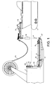
- a vessel such as a storage tanker 1, which may be may be permanently anchored, is fitted with a structural framework consisting of an arm or yoke 2 extending aft of the vessel.
- the yoke 2 is preferably submerged and located between the keel and the waterline of the storage tanker 1.
- the yoke 2 is a generally A-shaped frame, which is free to pivot about a nominally horizontal axis 3 located a short distance aft of the main body of the vessel 1.
- a tether 4 is pivotally mounted.
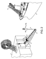
- This may be a substantially rigid elongate member, or a flexible member such as a chain or cable, provided with buoyancy means 16 at the free end remote from the yoke 2. In this way it remains substantially vertical, with the buoyancy means 16 floating close to or at the waterline when no shuttle tanker is moored to it, as shown in Figure 2.
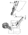
- the upper end 5 of the tether 4 can be disconnectably fitted to an outrigger 6 of another vessel such as a shuttle tanker 7 in use, as seen in Figures 1 and 3.
- the outrigger 6 is preferably pivotably mounted on the shuttle tanker 7 so that it can rotate about axis 14 in order to lie fully within the confines of the vessel's upper deck when in transit, as shown in Figure 2, and only be moved into its outwardly extending position when required.
- a ballast weight 8 is provided on the yoke 2, lying substantially on a central longitudinal axis 17 of the yoke 2 perpendicular to the pivot axis 3.
- the ballast weight 8 is moveable back and forth along the axis by any suitable powered drive mechanism 9.
- the yoke 2 At its inboard end i.e. closest to the vessel 1, the yoke 2 is connected to a rod 10 which extends upwards and is slidable through a sleeve 11 which is pivotally mounted to the vessel 1 for rotation about a nominally horizontal axis 18.
- a hydraulic jack system 12 is fitted to the sleeve 11. This serves as a free fall damping means for the end of the yoke 2 (as discussed further below) and engages against a stopper plate 13 fixed on the rod 10 at a pre-determined position below the sleeve 11.
- the yoke 2 In the condition shown in Figure 2, before the shuttle tanker 7 is moored, the yoke 2 extends downwardly away from the vessel 1. However, the hydraulic system 12 can also be extended to push rod 10 downwardly, thereby causing yoke 2 to pivot around the axis 3. This lowers its inboard end and raises its outboard end to bring it into a nominally horizontal position. This may be useful for example during transit of the vessel from its building yard or for maintenance purposes.
- a fluid transfer system 15 is provided for transferring fluid from the storage tanker 1 to the shuttle tanker 7.
- This may take any convenient shape and form, and typically will consist of multiple articulated steel or flexible pipelines with quick connect and disconnect devices.
- the ballast weight 8 is located just outboard of the pivot axis 3.
- the hydraulic system 12 maintains the yoke 2 in its downwardly tilted position so that it is below the keel of the approaching shuttle tanker 7 to avoid any collision risk.
- the tether 4 extends upwardly with its buoyancy means 16 floating roughly at the waterline.
- the ballast weight 8 is close to the pivot axis 3, the load on the wire rope 19 is relatively low. Furthermore the hydraulic system 12 cannot exert tension forces on the tether 4, and so the shuttle tanker 7 can connect the upper end 5 of the tether 4 to its outrigger 6 without restraint.
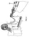
- the ballast weight 8 is moved further outboard towards the end of the yoke 2. This increases the tension in the tether 4 to the required level for station keeping of the shuttle tanker 7. In addition, motions of the storage tanker 1 do not lead to excitation of the yoke 2 masses, due to the ballast 8.
- an improved mooring system which allows for a relatively quick and easy connection procedure and which avoids the masses of the yoke structure being excited by movement of the storage tanker.
Landscapes
- Chemical & Material Sciences (AREA)
- Engineering & Computer Science (AREA)
- Combustion & Propulsion (AREA)
- Mechanical Engineering (AREA)
- Ocean & Marine Engineering (AREA)
- Loading And Unloading Of Fuel Tanks Or Ships (AREA)
- Physical Water Treatments (AREA)
- Filling Or Discharging Of Gas Storage Vessels (AREA)
- Arrangement Of Elements, Cooling, Sealing, Or The Like Of Lighting Devices (AREA)
- Circuit Arrangements For Discharge Lamps (AREA)
- Transmission Devices (AREA)
- Foundations (AREA)
Claims (8)
- Festmachvorrichtung zum Festmachen eines ersten Schiffs an einem zweiten Schiff, umfassend:einen starren Arm (2) mit einer Längsachse (17) und einem ersten und einem zweiten Ende, wobei der Arm (2) an einem ersten Schiff (1) angebracht werden kann, so dass seine Längsachse (17) im Wesentlichen parallel zu der Längsachse des Schiffs (1) ist und so dass er um eine im Wesentlichen horizontale Schwenkachse (3) schwenkbar ist, welche im Wesentlichen orthogonal zu der Längsachse ist und zwischen dem ersten und dem zweiten Ende angeordnet ist;ein Spannelement (4), welches schwenkbar an dem zweiten Ende des Arms (2) angebracht ist und bei der Verwendung mit einem zweiten Schiff (7) verbunden werden kann;ein beweglich an dem Arm (2) angebrachtes Gegengewicht (8);Antriebsmittel (9), welche betreibbar sind, um das Gegengewicht (8) in Längsrichtung entlang des Arms (2) zu bewegen;und schwenkbar an dem ersten Ende des Arms (2) angebrachte Antriebsmittel (10-13), welche betreibbar sind, um das Schwenken des Arms (2) um die Schwenkachse (3) zu steuern.
- Festmachvorrichtung nach Anspruch 1, wobei das Spannelement (4) Auftriebsmittel (16) umfasst.
- Festmachervorrichtung nach Anspruch 1 oder Anspruch 2, wobei das Antriebsmittel (10-13) betreibbar ist, um ein Schwenken des Arms (2) um die Schwenkachse (3) in eine Richtung zu bewirken und um als Dämpfungsmittel zu wirken, um ein ungesteuertes Schwenken in die entgegengesetzte Richtung zu verhindern.
- Festmachvorrichtung nach Anspruch 3, wobei das Antriebsmittel (10-13) einen Kolben (12) umfasst, der schwenkbar an dem Arm (2) angebracht ist und verschiebbar in einem schwenkbar an dem ersten Schiff (1) angebrachten Hydraulikzylinder angebracht ist.
- Festmachvorrichtung nach Anspruch 4, welche ferner Anschlagmittel (13) umfasst, um eine Ausdehnung des Kolbens (12) zu begrenzen.
- Schwimmendes Schiff (1) mit einer Festmachvorrichtung nach einem der vorangehenden Ansprüche, welches ferner Fluidübertragungsmittel (15) umfasst, die mit einem zweiten Schiff (7) verbunden werden können, um Fluid zu diesem zu übertragen.
- Schwimmendes Schiff nach Anspruch 6, wobei die Festmachvorrichtung mit dem Heck des ersten Schiffs (1) verbunden ist und sich von diesem nach achtern erstreckt.
- Verfahren zum Festmachen eines ersten Schiffs (1) an einem zweiten Schiff (7), umfassend die folgenden Schritte: Versehen des ersten Schiffs (1) mit einer Festmachvorrichtung nach einem der Ansprüche 1 bis 5; Anordnen des Gegengewichts (8) in der Nähe von, aber außenbords der Schwenkachse (3); Betreiben des Antriebsmittels (10-13) zum Schwenken des Arms (2) um die Schwenkachse (3) derart, dass sich das zweite Ende des Arms (2) unterhalb des ersten Endes befindet; Anbringen eines flexiblen Elements (19) zwischen dem zweiten Schiff (7) und dem Spannelement (4); Verwenden des flexiblen Elements (19), um das zweite Schiff (7) zu dem ersten Schiff (1) zu ziehen, bis das Spannelement direkt mit dem zweiten Schiff (7) verbunden werden kann; und Bewegen des Gegengewichts (8) in Längsrichtung zu dem zweiten Ende des Arms (8).
Applications Claiming Priority (1)
| Application Number | Priority Date | Filing Date | Title |
|---|---|---|---|
| GB0505759A GB2424404B (en) | 2005-03-21 | 2005-03-21 | Mooring apparatus with moveable ballast weight |
Publications (2)
| Publication Number | Publication Date |
|---|---|
| EP1705111A1 EP1705111A1 (de) | 2006-09-27 |
| EP1705111B1 true EP1705111B1 (de) | 2007-08-01 |
Family
ID=34531590
Family Applications (1)
| Application Number | Title | Priority Date | Filing Date |
|---|---|---|---|
| EP06251452A Expired - Lifetime EP1705111B1 (de) | 2005-03-21 | 2006-03-17 | Verankerungsvorrichtung mit bewegbarem Ballast |
Country Status (6)
| Country | Link |
|---|---|
| US (1) | US7322308B2 (de) |
| EP (1) | EP1705111B1 (de) |
| AT (1) | ATE368610T1 (de) |
| DE (1) | DE602006000052D1 (de) |
| ES (1) | ES2290945T3 (de) |
| GB (1) | GB2424404B (de) |
Cited By (1)
| Publication number | Priority date | Publication date | Assignee | Title |
|---|---|---|---|---|
| US8381669B2 (en) | 2007-03-20 | 2013-02-26 | Statoilhydro Asa | System for loading of hydrocarbons from a floating vessel |
Families Citing this family (13)
| Publication number | Priority date | Publication date | Assignee | Title |
|---|---|---|---|---|
| GB2436497B8 (en) * | 2003-04-10 | 2007-12-17 | Vik Sandvik As | Method for loading/unloading a support vessel at an offshore installation. |
| KR20070085870A (ko) * | 2004-11-08 | 2007-08-27 | 쉘 인터내셔날 리써취 마트샤피지 비.브이. | 액화천연가스 부유식 저장 재기화 설비 |
| US20100326667A1 (en) * | 2009-04-24 | 2010-12-30 | Ton Coppens | Production of hydrocarbons |
| BR112013003208B1 (pt) * | 2010-08-13 | 2022-03-29 | Horton Do Brasil Technologia Offshore, Ltda. | Sistema para descarga de um fluido de uma estrutura de armazenamento de fluido marítima e método para descarregar um fluido de uma estrutura de armazenamento de fluido marítima em um navio-tanque. |
| FR2968058B1 (fr) * | 2010-11-30 | 2012-12-28 | Saipem Sa | Support en mer equipe d'un dispositif de stockage et de guidage de conduites flexibles utiles pour le transfert en mer de produits petroliers |
| FR2967990B1 (fr) * | 2010-11-30 | 2014-11-28 | Saipem Sa | Support installe en mer equipe d'un dispositif de connexion et de vannes utile pour la purge de conduites flexibles |
| GB201103413D0 (en) * | 2011-03-01 | 2011-04-13 | Techflow Marine Ltd | Improvements in or relating to hose loading stations |
| BR102013001316B1 (pt) * | 2013-01-18 | 2021-11-03 | Altave Industria, Comercio E Exportação De Aeronaves Ltda-me | Dispositivo de ancoragem de aeróstatos |
| CN103482024B (zh) * | 2013-08-26 | 2016-05-18 | 上海利策海洋工程技术有限公司 | 轻型单点系泊外输出装置 |
| CN104671185A (zh) * | 2013-11-26 | 2015-06-03 | 湖北华舟重工应急装备股份有限公司 | 一种海底输油通道 |
| CN104709445B (zh) * | 2014-12-15 | 2017-01-11 | 中国海洋石油总公司 | 一种非单点系泊海上原油储存设施的外输装置 |
| US11738828B2 (en) | 2021-10-08 | 2023-08-29 | Sofec, Inc. | Disconnectable yoke mooring systems and processes for using same |
| CN118119549A (zh) | 2021-10-08 | 2024-05-31 | 索菲克股份有限公司 | 可断开的叉臂系泊系统及其使用方法 |
Family Cites Families (15)
| Publication number | Priority date | Publication date | Assignee | Title |
|---|---|---|---|---|
| US4099542A (en) * | 1976-06-09 | 1978-07-11 | Fmc Corporation | Marine loading arm jumper assembly |
| FR2367654A1 (fr) | 1976-10-15 | 1978-05-12 | Emh | Perfectionnements apportes aux sy |
| US4393906A (en) * | 1979-10-01 | 1983-07-19 | Fmc Corporation | Stern to bow offshore loading system |
| US4310277A (en) * | 1980-03-10 | 1982-01-12 | Robinson James S | Apparatus for transferring cargo between relatively movable bodies |
| FR2487807B1 (fr) * | 1980-08-04 | 1985-11-15 | Fmc Europe | Procede et agencement hydromecanique permettant, notamment, le degagement d'un bras articule de transfert de produits fluides, en deconnexion d'urgence |
| EP0096119B2 (de) * | 1982-06-11 | 1992-07-22 | Bluewater Terminal Systems N.V. | Einpunktbefestigungs-System mit starrem Arm für schwimmende Fahrzeuge |
| EP0105976A1 (de) * | 1982-10-15 | 1984-04-25 | Bluewater Terminal Systems N.V. | Einpunktverankerungseinrichtung mit starrem Arm |
| US4530302A (en) * | 1983-03-25 | 1985-07-23 | Sofec, Inc. | Submerged single point mooring apparatus |
| NL8602526A (nl) * | 1986-10-08 | 1988-05-02 | Single Buoy Moorings | Werkeiland, dat door middel van op trek belaste spanorganen is verankerd en is voorzien van middelen voor het afmeren van een schip. |
| NO981332L (no) | 1998-03-24 | 1999-09-27 | Hitec Marine As | System for offshore lasting av kalde medier |
| EP0947464A1 (de) | 1998-04-01 | 1999-10-06 | Single Buoy Moorings Inc. | Ladeausleger für Flüssigkeiten mit koaxialen Flüssigkeitsleitungen |
| WO2001051345A1 (en) * | 2000-01-07 | 2001-07-19 | Fmc Corporation | Mooring systems with active force reacting systems and passive damping |
| EP1283159A1 (de) * | 2001-08-06 | 2003-02-12 | Single Buoy Moorings Inc. | Übergabesystem für Kohlenwasserstoffe |
| AU2003217986A1 (en) * | 2002-03-08 | 2003-09-22 | Fmc Technologies, Inc. | Disconnectable mooring system and lng transfer system and method |
| AU2003287647A1 (en) * | 2002-11-12 | 2004-06-03 | Fmc Technologies, Inc. | Retrieval and connection system for a disconnectable mooring yoke |
-
2005
- 2005-03-21 GB GB0505759A patent/GB2424404B/en not_active Expired - Fee Related
-
2006
- 2006-03-17 EP EP06251452A patent/EP1705111B1/de not_active Expired - Lifetime
- 2006-03-17 DE DE602006000052T patent/DE602006000052D1/de not_active Expired - Lifetime
- 2006-03-17 AT AT06251452T patent/ATE368610T1/de not_active IP Right Cessation
- 2006-03-17 ES ES06251452T patent/ES2290945T3/es not_active Expired - Lifetime
- 2006-03-21 US US11/385,088 patent/US7322308B2/en active Active
Cited By (1)
| Publication number | Priority date | Publication date | Assignee | Title |
|---|---|---|---|---|
| US8381669B2 (en) | 2007-03-20 | 2013-02-26 | Statoilhydro Asa | System for loading of hydrocarbons from a floating vessel |
Also Published As
| Publication number | Publication date |
|---|---|
| ES2290945T3 (es) | 2008-02-16 |
| EP1705111A1 (de) | 2006-09-27 |
| ATE368610T1 (de) | 2007-08-15 |
| US7322308B2 (en) | 2008-01-29 |
| GB2424404A (en) | 2006-09-27 |
| GB2424404B (en) | 2007-02-28 |
| US20060207487A1 (en) | 2006-09-21 |
| DE602006000052D1 (de) | 2007-09-13 |
| GB0505759D0 (en) | 2005-04-27 |
Similar Documents
| Publication | Publication Date | Title |
|---|---|---|
| EP1705111B1 (de) | Verankerungsvorrichtung mit bewegbarem Ballast | |
| EP1462358B1 (de) | Verankerungsvorrichtung geeignet für ein Flüssiggas-Transportschiff | |
| US20130291779A1 (en) | Apparatus to launch and recover a boat | |
| US5339760A (en) | Apparatus for securing a vessel to a submersible mooring buoy | |
| US5501625A (en) | Floating terminal | |
| US6923598B2 (en) | Method and apparatus for the lifting of offshore installation jackets | |
| CN105151239A (zh) | 用于双船浮托整体拆除海上平台上部组块的船侧支撑结构 | |
| US20180319467A1 (en) | Device and method for securing a watercraft | |
| EP3601141A1 (de) | Hebevorrichtung | |
| AU2005317295B2 (en) | Soft quay mooring system | |
| CN101057042B (zh) | 软码头锚泊系统 | |
| JPS5992291A (ja) | タンカ−の係留および荷積荷卸装置ならびにその設置方法 | |
| US8156884B2 (en) | Vessel mooring systems and methods | |
| US20240253743A1 (en) | Mooring assembly | |
| US6619223B2 (en) | Tender with hawser lines | |
| KR101842665B1 (ko) | 신축 가능한 체인 연결 장치 | |
| US7182660B2 (en) | Offshore fluid transfer system | |
| NO159006B (no) | Fremgangsmaate og anordning til heving eller dokksetting av halvt nedsenkbare rigger. | |
| CN85106607A (zh) | 重力基座水下铰接单点系泊装置 | |
| CN218877518U (zh) | 一种适应低潮位的滚装舷侧跳板 | |
| GB2383317A (en) | Submerged friction mooring device | |
| JPS59179487A (ja) | 一点係船装置 |
Legal Events
| Date | Code | Title | Description |
|---|---|---|---|
| PUAI | Public reference made under article 153(3) epc to a published international application that has entered the european phase |
Free format text: ORIGINAL CODE: 0009012 |
|
| AK | Designated contracting states |
Kind code of ref document: A1 Designated state(s): AT BE BG CH CY CZ DE DK EE ES FI FR GB GR HU IE IS IT LI LT LU LV MC NL PL PT RO SE SI SK TR |
|
| AX | Request for extension of the european patent |
Extension state: AL BA HR MK YU |
|
| 17P | Request for examination filed |
Effective date: 20061017 |
|
| 17Q | First examination report despatched |
Effective date: 20061117 |
|
| GRAP | Despatch of communication of intention to grant a patent |
Free format text: ORIGINAL CODE: EPIDOSNIGR1 |
|
| AKX | Designation fees paid |
Designated state(s): AT BE BG CH CY CZ DE DK EE ES FI FR GR HU IE IS IT LI LT LU LV MC NL PL PT RO SE SI SK TR |
|
| GRAS | Grant fee paid |
Free format text: ORIGINAL CODE: EPIDOSNIGR3 |
|
| GRAA | (expected) grant |
Free format text: ORIGINAL CODE: 0009210 |
|
| AK | Designated contracting states |
Kind code of ref document: B1 Designated state(s): AT BE BG CH CY CZ DE DK EE ES FI FR GR HU IE IS IT LI LT LU LV MC NL PL PT RO SE SI SK TR |
|
| REG | Reference to a national code |
Ref country code: CH Ref legal event code: EP |
|
| REG | Reference to a national code |
Ref country code: IE Ref legal event code: FG4D |
|
| REF | Corresponds to: |
Ref document number: 602006000052 Country of ref document: DE Date of ref document: 20070913 Kind code of ref document: P |
|
| ET | Fr: translation filed | ||
| PG25 | Lapsed in a contracting state [announced via postgrant information from national office to epo] |
Ref country code: LT Free format text: LAPSE BECAUSE OF FAILURE TO SUBMIT A TRANSLATION OF THE DESCRIPTION OR TO PAY THE FEE WITHIN THE PRESCRIBED TIME-LIMIT Effective date: 20070801 Ref country code: IS Free format text: LAPSE BECAUSE OF FAILURE TO SUBMIT A TRANSLATION OF THE DESCRIPTION OR TO PAY THE FEE WITHIN THE PRESCRIBED TIME-LIMIT Effective date: 20071201 Ref country code: BG Free format text: LAPSE BECAUSE OF FAILURE TO SUBMIT A TRANSLATION OF THE DESCRIPTION OR TO PAY THE FEE WITHIN THE PRESCRIBED TIME-LIMIT Effective date: 20071101 Ref country code: FI Free format text: LAPSE BECAUSE OF FAILURE TO SUBMIT A TRANSLATION OF THE DESCRIPTION OR TO PAY THE FEE WITHIN THE PRESCRIBED TIME-LIMIT Effective date: 20070801 |
|
| REG | Reference to a national code |
Ref country code: CH Ref legal event code: PL |
|
| REG | Reference to a national code |
Ref country code: ES Ref legal event code: FG2A Ref document number: 2290945 Country of ref document: ES Kind code of ref document: T3 |
|
| PG25 | Lapsed in a contracting state [announced via postgrant information from national office to epo] |
Ref country code: PL Free format text: LAPSE BECAUSE OF FAILURE TO SUBMIT A TRANSLATION OF THE DESCRIPTION OR TO PAY THE FEE WITHIN THE PRESCRIBED TIME-LIMIT Effective date: 20070801 Ref country code: CH Free format text: LAPSE BECAUSE OF FAILURE TO SUBMIT A TRANSLATION OF THE DESCRIPTION OR TO PAY THE FEE WITHIN THE PRESCRIBED TIME-LIMIT Effective date: 20070801 Ref country code: LI Free format text: LAPSE BECAUSE OF FAILURE TO SUBMIT A TRANSLATION OF THE DESCRIPTION OR TO PAY THE FEE WITHIN THE PRESCRIBED TIME-LIMIT Effective date: 20070801 Ref country code: AT Free format text: LAPSE BECAUSE OF FAILURE TO SUBMIT A TRANSLATION OF THE DESCRIPTION OR TO PAY THE FEE WITHIN THE PRESCRIBED TIME-LIMIT Effective date: 20070801 |
|
| PG25 | Lapsed in a contracting state [announced via postgrant information from national office to epo] |
Ref country code: LV Free format text: LAPSE BECAUSE OF FAILURE TO SUBMIT A TRANSLATION OF THE DESCRIPTION OR TO PAY THE FEE WITHIN THE PRESCRIBED TIME-LIMIT Effective date: 20070801 Ref country code: BE Free format text: LAPSE BECAUSE OF FAILURE TO SUBMIT A TRANSLATION OF THE DESCRIPTION OR TO PAY THE FEE WITHIN THE PRESCRIBED TIME-LIMIT Effective date: 20070801 |
|
| PG25 | Lapsed in a contracting state [announced via postgrant information from national office to epo] |
Ref country code: DK Free format text: LAPSE BECAUSE OF FAILURE TO SUBMIT A TRANSLATION OF THE DESCRIPTION OR TO PAY THE FEE WITHIN THE PRESCRIBED TIME-LIMIT Effective date: 20070801 Ref country code: GR Free format text: LAPSE BECAUSE OF FAILURE TO SUBMIT A TRANSLATION OF THE DESCRIPTION OR TO PAY THE FEE WITHIN THE PRESCRIBED TIME-LIMIT Effective date: 20071102 |
|
| PG25 | Lapsed in a contracting state [announced via postgrant information from national office to epo] |
Ref country code: SK Free format text: LAPSE BECAUSE OF FAILURE TO SUBMIT A TRANSLATION OF THE DESCRIPTION OR TO PAY THE FEE WITHIN THE PRESCRIBED TIME-LIMIT Effective date: 20070801 Ref country code: CZ Free format text: LAPSE BECAUSE OF FAILURE TO SUBMIT A TRANSLATION OF THE DESCRIPTION OR TO PAY THE FEE WITHIN THE PRESCRIBED TIME-LIMIT Effective date: 20070801 Ref country code: PT Free format text: LAPSE BECAUSE OF FAILURE TO SUBMIT A TRANSLATION OF THE DESCRIPTION OR TO PAY THE FEE WITHIN THE PRESCRIBED TIME-LIMIT Effective date: 20080102 |
|
| PLBE | No opposition filed within time limit |
Free format text: ORIGINAL CODE: 0009261 |
|
| STAA | Information on the status of an ep patent application or granted ep patent |
Free format text: STATUS: NO OPPOSITION FILED WITHIN TIME LIMIT |
|
| PG25 | Lapsed in a contracting state [announced via postgrant information from national office to epo] |
Ref country code: SE Free format text: LAPSE BECAUSE OF FAILURE TO SUBMIT A TRANSLATION OF THE DESCRIPTION OR TO PAY THE FEE WITHIN THE PRESCRIBED TIME-LIMIT Effective date: 20071101 Ref country code: RO Free format text: LAPSE BECAUSE OF FAILURE TO SUBMIT A TRANSLATION OF THE DESCRIPTION OR TO PAY THE FEE WITHIN THE PRESCRIBED TIME-LIMIT Effective date: 20070801 |
|
| 26N | No opposition filed |
Effective date: 20080506 |
|
| PG25 | Lapsed in a contracting state [announced via postgrant information from national office to epo] |
Ref country code: DE Free format text: LAPSE BECAUSE OF FAILURE TO SUBMIT A TRANSLATION OF THE DESCRIPTION OR TO PAY THE FEE WITHIN THE PRESCRIBED TIME-LIMIT Effective date: 20071103 |
|
| PG25 | Lapsed in a contracting state [announced via postgrant information from national office to epo] |
Ref country code: MC Free format text: LAPSE BECAUSE OF NON-PAYMENT OF DUE FEES Effective date: 20080331 |
|
| PG25 | Lapsed in a contracting state [announced via postgrant information from national office to epo] |
Ref country code: IE Free format text: LAPSE BECAUSE OF NON-PAYMENT OF DUE FEES Effective date: 20080317 Ref country code: EE Free format text: LAPSE BECAUSE OF FAILURE TO SUBMIT A TRANSLATION OF THE DESCRIPTION OR TO PAY THE FEE WITHIN THE PRESCRIBED TIME-LIMIT Effective date: 20070801 |
|
| PG25 | Lapsed in a contracting state [announced via postgrant information from national office to epo] |
Ref country code: SI Free format text: LAPSE BECAUSE OF FAILURE TO SUBMIT A TRANSLATION OF THE DESCRIPTION OR TO PAY THE FEE WITHIN THE PRESCRIBED TIME-LIMIT Effective date: 20070801 |
|
| PG25 | Lapsed in a contracting state [announced via postgrant information from national office to epo] |
Ref country code: CY Free format text: LAPSE BECAUSE OF FAILURE TO SUBMIT A TRANSLATION OF THE DESCRIPTION OR TO PAY THE FEE WITHIN THE PRESCRIBED TIME-LIMIT Effective date: 20070801 |
|
| PG25 | Lapsed in a contracting state [announced via postgrant information from national office to epo] |
Ref country code: HU Free format text: LAPSE BECAUSE OF FAILURE TO SUBMIT A TRANSLATION OF THE DESCRIPTION OR TO PAY THE FEE WITHIN THE PRESCRIBED TIME-LIMIT Effective date: 20080202 Ref country code: LU Free format text: LAPSE BECAUSE OF NON-PAYMENT OF DUE FEES Effective date: 20080317 |
|
| PG25 | Lapsed in a contracting state [announced via postgrant information from national office to epo] |
Ref country code: TR Free format text: LAPSE BECAUSE OF FAILURE TO SUBMIT A TRANSLATION OF THE DESCRIPTION OR TO PAY THE FEE WITHIN THE PRESCRIBED TIME-LIMIT Effective date: 20070801 |
|
| REG | Reference to a national code |
Ref country code: FR Ref legal event code: PLFP Year of fee payment: 11 |
|
| PGFP | Annual fee paid to national office [announced via postgrant information from national office to epo] |
Ref country code: ES Payment date: 20160322 Year of fee payment: 11 Ref country code: NL Payment date: 20160318 Year of fee payment: 11 |
|
| PGFP | Annual fee paid to national office [announced via postgrant information from national office to epo] |
Ref country code: FR Payment date: 20160331 Year of fee payment: 11 Ref country code: IT Payment date: 20160322 Year of fee payment: 11 |
|
| REG | Reference to a national code |
Ref country code: NL Ref legal event code: MM Effective date: 20170401 |
|
| REG | Reference to a national code |
Ref country code: FR Ref legal event code: ST Effective date: 20171130 |
|
| PG25 | Lapsed in a contracting state [announced via postgrant information from national office to epo] |
Ref country code: NL Free format text: LAPSE BECAUSE OF NON-PAYMENT OF DUE FEES Effective date: 20170401 Ref country code: FR Free format text: LAPSE BECAUSE OF NON-PAYMENT OF DUE FEES Effective date: 20170331 |
|
| PG25 | Lapsed in a contracting state [announced via postgrant information from national office to epo] |
Ref country code: IT Free format text: LAPSE BECAUSE OF NON-PAYMENT OF DUE FEES Effective date: 20170317 |
|
| REG | Reference to a national code |
Ref country code: ES Ref legal event code: FD2A Effective date: 20180629 |
|
| PG25 | Lapsed in a contracting state [announced via postgrant information from national office to epo] |
Ref country code: ES Free format text: LAPSE BECAUSE OF NON-PAYMENT OF DUE FEES Effective date: 20170318 |