EP1705357B1 - Procédé et dispositif correspondant de diagnostic des ratés d'allumage ou conditions de combustion partielle dans un moteur à combustion interne - Google Patents
Procédé et dispositif correspondant de diagnostic des ratés d'allumage ou conditions de combustion partielle dans un moteur à combustion interne Download PDFInfo
- Publication number
- EP1705357B1 EP1705357B1 EP06110565A EP06110565A EP1705357B1 EP 1705357 B1 EP1705357 B1 EP 1705357B1 EP 06110565 A EP06110565 A EP 06110565A EP 06110565 A EP06110565 A EP 06110565A EP 1705357 B1 EP1705357 B1 EP 1705357B1
- Authority
- EP
- European Patent Office
- Prior art keywords
- engine
- misfire
- pressure
- condition
- clustering
- Prior art date
- Legal status (The legal status is an assumption and is not a legal conclusion. Google has not performed a legal analysis and makes no representation as to the accuracy of the status listed.)
- Expired - Lifetime
Links
Images



Classifications
-
- F—MECHANICAL ENGINEERING; LIGHTING; HEATING; WEAPONS; BLASTING
- F02—COMBUSTION ENGINES; HOT-GAS OR COMBUSTION-PRODUCT ENGINE PLANTS
- F02D—CONTROLLING COMBUSTION ENGINES
- F02D41/00—Electrical control of supply of combustible mixture or its constituents
- F02D41/24—Electrical control of supply of combustible mixture or its constituents characterised by the use of digital means
- F02D41/2406—Electrical control of supply of combustible mixture or its constituents characterised by the use of digital means using essentially read only memories
- F02D41/2425—Particular ways of programming the data
- F02D41/2429—Methods of calibrating or learning
- F02D41/2451—Methods of calibrating or learning characterised by what is learned or calibrated
- F02D41/2454—Learning of the air-fuel ratio control
-
- F—MECHANICAL ENGINEERING; LIGHTING; HEATING; WEAPONS; BLASTING
- F02—COMBUSTION ENGINES; HOT-GAS OR COMBUSTION-PRODUCT ENGINE PLANTS
- F02D—CONTROLLING COMBUSTION ENGINES
- F02D35/00—Controlling engines, dependent on conditions exterior or interior to engines, not otherwise provided for
- F02D35/02—Controlling engines, dependent on conditions exterior or interior to engines, not otherwise provided for on interior conditions
- F02D35/023—Controlling engines, dependent on conditions exterior or interior to engines, not otherwise provided for on interior conditions by determining the cylinder pressure
-
- F—MECHANICAL ENGINEERING; LIGHTING; HEATING; WEAPONS; BLASTING
- F02—COMBUSTION ENGINES; HOT-GAS OR COMBUSTION-PRODUCT ENGINE PLANTS
- F02D—CONTROLLING COMBUSTION ENGINES
- F02D41/00—Electrical control of supply of combustible mixture or its constituents
- F02D41/02—Circuit arrangements for generating control signals
- F02D41/14—Introducing closed-loop corrections
- F02D41/1401—Introducing closed-loop corrections characterised by the control or regulation method
-
- F—MECHANICAL ENGINEERING; LIGHTING; HEATING; WEAPONS; BLASTING
- F02—COMBUSTION ENGINES; HOT-GAS OR COMBUSTION-PRODUCT ENGINE PLANTS
- F02D—CONTROLLING COMBUSTION ENGINES
- F02D41/00—Electrical control of supply of combustible mixture or its constituents
- F02D41/02—Circuit arrangements for generating control signals
- F02D41/14—Introducing closed-loop corrections
- F02D41/1401—Introducing closed-loop corrections characterised by the control or regulation method
- F02D41/1405—Neural network control
-
- F—MECHANICAL ENGINEERING; LIGHTING; HEATING; WEAPONS; BLASTING
- F02—COMBUSTION ENGINES; HOT-GAS OR COMBUSTION-PRODUCT ENGINE PLANTS
- F02D—CONTROLLING COMBUSTION ENGINES
- F02D41/00—Electrical control of supply of combustible mixture or its constituents
- F02D41/02—Circuit arrangements for generating control signals
- F02D41/14—Introducing closed-loop corrections
- F02D41/1438—Introducing closed-loop corrections using means for determining characteristics of the combustion gases; Sensors therefor
- F02D41/1444—Introducing closed-loop corrections using means for determining characteristics of the combustion gases; Sensors therefor characterised by the characteristics of the combustion gases
- F02D41/1454—Introducing closed-loop corrections using means for determining characteristics of the combustion gases; Sensors therefor characterised by the characteristics of the combustion gases the characteristics being an oxygen content or concentration or the air-fuel ratio
- F02D41/1458—Introducing closed-loop corrections using means for determining characteristics of the combustion gases; Sensors therefor characterised by the characteristics of the combustion gases the characteristics being an oxygen content or concentration or the air-fuel ratio with determination means using an estimation
-
- G—PHYSICS
- G06—COMPUTING OR CALCULATING; COUNTING
- G06F—ELECTRIC DIGITAL DATA PROCESSING
- G06F18/00—Pattern recognition
- G06F18/20—Analysing
- G06F18/23—Clustering techniques
- G06F18/232—Non-hierarchical techniques
- G06F18/2321—Non-hierarchical techniques using statistics or function optimisation, e.g. modelling of probability density functions
- G06F18/23213—Non-hierarchical techniques using statistics or function optimisation, e.g. modelling of probability density functions with fixed number of clusters, e.g. K-means clustering
-
- F—MECHANICAL ENGINEERING; LIGHTING; HEATING; WEAPONS; BLASTING
- F02—COMBUSTION ENGINES; HOT-GAS OR COMBUSTION-PRODUCT ENGINE PLANTS
- F02D—CONTROLLING COMBUSTION ENGINES
- F02D41/00—Electrical control of supply of combustible mixture or its constituents
- F02D41/02—Circuit arrangements for generating control signals
- F02D41/14—Introducing closed-loop corrections
- F02D41/1401—Introducing closed-loop corrections characterised by the control or regulation method
- F02D2041/141—Introducing closed-loop corrections characterised by the control or regulation method using a feed-forward control element
-
- F—MECHANICAL ENGINEERING; LIGHTING; HEATING; WEAPONS; BLASTING
- F02—COMBUSTION ENGINES; HOT-GAS OR COMBUSTION-PRODUCT ENGINE PLANTS
- F02D—CONTROLLING COMBUSTION ENGINES
- F02D41/00—Electrical control of supply of combustible mixture or its constituents
- F02D41/02—Circuit arrangements for generating control signals
- F02D41/14—Introducing closed-loop corrections
- F02D41/1401—Introducing closed-loop corrections characterised by the control or regulation method
- F02D41/1404—Fuzzy logic control
-
- F—MECHANICAL ENGINEERING; LIGHTING; HEATING; WEAPONS; BLASTING
- F02—COMBUSTION ENGINES; HOT-GAS OR COMBUSTION-PRODUCT ENGINE PLANTS
- F02D—CONTROLLING COMBUSTION ENGINES
- F02D41/00—Electrical control of supply of combustible mixture or its constituents
- F02D41/02—Circuit arrangements for generating control signals
- F02D41/18—Circuit arrangements for generating control signals by measuring intake air flow
- F02D41/187—Circuit arrangements for generating control signals by measuring intake air flow using a hot wire flow sensor
Definitions
- This invention relates to internal combustion engines and more particularly to a method and a relative device for diagnosing misfire or partial combustion conditions in an internal combustion engine.
- a misfire condition (missed internal combustion) of internal combustion engines is generally due to the fact that fuel is not injected into the cylinder malfunctioning of the injector or the air/fuel mixture does not ignites because of malfunctioning of spark plugs, in spark ignition engines. Besides these misfire conditions, an incomplete (partial) combustion or lack of combustion may take place even for other causes, such as:
- Exhaust Gas Recirculation or more briefly EGR
- EGR exhaust Gas Recirculation
- load, engine speed and alkies actuates a variable opening of an exhaust gas recirculation valve and thus a different dilution of the air/fuel mixture.
- an excessive dilution of the injection mixture may favor the occurrence of partial combustion or misfire.
- Misfires in particular, besides depending engine performances and emissions of hydrocarbons, may damage the catalytic converter. Indeed, because of the high temperature in the catalytic converter (around 450°C), following a misfire the unburned mixture may ignite itself in the catalytic converter and damage it.
- Identifying and analyzing the causes that may lead to misfires and partial combustions in spark ignition engines is important in engine control systems.
- misfire conditions are diagnosed, in many engines, by using speed sensors installed close to the crankshaft for sensing the occurrence of misfires by detecting variations of the angular speed of the crankshaft.
- a misfire condition is diagnosed by measuring the time duration of pulses of a phonic wheel of the engine: misfire events cause an abrupt deceleration of the rotation of the crankshaft, and as a consequence they abruptly increase the duration between two successive pulses of the phonic wheel.
- This method of diagnosing a misfire condition has drawbacks due essentially to possible alterations of the motion unrelated to misfire conditions and limitations due to fabrication tolerances of the phonic wheel.
- a rough road on which a vehicle is running may influence the angular speed of its engine, and this is likely to cause spurious identification of misfires.
- An alternative and more effective method of diagnosing misfires is based on the analysis of the pressure signal in the combustion chamber.
- the pressure signal is acquired by using a pressure sensor installed directly in the combustion chamber. Diagnosing misfire conditions with this technique has innumerable advantages in respect to other techniques commonly implemented in the ECU of engines and based substantially on the analysis of the angular speed of the engine.
- the indicated mean effective pressure (or more briefly IMEP) is the parameter of the pressure cycle that is more frequently used for identifying misfire phenomena. In a cycle in which a misfire takes place, the IMEP is negative (and also the torque). Unfortunately, calculation of this parameter is onerous because the IMEP is proportional to the integral along the whole pressure-volume cycle of the pressure in respect to the volume.
- US 5,878,717 discloses a system and method for controlling an air-fuel ratio of an internal combustion engine using a ratio of cylinder pressures measured within at least one cylinder.
- the air-fuel ratio control system includes an electronic control module (ECM) which computes a measured cylinder pressure ratio of the cylinder pressure measured at a predetermined crank angle before top dead center and the cylinder pressure measured at a predetermined crank angle after top dead center. The measured cylinder pressure ratio is compared with an optimal cylinder pressure ratio. Based upon the results of this comparison, the ECM then determines an adjusted air-fuel ratio which would modify the measured pressure ratio to equal the optimal pressure ratio.
- ECM electronice control module
- JP 62030932 discloses a simple decision circuit for detecting the state of a misfire quickly and accurately, by detecting when the cylinder internal pressure at the upper dead point for a certain crank angle is almost equal to that at the position behind it by the same cranck angle therefrom.
- combustion conditions are discriminated with soft-computing techniques directly exploiting a combustion pressure signal generated by a common pressure sensor installed in the cylinder.
- the applicants have found that there exists an exploitably close correlation between the instantaneous values of the internal cylinder pressure and the occurrence of misfire or partial combustion conditions, and thus the cylinder pressure signal may be reliably used for diagnosing misfires or partial combustions in any functioning condition of the engine. Therefore, phonic wheels installed on the drive shaft are no longer required nor it is anymore necessary to disable the diagnosis unit when the vehicle is running on a rough road or during transient conditions.
- the diagnosis device of this invention is faster than the known devices because it is not necessary to calculate the IMEP parameter for identifying a misfire condition.
- the diagnosis device of this invention may be used for realizing a controller for an internal combustion engine.
- the method of this invention may even be carried out by a software code executed by a computer or by an ECU (Engine Control Unit).
- ECU Engine Control Unit
- a way of diagnosing a misfire condition by monitoring the pressure cycle consists in detecting the condition expressed by the following inequality: P ⁇ P ⁇ ⁇ ⁇ 1 wherein P is the pressure in the combustion chamber and ⁇ is the crank angle in respect to the position at which the TDC (Top Dead Center) normally occurs.
- P is the pressure in the combustion chamber
- ⁇ is the crank angle in respect to the position at which the TDC (Top Dead Center) normally occurs.
- the ratio P ( ⁇ )/ P (- ⁇ ) is monitored for diagnosing an occurred misfire or a condition of partial combustion. It has been found that when this ratio becomes larger than a pre-established threshold, it may be reliably assumed that a partial combustion is taking place in the cylinder and thus appropriate control actions may be carried out for correcting this undesired condition.
- Figure 1 depicts a block diagram of a feedback-and-feedforward control system of this invention of an internal combustion engine.
- This control system includes a feedforward controller A, a pressure sensor, a feedback controller B and the diagnosis unit C of this invention that generates a signal representative of a misfire condition or of a partial combustion condition by analyzing pressure signal generated by a pressure sensor installed in a combustion chamber of a cylinder of the engine.
- the feedforward controller A is input with signals representative of the speed and of the load of the engine, and outputs a signal DI, that establishes the duration of the fuel injection pulse and a spark generation control signal SA, that determines the spark-advance.
- the levels of these signals DI and SA are calculated by the feedforward controller A in function of the current speed and load of the engine using a pre-determined model of the engine (engine maps).
- the feedback controller B generates feedback signals DI* and SA* for correcting the calculated fuel injection duration and spark advance, represented by the signals DI and SA, respectively, in function of the signal generated by the diagnosis unit C of this invention.
- the feedback controller may generate a warning to the driver and then may even cut the fuel in order to avoid damages to the catalytic converter.
- the diagnosis unit C of this invention is substantially composed of a block C2 that generates signals representative of values of the ratio P ( ⁇ )/ P (- ⁇ ) by sampling the pressure signal P in correspondence of different crank angles ⁇ and of a block C1, that decides whether the engine is in a misfire condition or in a partial combustion condition or is functioning normally.
- This block generates the signals SA and DI in function of the speed and load of the engine by using control maps of the engine.
- a mathematical model of the functioning of the engine is determined during a test phase in order to determine, for any pair of values of speed and load of the engine, the best values of the duration of the fuel injection and the spark-advance of the engine.
- the feedforward controller A compares the input values of speed and load with those stored in a look-up table generated during a test phase of the engine, and outputs the signals DI and SA of corresponding values. When the input values of the speed and load do not correspond to any pair of the look-up table, the feedforward controller A calculates the levels of the signals DI and SA by linear interpolation.
- the calculated duration of fuel injection represented by the signal DI is corrected by a feedback signal DI* that is conditioned by a diagnostic signal, asserting a misfire, a partial combustion or a normal functioning condition of the engine.
- diagnosis unit C includes a subsystem C2 FEATURE SELECTOR that extract from the combustion pressure cycle at least an operation parameter sufficient for diagnosing the functioning of the engine.
- the subsystem C2 receives as input information the pressure signal generated by the pressure sensor fitted in at least a cylinder of the engine and generates from this signal the values of the pressure ratios P ( ⁇ i )/ P (- ⁇ i ) measured at predefined crank angles ⁇ i that, in a preliminary test phase, have been identified as discriminating among the different functioning conditions of the engine.
- the core C1 is, from a mathematical point of view, similar to a classifier that provides, in function of the ratios detected at different crank angles, a qualitative evaluation relative to the current combustion condition.
- the block C1 associates to the values of the above ratios a class indicating if the combustion process is normal (class 1) or if partial combustion (class 2) or misfire (class 3) events occurred.
- the core C1 of the diagnosis unit analyzes, during a certain number of pressure cycles, the values of the ratio P ( ⁇ )/ P (- ⁇ ) in correspondence of predefined crank angles.
- the n values of the pressure ratios measured in each pressure cycle identify a corresponding point of a n -dimensional space. The functioning of the engine is observed for a certain number of consecutive pressure cycles and a corresponding number of points are located.
- the number of clusters to be identified by the clustering algorithm is not greater than three.
- the best clustering of these points performed by the C1 block, that is the best number of clusters is determined by evaluating a clustering performance index as described in the cited prior European Patent application N° 05425121.0 .
- a brief introduction to clustering algorithms and to the clustering performance index is provided later.
- the core C1 executes the clustering algorithm, identifies the number of clusters that maximize the clustering performance index and decides whether, during the observed pressure cycles, only normal combustion conditions have occurred or not and the type of non normal combustion process that has occurred.
- clusters for which the arithmetic mean of the n components of their center of gravity is comprised between 0 and 1 correspond to misfire conditions
- clusters for which the arithmetic mean of the n components of their center of gravity is comprised between 1 and a pre-fixed threshold k represent normal functioning conditions
- clusters for which the arithmetic mean of the n components of their center of gravity is larger than k represent partial combustion conditions.
- the threshold k may be adjusted during a preliminary test phase of the engine.
- the core of diagnosis unit may either be a neural network, a fuzzy system or any other learning machine.
- Data sequence means data come from a temporal sampling, e.g. a signal temporal sampling, or also the temporal sequence of engine pressure cycles.
- data ensemble means data (in an M-dimensional space) that are not temporally linked.
- U ik elements are suitably linked to the distances of X points from c temporary cluster centers.
- M P 0 ⁇ U i ⁇ k ⁇ 1 ⁇ i , k ⁇ k ⁇ i
- M P M possibilistic
- U ik element is the possibility (typicality) that X k point belongs to the i -th sub-structure.
- M F M fuzzy
- U ik element corresponds to the membership probability of x k point to the i -th sub-structure; these probabilities satisfy for each k a normalization condition.
- the three matrices are related by the following relation: M crisp ⁇ M fuzzy ⁇ M possibilistic
- Finding the "optimal partition "of a data set X means to find the matrix U ik which better represents the unknown sub-structures of X in comparison to the clustering model that the algorithm induces.
- clustering algorithms are subdivided into two main groups: “hard” and “soft”.
- hard clustering algorithms each vector belongs only to a single cluster (that is clusters are disjoint), while in “soft” clustering algorithms each vector may belong to more clusters with different fuzzy degrees.
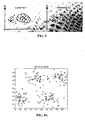
- Figure 3 shows a sample set of bi-dimensional data clustered in two different ways.
- a good clustering algorithm should identify the two clusters of the example CLUSTERING1.
- a satisfactory clustering algorithm for the objectives of this invention is the FCM (Fuzzy C-Means).
- FCM Fuzzy C-Means Algorithm
- the FCM algorithm is based on Fuzzy System Theory which is used as an invaluable mathematical tool in many application fields.
- a fuzzy set is an element set with a "blurred" membership concept.
- FCM is an iterative procedure based on the idea that clusters can be handled as fuzzy sets.
- U kj 1, ..., c
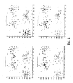
- Figures 4a and 4b depict a set of bi-dimensional data before clustering them and after having executed a FCM algorithm, respectively, that grouped them into four clusters.
- the FCM clustering model can be described as an optimization problem with constraints.
- m is the system fuzzyness degree while D ik matrix represents the distances between distribution points (x k ) and cluster centers (v i ).
- D ik matrix represents the distances between distribution points (x k ) and cluster centers (v i ).
- m 0 the fuzzy clusters become classical clusters, that is, each sample belongs only to a cluster.
- m 0 the system fuzzyness level grows. If m ⁇ ⁇ we can observe that the membership degrees of data set points approach to 1/ c and cluster centers approach to the distribution center.
- the FCM algorithm optimizes a criterion which is the "fuzzy" version of the "trace criterion" [2].
- the steps of the FCM algorithm may be summarized as follows:
- Step 2 Updating the centers of the clusters:
- Step 3 Updating the matrix of membership functions:
- Step 4 Stop condition:
- the above algorithm may be executed for several clustering strategies of data set X, that is, for different number of clusters (from c min to c max ) .
- the "optimal" number of clusters c opt is one minimizes the performance index P(c).
- P(c) has a minimum when data set clustering has a minimum intra-cluster variance (i.e. small values of D ik in e J ⁇ min ,(c)) and a maximum inter-cluster variance (i.e. maximum cluster center distances v i from data set centers x ⁇ ).
- a graph of the performance index versus the number of clusters may be plot.
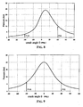
- Figure 7 shows that the best clustering performance index of the sample data of Figure 4a is obtained with four clusters.
Landscapes
- Engineering & Computer Science (AREA)
- General Engineering & Computer Science (AREA)
- Mechanical Engineering (AREA)
- Combustion & Propulsion (AREA)
- Chemical & Material Sciences (AREA)
- Data Mining & Analysis (AREA)
- Evolutionary Computation (AREA)
- Artificial Intelligence (AREA)
- Theoretical Computer Science (AREA)
- Physics & Mathematics (AREA)
- Computer Vision & Pattern Recognition (AREA)
- Evolutionary Biology (AREA)
- General Physics & Mathematics (AREA)
- Bioinformatics & Computational Biology (AREA)
- Bioinformatics & Cheminformatics (AREA)
- Life Sciences & Earth Sciences (AREA)
- Probability & Statistics with Applications (AREA)
- Combined Controls Of Internal Combustion Engines (AREA)
- Electrical Control Of Air Or Fuel Supplied To Internal-Combustion Engine (AREA)
Claims (6)
- Procédé pour diagnostiquer un état de raté d'allumage ou de combustion partielle dans un moteur à explosion, comprenant les étapes suivantes :détecter la pression dans au moins un cylindre du moteur et produire un signal de pression ;extraire du signal de pression produit au moins la valeur instantanée du rapport

où P est la pression dans la chambre de combustion du cylindre et θ est la position angulaire du moteur par rapport au point mort haut, pour des positions angulaires préétablies ;caractérisé en ce que le procédé comprend les étapes suivantes :regrouper des ensembles de valeurs dudit rapport dans un certain nombre de groupes en traitant les ensembles par un algorithme de regroupement ;estimer un indice de performance de regroupement idéal de l'algorithme de regroupement pour chaque ensemble ;calculer un facteur de regroupement en tant que rapport entre l'indice de performance et l'indice de performance idéal ;choisir la meilleure valeur dudit un certain nombre en tant que valeur correspondant à l'exécution de l'algorithme de regroupement pour laquelle le facteur de regroupement est le plus élevé ;produire un signal représentatif d'un état de raté d'allumage ou d'un état de combustion partielle en fonction de la valeur dudit rapport. - Procédé selon la revendication 1, comprenant les étapes suivantes :préétablir trois plages disjointes, appelées respectivement première, deuxième et troisième plages de nombres réels positifs ;localiser le centre de gravité de chaque groupe ;pour chaque centre de gravité, calculer la moyenne arithmétique de ses composantes ;affirmer qu'un état de raté d'allumage s'est produit si au moins une des moyennes arithmétiques est contenue dans la première plage préétablie ;affirmer qu'un état de combustion partielle s'est produit si au moins une des moyennes arithmétiques est contenue dans la deuxième plage préétablie ; etaffirmer qu'un état de combustion normale s'est produit si au moins une des moyennes arithmétiques est contenue dans la troisième plage préétablie.
- Dispositif pour diagnostiquer un état de raté d'allumage ou de combustion partielle dans un moteur à explosion, comprenant :un capteur de pression produisant un signal représentatif de la pression dans au moins un cylindre du moteur ;une machine à apprentissage en temps différé recevant le signal de pression et extrayant des valeurs instantanées du rapport

où P est la pression dans la chambre de combustion du cylindre et θ est la position angulaire du moteur par rapport au point mort haut, pour des positions angulaires préétablies ;caractérisé en ce que la machine à apprentissage comprend des moyens pour produire un signal représentatif d'un état de raté d'allumage ou d'un état de combustion partielle en fonction de la valeur dudit rapport en mettant en oeuvre le procédé selon la revendication 1. - Dispositif selon la revendication 3, dans lequel la machine à apprentissage en temps différé comprend un bloc d'identification (C2) qui sélectionne le paramètre du signal de pression, et un coeur (C1) qui produit le signal représentatif de l'état de fonctionnement du moteur, à savoir une combustion normale, une combustion partielle ou un raté d'allumage, en fonction seulement de la valeur dudit paramètre.
- Système de commande à rétroaction et à action directe d'un moteur à explosion, comprenant :un contrôleur à action directe (A) produisant un signal d'action directe représentant des durées d'injection de carburant (DI) et un signal de commande de production d'étincelle (SA) du moteur en fonction de la vitesse et de la charge du moteur ;un dispositif selon la revendication 3 ou 4, produisant le signal représentatif d'un état de raté d'allumage ou d'un état de combustion partielle ;un contrôleur à rétroaction (B) produisant des signaux de rétroaction représentant la durée de l'injection de carburant (DI*) et de la génération d'étincelle (SA) en fonction du signal fourni par le dispositif selon la revendication 3 ou 4, afin d'empêcher un état de raté d'allumage ou un état de combustion partielle ;un additionneur des signaux d'action directe et de rétroaction représentant la durée de l'injection de carburant (DI, DI*) et de la génération d'étincelle (SA, SA*), produisant un signal de commande d'injection et un signal de commande de génération d'étincelle (SA) du moteur.
- Programme d'ordinateur comprenant un code logiciel chargeable dans la mémoire interne d'un ordinateur pour mettre en oeuvre les étapes de procédé de l'une des revendications 1 ou 2 lorsque le code est exécuté par l'ordinateur.
Priority Applications (2)
| Application Number | Priority Date | Filing Date | Title |
|---|---|---|---|
| EP06110565A EP1705357B1 (fr) | 2005-03-04 | 2006-03-01 | Procédé et dispositif correspondant de diagnostic des ratés d'allumage ou conditions de combustion partielle dans un moteur à combustion interne |
| US11/367,806 US7251990B2 (en) | 2005-03-04 | 2006-03-03 | Method and a relative device for diagnosing misfire or partial combustion conditions in an internal combustion engine |
Applications Claiming Priority (2)
| Application Number | Priority Date | Filing Date | Title |
|---|---|---|---|
| EP05425121A EP1705352B1 (fr) | 2005-03-04 | 2005-03-04 | Procédé et dispositif pour la détermination du rapport air-carburant dans un moteur à combustion interne |
| EP06110565A EP1705357B1 (fr) | 2005-03-04 | 2006-03-01 | Procédé et dispositif correspondant de diagnostic des ratés d'allumage ou conditions de combustion partielle dans un moteur à combustion interne |
Publications (2)
| Publication Number | Publication Date |
|---|---|
| EP1705357A1 EP1705357A1 (fr) | 2006-09-27 |
| EP1705357B1 true EP1705357B1 (fr) | 2009-01-21 |
Family
ID=34943081
Family Applications (5)
| Application Number | Title | Priority Date | Filing Date |
|---|---|---|---|
| EP10180669A Withdrawn EP2275946A1 (fr) | 2005-03-04 | 2005-03-04 | Réseau neural probabilistique et procède d'apprentissage associé |
| EP05425121A Expired - Lifetime EP1705352B1 (fr) | 2005-03-04 | 2005-03-04 | Procédé et dispositif pour la détermination du rapport air-carburant dans un moteur à combustion interne |
| EP06110565A Expired - Lifetime EP1705357B1 (fr) | 2005-03-04 | 2006-03-01 | Procédé et dispositif correspondant de diagnostic des ratés d'allumage ou conditions de combustion partielle dans un moteur à combustion interne |
| EP06110557A Expired - Lifetime EP1705353B1 (fr) | 2005-03-04 | 2006-03-01 | Dispositif et procédé d'estimation du flux d'air entrant dans la chambre de combustion d'un cylindre d'un moteur à combustion interne |
| EP06110560.7A Expired - Lifetime EP1705359B1 (fr) | 2005-03-04 | 2006-03-01 | Methode de correction précursive d'un moteur à combustion multicylindre et système de correction précursive correspondant de contrôle de l'injection |
Family Applications Before (2)
| Application Number | Title | Priority Date | Filing Date |
|---|---|---|---|
| EP10180669A Withdrawn EP2275946A1 (fr) | 2005-03-04 | 2005-03-04 | Réseau neural probabilistique et procède d'apprentissage associé |
| EP05425121A Expired - Lifetime EP1705352B1 (fr) | 2005-03-04 | 2005-03-04 | Procédé et dispositif pour la détermination du rapport air-carburant dans un moteur à combustion interne |
Family Applications After (2)
| Application Number | Title | Priority Date | Filing Date |
|---|---|---|---|
| EP06110557A Expired - Lifetime EP1705353B1 (fr) | 2005-03-04 | 2006-03-01 | Dispositif et procédé d'estimation du flux d'air entrant dans la chambre de combustion d'un cylindre d'un moteur à combustion interne |
| EP06110560.7A Expired - Lifetime EP1705359B1 (fr) | 2005-03-04 | 2006-03-01 | Methode de correction précursive d'un moteur à combustion multicylindre et système de correction précursive correspondant de contrôle de l'injection |
Country Status (3)
| Country | Link |
|---|---|
| US (3) | US7440839B2 (fr) |
| EP (5) | EP2275946A1 (fr) |
| DE (1) | DE602006004907D1 (fr) |
Families Citing this family (51)
| Publication number | Priority date | Publication date | Assignee | Title |
|---|---|---|---|---|
| US7299123B2 (en) * | 2005-03-04 | 2007-11-20 | Stmicroelectronics S.R.L. | Method and device for estimating the inlet air flow in a combustion chamber of a cylinder of an internal combustion engine |
| US7251990B2 (en) * | 2005-03-04 | 2007-08-07 | Stmicroelectronics S.R.L. | Method and a relative device for diagnosing misfire or partial combustion conditions in an internal combustion engine |
| EP2275946A1 (fr) * | 2005-03-04 | 2011-01-19 | STMicroelectronics S.r.l. | Réseau neural probabilistique et procède d'apprentissage associé |
| US7305298B2 (en) * | 2006-04-12 | 2007-12-04 | Gm Global Technology Operations, Inc. | Charge motion control valve fuzzy logic diagnostic |
| US8818676B2 (en) * | 2006-05-02 | 2014-08-26 | GM Global Technology Operations LLC | Redundant Torque Security Path |
| DE102007025447A1 (de) * | 2006-10-09 | 2008-04-17 | Siemens Ag | Verfahren zur Steuerung und/oder Regelung eines industriellen Prozesses |
| WO2008060502A2 (fr) * | 2006-11-14 | 2008-05-22 | Indiana University Research & Technology Corporation | Procédé et appareil pour faire évoluer des recouvrements afin de faire fonctionner un ordinateur analogique étendu comme classificateur d'une unité de commande |
| US7787969B2 (en) * | 2007-06-15 | 2010-08-31 | Caterpillar Inc | Virtual sensor system and method |
| US7832259B2 (en) | 2008-06-16 | 2010-11-16 | Gm Global Technology Operations, Inc. | Fuel system diagnostics by analyzing engine crankshaft speed signal |
| US7761223B2 (en) * | 2008-06-17 | 2010-07-20 | Gm Global Technology Operations, Inc. | Fuel system diagnostics by analyzing engine cylinder pressure signal and crankshaft speed signal |
| AT10301U3 (de) * | 2008-09-01 | 2009-09-15 | Avl List Gmbh | Verfahren und regelanordnung zur regelung einer regelstrecke mit sich wiederholendem arbeitszyklus |
| US8527186B2 (en) * | 2010-09-08 | 2013-09-03 | Clean Air Power, Inc. | Method and apparatus for adaptive feedback control of an excess air ratio in a compression ignition natural gas engine |
| DE102010045689A1 (de) * | 2010-09-16 | 2011-04-21 | Daimler Ag | Verfahren zum Betreiben einer Verbrennungskraftmaschine |
| EP2666689A1 (fr) * | 2011-01-20 | 2013-11-27 | Hino Motors Ltd. | Dispositif de commande régénératif, automobile hybride, procédé de commande régénératif et programme |
| US8880321B2 (en) | 2011-03-07 | 2014-11-04 | Toyota Motor Engineering & Manufacturing North America, Inc. | Adaptive air charge estimation based on support vector regression |
| US8793004B2 (en) | 2011-06-15 | 2014-07-29 | Caterpillar Inc. | Virtual sensor system and method for generating output parameters |
| US9759127B2 (en) * | 2011-08-05 | 2017-09-12 | Husqvarna Ab | Adjusting of air-fuel ratio of a two-stroke internal combustion engine |
| US8781982B1 (en) * | 2011-09-23 | 2014-07-15 | Lockheed Martin Corporation | System and method for estimating remaining useful life |
| US8800356B2 (en) | 2011-09-28 | 2014-08-12 | Ford Global Technologies, Llc | Engine catalyst diagnostics |
| US9020874B2 (en) | 2011-10-31 | 2015-04-28 | Siemens Aktiengesellschaft | Short-term load forecast using support vector regression and feature learning |
| RU2485682C1 (ru) * | 2011-12-06 | 2013-06-20 | Федеральное государственное военное образовательное учреждение высшего профессионального образования Военная академия Ракетных войск стратегического назначения имени Петра Великого МО РФ | Устройство ассоциативного распознавания |
| CN104272320A (zh) | 2012-03-05 | 2015-01-07 | 印第安纳大学研究与技术公司 | 扩展模拟计算机设备 |
| DE102012203650A1 (de) * | 2012-03-08 | 2013-09-12 | Robert Bosch Gmbh | Verfahren zur drehzahlbasierten Lambda-Schätzung für einen Verbrennungsmotor mit mindestens einem Zylinder |
| US9279406B2 (en) | 2012-06-22 | 2016-03-08 | Illinois Tool Works, Inc. | System and method for analyzing carbon build up in an engine |
| CN103927412B (zh) * | 2014-04-01 | 2016-10-12 | 浙江大学 | 基于高斯混合模型的即时学习脱丁烷塔软测量建模方法 |
| CN104598654A (zh) * | 2014-10-07 | 2015-05-06 | 芜湖扬宇机电技术开发有限公司 | 点火提前角预测系统及其方法 |
| DE102016216951A1 (de) * | 2016-09-07 | 2018-03-08 | Robert Bosch Gmbh | Modellberechnungseinheit und Steuergerät zur wahlweisen Berechnung eines RBF-Modells, eines Gauß-Prozess-Modells und eines MLP-Modells |
| CN106777517B (zh) * | 2016-11-24 | 2019-10-18 | 东北大学 | 基于粒子群的航空发动机高压涡轮盘优化设计系统及方法 |
| US10196997B2 (en) * | 2016-12-22 | 2019-02-05 | GM Global Technology Operations LLC | Engine control system including feed-forward neural network controller |
| CN107422639B (zh) * | 2017-07-13 | 2020-07-14 | 西北工业大学 | 一种基于时间延迟估计的双边遥操作控制方法 |
| US20190040805A1 (en) * | 2017-08-01 | 2019-02-07 | Woodward, Inc. | Pressure-Based Detection of Poor Fire and Misfire |
| IT201700092925A1 (it) * | 2017-08-10 | 2019-02-10 | St Microelectronics Srl | Procedimento per la gestione dei gas di scarico in motori a combustione interna, sistema, motore, veicolo e prodotto informatico corrispondenti |
| CN108281146B (zh) * | 2017-12-29 | 2020-11-13 | 歌尔科技有限公司 | 一种短语音说话人识别方法和装置 |
| JP6895399B2 (ja) * | 2018-02-06 | 2021-06-30 | 株式会社日立製作所 | 機械制御装置 |
| JP6501018B1 (ja) * | 2018-04-20 | 2019-04-17 | トヨタ自動車株式会社 | 未燃燃料量の機械学習装置 |
| WO2019218263A1 (fr) * | 2018-05-16 | 2019-11-21 | 深圳大学 | Procédé et système d'inférence floue ts extrême basée sur une machine d'apprentissage extrême |
| US10746123B2 (en) * | 2018-08-21 | 2020-08-18 | Cummins Inc. | Deep reinforcement learning for air handling and fuel system referencing |
| CN109886462B (zh) * | 2019-01-18 | 2021-10-08 | 杭州电子科技大学 | 一种改进粒子群优化支持向量机的精馏塔故障诊断方法 |
| JP6593560B1 (ja) * | 2019-02-15 | 2019-10-23 | トヨタ自動車株式会社 | 内燃機関の失火検出装置、内燃機関の失火検出システム、データ解析装置、および内燃機関の制御装置 |
| US10934965B2 (en) | 2019-04-05 | 2021-03-02 | Woodward, Inc. | Auto-ignition control in a combustion engine |
| NL2023020B1 (en) * | 2019-04-29 | 2020-11-05 | Daf Trucks Nv | OBD Sensor response diagnostics and anti tamper device |
| KR102726697B1 (ko) * | 2019-12-11 | 2024-11-06 | 현대자동차주식회사 | 빅데이터 기반 운행 정보 제공 시스템 및 방법 |
| KR102165878B1 (ko) * | 2020-01-20 | 2020-10-14 | 주식회사 현대케피코 | 인공신경망을 이용한 차량 엔진 토크 추정 방법 |
| CN111397551B (zh) * | 2020-03-11 | 2021-07-20 | 支付宝(杭州)信息技术有限公司 | 基于气压的位移识别方法以及装置 |
| CN112096693B (zh) * | 2020-08-04 | 2022-09-20 | 深圳市行健自动化股份有限公司 | 水下生产液压控制系统在线诊断与校验方法、存储介质和控制终端 |
| CN113688559B (zh) * | 2021-06-24 | 2023-11-17 | 上海大学 | 一种基于改进选择性进化随机网络的海水淡化系统故障诊断方法 |
| CN114625945B (zh) * | 2022-03-16 | 2022-09-27 | 云南升玥信息技术有限公司 | 一种基于人工智能的医疗疾病数据管理系统 |
| CN115144021B (zh) * | 2022-06-13 | 2025-08-22 | 北京工业大学 | 一种基于改进模糊支持向量回归机的地物隐身目标探测方法 |
| CN116258082B (zh) * | 2023-03-29 | 2025-08-01 | 哈尔滨工程大学 | 一种基于rbf神经网络的工质热力性质计算方法及系统 |
| CN117804637B (zh) * | 2024-03-01 | 2024-05-07 | 山东本草堂中药饮片有限公司 | 用于中药材深加工的烘焙温度智能监测方法 |
| CN118111624B (zh) * | 2024-04-29 | 2024-07-05 | 成都凯天电子股份有限公司 | 谐振压力传感器的自适应防过拟合标定方法 |
Family Cites Families (45)
| Publication number | Priority date | Publication date | Assignee | Title |
|---|---|---|---|---|
| JPS59221433A (ja) * | 1983-05-28 | 1984-12-13 | Toyota Motor Corp | 内燃機関の燃料噴射制御装置 |
| JPS6230932A (ja) * | 1985-07-04 | 1987-02-09 | Mazda Motor Corp | エンジンの失火検出装置 |
| US4736724A (en) * | 1986-12-01 | 1988-04-12 | Ford Motor Company | Adaptive lean limit air fuel control using combustion pressure sensor feedback |
| KR920000993B1 (ko) * | 1987-09-29 | 1992-02-01 | 미쓰비시전기 주식회사 | 내연기관의 제어장치 |
| JP2717665B2 (ja) * | 1988-05-31 | 1998-02-18 | 株式会社豊田中央研究所 | 内燃機関の燃焼予測判別装置 |
| JPH01315643A (ja) * | 1988-06-15 | 1989-12-20 | Mitsubishi Electric Corp | エンジンの燃料制御装置 |
| JPH02277939A (ja) * | 1989-01-07 | 1990-11-14 | Mitsubishi Electric Corp | エンジンの燃料制御装置 |
| DE3917908A1 (de) * | 1989-06-01 | 1990-12-06 | Siemens Ag | Verfahren zum bestimmen der luftfuellung des arbeitsvolumen einer fremdgezuendeten kolbenbrennkraftmaschine und zum bestimmen der kraftstoffeinleitmasse |
| US4920789A (en) * | 1989-09-19 | 1990-05-01 | General Motors Corporation | Method and means for determining air mass in a crankcase scavenged two-stroke engine |
| FR2678684B1 (fr) | 1991-07-02 | 1995-01-06 | Renault | Procede et systeme de calcul de la masse d'air frais dans un cylindre de moteur a combustion interne. |
| US5497329A (en) | 1992-09-23 | 1996-03-05 | General Motors Corporation | Prediction method for engine mass air flow per cylinder |
| GB9326440D0 (en) * | 1993-12-24 | 1994-02-23 | Ncr Int Inc | Neutral network for banknote recongnition and authentication |
| US5781700A (en) * | 1996-02-05 | 1998-07-14 | Ford Global Technologies, Inc. | Trained Neural network air/fuel control system |
| DE19653521B4 (de) | 1996-12-20 | 2006-01-19 | Bayerische Motoren Werke Ag | Elektronische Steuerung einer mehrzylindrigen insbesondere fremdgezündeten Brennkraftmaschine |
| US5765532A (en) * | 1996-12-27 | 1998-06-16 | Cummins Engine Company, Inc. | Cylinder pressure based air-fuel ratio and engine control |
| US6236908B1 (en) * | 1997-05-07 | 2001-05-22 | Ford Global Technologies, Inc. | Virtual vehicle sensors based on neural networks trained using data generated by simulation models |
| US5935189A (en) * | 1997-12-31 | 1999-08-10 | Kavlico Corporation | System and method for monitoring engine performance characteristics |
| US6289328B2 (en) * | 1998-04-17 | 2001-09-11 | The United States Of America As Represented By The Secretary Of The Navy | Chemical sensor pattern recognition system and method using a self-training neural network classifier with automated outlier detection |
| DE19835019C2 (de) * | 1998-08-03 | 2000-12-21 | Siemens Ag | Verfahren zum Steuern einer Brennkraftmaschine |
| DE29923272U1 (de) * | 1999-11-10 | 2000-09-07 | DaimlerChrysler AG, 70567 Stuttgart | Vorrichtung zur Einstellung einer Brennkraftmaschine mit variabler Ventilsteuerung |
| JP2001234798A (ja) * | 2000-02-22 | 2001-08-31 | Hitachi Ltd | 内燃機関の空燃比制御装置および気筒毎流入吸気量推定方法 |
| US6560526B1 (en) * | 2000-03-03 | 2003-05-06 | General Motors Corporation | Onboard misfire, partial-burn detection and spark-retard control using cylinder pressure sensing |
| AU2001261245A1 (en) * | 2000-05-08 | 2001-11-20 | Cummins, Inc. | Multiple operating mode engine and method of operation |
| US6467472B1 (en) * | 2000-11-28 | 2002-10-22 | Bombardier Motor Corporation Of America | System and method for improved sensing of exhaust pressure |
| ITVA20000042A1 (it) | 2000-12-15 | 2002-06-15 | St Microelectronics Srl | Sensore di pressione monoliticamente integrato e relativo processo direalizzazione. |
| US6636796B2 (en) * | 2001-01-25 | 2003-10-21 | Ford Global Technologies, Inc. | Method and system for engine air-charge estimation |
| US6810320B2 (en) * | 2001-03-30 | 2004-10-26 | Mitsubishi Heavy Industries, Ltd. | Apparatus and method of combustion diagnosis/control in internal combustion engine |
| GB0112338D0 (en) * | 2001-05-21 | 2001-07-11 | Ricardo Consulting Eng | Improved engine management |
| US6598468B2 (en) * | 2001-07-11 | 2003-07-29 | Cummins Inc. | Apparatus and methods for determining start of combustion for an internal combustion engine |
| US6882929B2 (en) * | 2002-05-15 | 2005-04-19 | Caterpillar Inc | NOx emission-control system using a virtual sensor |
| US7035834B2 (en) * | 2002-05-15 | 2006-04-25 | Caterpillar Inc. | Engine control system using a cascaded neural network |
| US6840235B2 (en) * | 2002-09-19 | 2005-01-11 | Nissan Motor Co., Ltd. | Internal exhaust gas recirculation amount estimation system of internal combustion engines |
| EP1416143A1 (fr) * | 2002-10-29 | 2004-05-06 | STMicroelectronics S.r.l. | Capteur virtuel pour des émissions d'un moteur à combustion interne et le système de commande d'injection |
| US7021287B2 (en) * | 2002-11-01 | 2006-04-04 | Visteon Global Technologies, Inc. | Closed-loop individual cylinder A/F ratio balancing |
| GB0227668D0 (en) * | 2002-11-27 | 2003-01-08 | Ricardo Consulting Eng | Improved engine management |
| GB2397137B (en) * | 2003-01-08 | 2005-12-07 | Ford Global Tech Inc | A control for an internal combustion engine |
| JP2004324426A (ja) | 2003-04-21 | 2004-11-18 | Keihin Corp | 内燃機関の吸気装置及び制御装置 |
| JP4281445B2 (ja) * | 2003-07-08 | 2009-06-17 | トヨタ自動車株式会社 | 内燃機関の制御装置および内燃機関の制御方法 |
| JP4096835B2 (ja) * | 2003-08-06 | 2008-06-04 | トヨタ自動車株式会社 | 内燃機関の制御装置および内燃機関の失火判定方法 |
| JP4033138B2 (ja) * | 2004-02-04 | 2008-01-16 | 株式会社デンソー | 燃焼圧信号処理装置 |
| US7194993B2 (en) * | 2004-03-19 | 2007-03-27 | Ford Global Technologies, Llc | Starting an engine with valves that may be deactivated |
| US6938598B1 (en) * | 2004-03-19 | 2005-09-06 | Ford Global Technologies, Llc | Starting an engine with electromechanical valves |
| JP2007533911A (ja) * | 2004-04-20 | 2007-11-22 | サウスウエスト リサーチ インスティテュート | 圧力関係の値用の個々の推量器を備える仮想シリンダ圧力センサ |
| US7266440B2 (en) * | 2004-12-27 | 2007-09-04 | Denso Corporation | Air/fuel ratio control system for automotive vehicle using feedback control |
| EP2275946A1 (fr) * | 2005-03-04 | 2011-01-19 | STMicroelectronics S.r.l. | Réseau neural probabilistique et procède d'apprentissage associé |
-
2005
- 2005-03-04 EP EP10180669A patent/EP2275946A1/fr not_active Withdrawn
- 2005-03-04 EP EP05425121A patent/EP1705352B1/fr not_active Expired - Lifetime
-
2006
- 2006-03-01 DE DE602006004907T patent/DE602006004907D1/de not_active Expired - Lifetime
- 2006-03-01 EP EP06110565A patent/EP1705357B1/fr not_active Expired - Lifetime
- 2006-03-01 EP EP06110557A patent/EP1705353B1/fr not_active Expired - Lifetime
- 2006-03-01 EP EP06110560.7A patent/EP1705359B1/fr not_active Expired - Lifetime
- 2006-03-03 US US11/368,169 patent/US7440839B2/en active Active
-
2008
- 2008-09-02 US US12/202,646 patent/US7962272B2/en not_active Expired - Lifetime
-
2011
- 2011-05-17 US US13/109,027 patent/US8131450B2/en not_active Expired - Lifetime
Also Published As
| Publication number | Publication date |
|---|---|
| US20060212209A1 (en) | 2006-09-21 |
| US7962272B2 (en) | 2011-06-14 |
| EP1705359A1 (fr) | 2006-09-27 |
| EP1705352A1 (fr) | 2006-09-27 |
| US7440839B2 (en) | 2008-10-21 |
| EP1705353B1 (fr) | 2012-08-22 |
| EP1705357A1 (fr) | 2006-09-27 |
| DE602006004907D1 (de) | 2009-03-12 |
| US20110218727A1 (en) | 2011-09-08 |
| EP1705359B1 (fr) | 2014-01-08 |
| EP1705353A1 (fr) | 2006-09-27 |
| US8131450B2 (en) | 2012-03-06 |
| US20090005953A1 (en) | 2009-01-01 |
| EP2275946A1 (fr) | 2011-01-19 |
| EP1705352B1 (fr) | 2012-11-21 |
Similar Documents
| Publication | Publication Date | Title |
|---|---|---|
| EP1705357B1 (fr) | Procédé et dispositif correspondant de diagnostic des ratés d'allumage ou conditions de combustion partielle dans un moteur à combustion interne | |
| Thompson et al. | Neural network modelling of the emissions and performance of a heavy-duty diesel engine | |
| US6666201B1 (en) | System and method for diagnosing EGR performance using NOx sensor | |
| Shiao et al. | Cylinder pressure and combustion heat release estimation for SI engine diagnostics using nonlinear sliding observers | |
| US5485374A (en) | Combustion-conditon diagnostic system and method for a multicylinder engine | |
| US9316565B2 (en) | Exhaust manifold pressure based misfire detection for internal combustion engines | |
| CN114787493B (zh) | 使用排气压力读数检测内燃发动机故障的诊断系统和方法 | |
| JPH0472449A (ja) | エンジンの失火診断装置 | |
| US6314802B1 (en) | Optimal engine speed compensation method used in misfire detection | |
| JP7110345B2 (ja) | 制御装置 | |
| US11092103B2 (en) | State determination device for internal combustion engine, state determination system for internal combustion engine, data analysis device, and control device for internal combustion engine | |
| US7251990B2 (en) | Method and a relative device for diagnosing misfire or partial combustion conditions in an internal combustion engine | |
| CN112443415B (zh) | 内燃机的状态判定装置、内燃机的状态判定系统、数据解析装置和内燃机的控制装置 | |
| US5447061A (en) | Misfire detection method for engine | |
| Suda et al. | Automated diagnosis of engine misfire faults using combination classifiers | |
| CN114962031B (zh) | 内燃机进气系统管路结焦的检测方法及其系统、车辆 | |
| Antory | Fault diagnosis application in an automotive diesel engine using auto-associative neural networks | |
| Salehian et al. | Application of Hidden Markov Models for Fault Detection in Automotive Engines | |
| JP3469906B2 (ja) | 内燃機関の燃焼状態診断装置 | |
| Cesario et al. | Methodology for misfire and partial burning diagnosis in SI engines | |
| JP4422563B2 (ja) | エンジンの燃焼状態診断装置 | |
| Gani et al. | Misfire-misfuel classification using support vector machines | |
| JP6533816B2 (ja) | プラントの状態判定装置 | |
| Buehler et al. | Mass air flow sensor diagnostics for adaptive fueling control of internal combustion engines | |
| EP1770258B1 (fr) | Méthode pour un système d'admission à géométrie variable et moteur à combustion interne avec système d'admission à géomètrie variable |
Legal Events
| Date | Code | Title | Description |
|---|---|---|---|
| PUAI | Public reference made under article 153(3) epc to a published international application that has entered the european phase |
Free format text: ORIGINAL CODE: 0009012 |
|
| AK | Designated contracting states |
Kind code of ref document: A1 Designated state(s): AT BE BG CH CY CZ DE DK EE ES FI FR GB GR HU IE IS IT LI LT LU LV MC NL PL PT RO SE SI SK TR |
|
| AX | Request for extension of the european patent |
Extension state: AL BA HR MK YU |
|
| 17P | Request for examination filed |
Effective date: 20070315 |
|
| 17Q | First examination report despatched |
Effective date: 20070413 |
|
| AKX | Designation fees paid |
Designated state(s): DE FR GB IT |
|
| GRAP | Despatch of communication of intention to grant a patent |
Free format text: ORIGINAL CODE: EPIDOSNIGR1 |
|
| GRAS | Grant fee paid |
Free format text: ORIGINAL CODE: EPIDOSNIGR3 |
|
| GRAA | (expected) grant |
Free format text: ORIGINAL CODE: 0009210 |
|
| AK | Designated contracting states |
Kind code of ref document: B1 Designated state(s): DE FR GB IT |
|
| REG | Reference to a national code |
Ref country code: GB Ref legal event code: FG4D |
|
| REF | Corresponds to: |
Ref document number: 602006004907 Country of ref document: DE Date of ref document: 20090312 Kind code of ref document: P |
|
| PLBE | No opposition filed within time limit |
Free format text: ORIGINAL CODE: 0009261 |
|
| STAA | Information on the status of an ep patent application or granted ep patent |
Free format text: STATUS: NO OPPOSITION FILED WITHIN TIME LIMIT |
|
| REG | Reference to a national code |
Ref country code: FR Ref legal event code: ST Effective date: 20091130 |
|
| 26N | No opposition filed |
Effective date: 20091022 |
|
| PG25 | Lapsed in a contracting state [announced via postgrant information from national office to epo] |
Ref country code: FR Free format text: LAPSE BECAUSE OF NON-PAYMENT OF DUE FEES Effective date: 20091123 |
|
| PG25 | Lapsed in a contracting state [announced via postgrant information from national office to epo] |
Ref country code: IT Free format text: LAPSE BECAUSE OF FAILURE TO SUBMIT A TRANSLATION OF THE DESCRIPTION OR TO PAY THE FEE WITHIN THE PRESCRIBED TIME-LIMIT Effective date: 20090121 |
|
| PGFP | Annual fee paid to national office [announced via postgrant information from national office to epo] |
Ref country code: GB Payment date: 20110224 Year of fee payment: 6 |
|
| GBPC | Gb: european patent ceased through non-payment of renewal fee |
Effective date: 20120301 |
|
| PG25 | Lapsed in a contracting state [announced via postgrant information from national office to epo] |
Ref country code: GB Free format text: LAPSE BECAUSE OF NON-PAYMENT OF DUE FEES Effective date: 20120301 |
|
| PGFP | Annual fee paid to national office [announced via postgrant information from national office to epo] |
Ref country code: DE Payment date: 20250218 Year of fee payment: 20 |
|
| REG | Reference to a national code |
Ref country code: DE Ref legal event code: R071 Ref document number: 602006004907 Country of ref document: DE |