EP1705362A2 - Brennstoffreformer - Google Patents
Brennstoffreformer Download PDFInfo
- Publication number
- EP1705362A2 EP1705362A2 EP05107919A EP05107919A EP1705362A2 EP 1705362 A2 EP1705362 A2 EP 1705362A2 EP 05107919 A EP05107919 A EP 05107919A EP 05107919 A EP05107919 A EP 05107919A EP 1705362 A2 EP1705362 A2 EP 1705362A2
- Authority
- EP
- European Patent Office
- Prior art keywords
- fuel
- cylindrical container
- rare earth
- powder
- reforming
- Prior art date
- Legal status (The legal status is an assumption and is not a legal conclusion. Google has not performed a legal analysis and makes no representation as to the accuracy of the status listed.)
- Withdrawn
Links
Images







Classifications
-
- F—MECHANICAL ENGINEERING; LIGHTING; HEATING; WEAPONS; BLASTING
- F02—COMBUSTION ENGINES; HOT-GAS OR COMBUSTION-PRODUCT ENGINE PLANTS
- F02M—SUPPLYING COMBUSTION ENGINES IN GENERAL WITH COMBUSTIBLE MIXTURES OR CONSTITUENTS THEREOF
- F02M27/00—Apparatus for treating combustion-air, fuel, or fuel-air mixture, by catalysts, electric means, magnetism, rays, sound waves, or the like
- F02M27/04—Apparatus for treating combustion-air, fuel, or fuel-air mixture, by catalysts, electric means, magnetism, rays, sound waves, or the like by electric means, ionisation, polarisation or magnetism
- F02M27/045—Apparatus for treating combustion-air, fuel, or fuel-air mixture, by catalysts, electric means, magnetism, rays, sound waves, or the like by electric means, ionisation, polarisation or magnetism by permanent magnets
-
- C—CHEMISTRY; METALLURGY
- C10—PETROLEUM, GAS OR COKE INDUSTRIES; TECHNICAL GASES CONTAINING CARBON MONOXIDE; FUELS; LUBRICANTS; PEAT
- C10G—CRACKING HYDROCARBON OILS; PRODUCTION OF LIQUID HYDROCARBON MIXTURES, e.g. BY DESTRUCTIVE HYDROGENATION, OLIGOMERISATION, POLYMERISATION; RECOVERY OF HYDROCARBON OILS FROM OIL-SHALE, OIL-SAND, OR GASES; REFINING MIXTURES MAINLY CONSISTING OF HYDROCARBONS; REFORMING OF NAPHTHA; MINERAL WAXES
- C10G11/00—Catalytic cracking, in the absence of hydrogen, of hydrocarbon oils
- C10G11/02—Catalytic cracking, in the absence of hydrogen, of hydrocarbon oils characterised by the catalyst used
-
- B—PERFORMING OPERATIONS; TRANSPORTING
- B01—PHYSICAL OR CHEMICAL PROCESSES OR APPARATUS IN GENERAL
- B01J—CHEMICAL OR PHYSICAL PROCESSES, e.g. CATALYSIS OR COLLOID CHEMISTRY; THEIR RELEVANT APPARATUS
- B01J19/00—Chemical, physical or physico-chemical processes in general; Their relevant apparatus
- B01J19/08—Processes employing the direct application of electric or wave energy, or particle radiation; Apparatus therefor
- B01J19/087—Processes employing the direct application of electric or wave energy, or particle radiation; Apparatus therefor employing electric or magnetic energy
-
- B—PERFORMING OPERATIONS; TRANSPORTING
- B01—PHYSICAL OR CHEMICAL PROCESSES OR APPARATUS IN GENERAL
- B01J—CHEMICAL OR PHYSICAL PROCESSES, e.g. CATALYSIS OR COLLOID CHEMISTRY; THEIR RELEVANT APPARATUS
- B01J8/00—Chemical or physical processes in general, conducted in the presence of fluids and solid particles; Apparatus for such processes
- B01J8/008—Details of the reactor or of the particulate material; Processes to increase or to retard the rate of reaction
- B01J8/0085—Details of the reactor or of the particulate material; Processes to increase or to retard the rate of reaction promoting uninterrupted fluid flow, e.g. by filtering out particles in front of the catalyst layer
-
- B—PERFORMING OPERATIONS; TRANSPORTING
- B01—PHYSICAL OR CHEMICAL PROCESSES OR APPARATUS IN GENERAL
- B01J—CHEMICAL OR PHYSICAL PROCESSES, e.g. CATALYSIS OR COLLOID CHEMISTRY; THEIR RELEVANT APPARATUS
- B01J8/00—Chemical or physical processes in general, conducted in the presence of fluids and solid particles; Apparatus for such processes
- B01J8/008—Details of the reactor or of the particulate material; Processes to increase or to retard the rate of reaction
- B01J8/009—Membranes, e.g. feeding or removing reactants or products to or from the catalyst bed through a membrane
-
- B—PERFORMING OPERATIONS; TRANSPORTING
- B01—PHYSICAL OR CHEMICAL PROCESSES OR APPARATUS IN GENERAL
- B01J—CHEMICAL OR PHYSICAL PROCESSES, e.g. CATALYSIS OR COLLOID CHEMISTRY; THEIR RELEVANT APPARATUS
- B01J8/00—Chemical or physical processes in general, conducted in the presence of fluids and solid particles; Apparatus for such processes
- B01J8/02—Chemical or physical processes in general, conducted in the presence of fluids and solid particles; Apparatus for such processes with stationary particles, e.g. in fixed beds
- B01J8/04—Chemical or physical processes in general, conducted in the presence of fluids and solid particles; Apparatus for such processes with stationary particles, e.g. in fixed beds the fluid passing successively through two or more beds
- B01J8/0403—Chemical or physical processes in general, conducted in the presence of fluids and solid particles; Apparatus for such processes with stationary particles, e.g. in fixed beds the fluid passing successively through two or more beds the fluid flow within the beds being predominantly horizontal
- B01J8/0423—Chemical or physical processes in general, conducted in the presence of fluids and solid particles; Apparatus for such processes with stationary particles, e.g. in fixed beds the fluid passing successively through two or more beds the fluid flow within the beds being predominantly horizontal through two or more otherwise shaped beds
- B01J8/0438—Chemical or physical processes in general, conducted in the presence of fluids and solid particles; Apparatus for such processes with stationary particles, e.g. in fixed beds the fluid passing successively through two or more beds the fluid flow within the beds being predominantly horizontal through two or more otherwise shaped beds the beds being placed next to each other
-
- B—PERFORMING OPERATIONS; TRANSPORTING
- B01—PHYSICAL OR CHEMICAL PROCESSES OR APPARATUS IN GENERAL
- B01J—CHEMICAL OR PHYSICAL PROCESSES, e.g. CATALYSIS OR COLLOID CHEMISTRY; THEIR RELEVANT APPARATUS
- B01J8/00—Chemical or physical processes in general, conducted in the presence of fluids and solid particles; Apparatus for such processes
- B01J8/02—Chemical or physical processes in general, conducted in the presence of fluids and solid particles; Apparatus for such processes with stationary particles, e.g. in fixed beds
- B01J8/04—Chemical or physical processes in general, conducted in the presence of fluids and solid particles; Apparatus for such processes with stationary particles, e.g. in fixed beds the fluid passing successively through two or more beds
- B01J8/0492—Feeding reactive fluids
-
- B—PERFORMING OPERATIONS; TRANSPORTING
- B01—PHYSICAL OR CHEMICAL PROCESSES OR APPARATUS IN GENERAL
- B01J—CHEMICAL OR PHYSICAL PROCESSES, e.g. CATALYSIS OR COLLOID CHEMISTRY; THEIR RELEVANT APPARATUS
- B01J8/00—Chemical or physical processes in general, conducted in the presence of fluids and solid particles; Apparatus for such processes
- B01J8/02—Chemical or physical processes in general, conducted in the presence of fluids and solid particles; Apparatus for such processes with stationary particles, e.g. in fixed beds
- B01J8/04—Chemical or physical processes in general, conducted in the presence of fluids and solid particles; Apparatus for such processes with stationary particles, e.g. in fixed beds the fluid passing successively through two or more beds
- B01J8/0496—Heating or cooling the reactor
-
- C—CHEMISTRY; METALLURGY
- C01—INORGANIC CHEMISTRY
- C01B—NON-METALLIC ELEMENTS; COMPOUNDS THEREOF; METALLOIDS OR COMPOUNDS THEREOF NOT COVERED BY SUBCLASS C01C
- C01B3/00—Hydrogen; Gaseous mixtures containing hydrogen; Separation of hydrogen from mixtures containing it; Purification of hydrogen; Reversible storage of hydrogen
- C01B3/02—Production of hydrogen; Production of gaseous mixtures containing hydrogen
- C01B3/22—Production of hydrogen; Production of gaseous mixtures containing hydrogen by decomposition of gaseous or liquid organic compounds
- C01B3/24—Production of hydrogen; Production of gaseous mixtures containing hydrogen by decomposition of gaseous or liquid organic compounds of hydrocarbons
- C01B3/26—Production of hydrogen; Production of gaseous mixtures containing hydrogen by decomposition of gaseous or liquid organic compounds of hydrocarbons using catalysts
-
- C—CHEMISTRY; METALLURGY
- C04—CEMENTS; CONCRETE; ARTIFICIAL STONE; CERAMICS; REFRACTORIES
- C04B—LIME, MAGNESIA; SLAG; CEMENTS; COMPOSITIONS THEREOF, e.g. MORTARS, CONCRETE OR LIKE BUILDING MATERIALS; ARTIFICIAL STONE; CERAMICS; REFRACTORIES; TREATMENT OF NATURAL STONE
- C04B35/00—Shaped ceramic products characterised by their composition; Ceramics compositions; Processing powders of inorganic compounds preparatory to the manufacturing of ceramic products
- C04B35/01—Shaped ceramic products characterised by their composition; Ceramics compositions; Processing powders of inorganic compounds preparatory to the manufacturing of ceramic products based on oxide ceramics
- C04B35/16—Shaped ceramic products characterised by their composition; Ceramics compositions; Processing powders of inorganic compounds preparatory to the manufacturing of ceramic products based on oxide ceramics based on silicates other than clay
- C04B35/18—Shaped ceramic products characterised by their composition; Ceramics compositions; Processing powders of inorganic compounds preparatory to the manufacturing of ceramic products based on oxide ceramics based on silicates other than clay rich in aluminium oxide
-
- B—PERFORMING OPERATIONS; TRANSPORTING
- B01—PHYSICAL OR CHEMICAL PROCESSES OR APPARATUS IN GENERAL
- B01J—CHEMICAL OR PHYSICAL PROCESSES, e.g. CATALYSIS OR COLLOID CHEMISTRY; THEIR RELEVANT APPARATUS
- B01J2208/00—Processes carried out in the presence of solid particles; Reactors therefor
- B01J2208/00743—Feeding or discharging of solids
- B01J2208/00752—Feeding
-
- B—PERFORMING OPERATIONS; TRANSPORTING
- B01—PHYSICAL OR CHEMICAL PROCESSES OR APPARATUS IN GENERAL
- B01J—CHEMICAL OR PHYSICAL PROCESSES, e.g. CATALYSIS OR COLLOID CHEMISTRY; THEIR RELEVANT APPARATUS
- B01J2208/00—Processes carried out in the presence of solid particles; Reactors therefor
- B01J2208/00743—Feeding or discharging of solids
- B01J2208/00769—Details of feeding or discharging
-
- B—PERFORMING OPERATIONS; TRANSPORTING
- B01—PHYSICAL OR CHEMICAL PROCESSES OR APPARATUS IN GENERAL
- B01J—CHEMICAL OR PHYSICAL PROCESSES, e.g. CATALYSIS OR COLLOID CHEMISTRY; THEIR RELEVANT APPARATUS
- B01J2208/00—Processes carried out in the presence of solid particles; Reactors therefor
- B01J2208/00796—Details of the reactor or of the particulate material
- B01J2208/00805—Details of the particulate material
- B01J2208/00814—Details of the particulate material the particulate material being provides in prefilled containers
-
- B—PERFORMING OPERATIONS; TRANSPORTING
- B01—PHYSICAL OR CHEMICAL PROCESSES OR APPARATUS IN GENERAL
- B01J—CHEMICAL OR PHYSICAL PROCESSES, e.g. CATALYSIS OR COLLOID CHEMISTRY; THEIR RELEVANT APPARATUS
- B01J2208/00—Processes carried out in the presence of solid particles; Reactors therefor
- B01J2208/00796—Details of the reactor or of the particulate material
- B01J2208/00823—Mixing elements
- B01J2208/00831—Stationary elements
- B01J2208/00849—Stationary elements outside the bed, e.g. baffles
-
- B—PERFORMING OPERATIONS; TRANSPORTING
- B01—PHYSICAL OR CHEMICAL PROCESSES OR APPARATUS IN GENERAL
- B01J—CHEMICAL OR PHYSICAL PROCESSES, e.g. CATALYSIS OR COLLOID CHEMISTRY; THEIR RELEVANT APPARATUS
- B01J2208/00—Processes carried out in the presence of solid particles; Reactors therefor
- B01J2208/00796—Details of the reactor or of the particulate material
- B01J2208/00884—Means for supporting the bed of particles, e.g. grids, bars, perforated plates
-
- B—PERFORMING OPERATIONS; TRANSPORTING
- B01—PHYSICAL OR CHEMICAL PROCESSES OR APPARATUS IN GENERAL
- B01J—CHEMICAL OR PHYSICAL PROCESSES, e.g. CATALYSIS OR COLLOID CHEMISTRY; THEIR RELEVANT APPARATUS
- B01J2208/00—Processes carried out in the presence of solid particles; Reactors therefor
- B01J2208/02—Processes carried out in the presence of solid particles; Reactors therefor with stationary particles
- B01J2208/023—Details
- B01J2208/024—Particulate material
- B01J2208/025—Two or more types of catalyst
-
- B—PERFORMING OPERATIONS; TRANSPORTING
- B01—PHYSICAL OR CHEMICAL PROCESSES OR APPARATUS IN GENERAL
- B01J—CHEMICAL OR PHYSICAL PROCESSES, e.g. CATALYSIS OR COLLOID CHEMISTRY; THEIR RELEVANT APPARATUS
- B01J2219/00—Chemical, physical or physico-chemical processes in general; Their relevant apparatus
- B01J2219/08—Processes employing the direct application of electric or wave energy, or particle radiation; Apparatus therefor
- B01J2219/0803—Processes employing the direct application of electric or wave energy, or particle radiation; Apparatus therefor employing electric or magnetic energy
- B01J2219/085—Processes employing the direct application of electric or wave energy, or particle radiation; Apparatus therefor employing electric or magnetic energy creating magnetic fields
- B01J2219/0852—Processes employing the direct application of electric or wave energy, or particle radiation; Apparatus therefor employing electric or magnetic energy creating magnetic fields employing permanent magnets
-
- B—PERFORMING OPERATIONS; TRANSPORTING
- B01—PHYSICAL OR CHEMICAL PROCESSES OR APPARATUS IN GENERAL
- B01J—CHEMICAL OR PHYSICAL PROCESSES, e.g. CATALYSIS OR COLLOID CHEMISTRY; THEIR RELEVANT APPARATUS
- B01J2219/00—Chemical, physical or physico-chemical processes in general; Their relevant apparatus
- B01J2219/08—Processes employing the direct application of electric or wave energy, or particle radiation; Apparatus therefor
- B01J2219/0803—Processes employing the direct application of electric or wave energy, or particle radiation; Apparatus therefor employing electric or magnetic energy
- B01J2219/085—Processes employing the direct application of electric or wave energy, or particle radiation; Apparatus therefor employing electric or magnetic energy creating magnetic fields
- B01J2219/0862—Processes employing the direct application of electric or wave energy, or particle radiation; Apparatus therefor employing electric or magnetic energy creating magnetic fields employing multiple (electro)magnets
-
- B—PERFORMING OPERATIONS; TRANSPORTING
- B01—PHYSICAL OR CHEMICAL PROCESSES OR APPARATUS IN GENERAL
- B01J—CHEMICAL OR PHYSICAL PROCESSES, e.g. CATALYSIS OR COLLOID CHEMISTRY; THEIR RELEVANT APPARATUS
- B01J2219/00—Chemical, physical or physico-chemical processes in general; Their relevant apparatus
- B01J2219/08—Processes employing the direct application of electric or wave energy, or particle radiation; Apparatus therefor
- B01J2219/0869—Feeding or evacuating the reactor
-
- B—PERFORMING OPERATIONS; TRANSPORTING
- B01—PHYSICAL OR CHEMICAL PROCESSES OR APPARATUS IN GENERAL
- B01J—CHEMICAL OR PHYSICAL PROCESSES, e.g. CATALYSIS OR COLLOID CHEMISTRY; THEIR RELEVANT APPARATUS
- B01J2219/00—Chemical, physical or physico-chemical processes in general; Their relevant apparatus
- B01J2219/08—Processes employing the direct application of electric or wave energy, or particle radiation; Apparatus therefor
- B01J2219/0873—Materials to be treated
- B01J2219/0881—Two or more materials
- B01J2219/0883—Gas-gas
-
- B—PERFORMING OPERATIONS; TRANSPORTING
- B01—PHYSICAL OR CHEMICAL PROCESSES OR APPARATUS IN GENERAL
- B01J—CHEMICAL OR PHYSICAL PROCESSES, e.g. CATALYSIS OR COLLOID CHEMISTRY; THEIR RELEVANT APPARATUS
- B01J2219/00—Chemical, physical or physico-chemical processes in general; Their relevant apparatus
- B01J2219/08—Processes employing the direct application of electric or wave energy, or particle radiation; Apparatus therefor
- B01J2219/0873—Materials to be treated
- B01J2219/0881—Two or more materials
- B01J2219/0884—Gas-liquid
-
- C—CHEMISTRY; METALLURGY
- C01—INORGANIC CHEMISTRY
- C01B—NON-METALLIC ELEMENTS; COMPOUNDS THEREOF; METALLOIDS OR COMPOUNDS THEREOF NOT COVERED BY SUBCLASS C01C
- C01B2203/00—Integrated processes for the production of hydrogen or synthesis gas
- C01B2203/02—Processes for making hydrogen or synthesis gas
- C01B2203/0266—Processes for making hydrogen or synthesis gas containing a decomposition step
- C01B2203/0277—Processes for making hydrogen or synthesis gas containing a decomposition step containing a catalytic decomposition step
-
- C—CHEMISTRY; METALLURGY
- C01—INORGANIC CHEMISTRY
- C01B—NON-METALLIC ELEMENTS; COMPOUNDS THEREOF; METALLOIDS OR COMPOUNDS THEREOF NOT COVERED BY SUBCLASS C01C
- C01B2203/00—Integrated processes for the production of hydrogen or synthesis gas
- C01B2203/10—Catalysts for performing the hydrogen forming reactions
- C01B2203/1041—Composition of the catalyst
-
- C—CHEMISTRY; METALLURGY
- C04—CEMENTS; CONCRETE; ARTIFICIAL STONE; CERAMICS; REFRACTORIES
- C04B—LIME, MAGNESIA; SLAG; CEMENTS; COMPOSITIONS THEREOF, e.g. MORTARS, CONCRETE OR LIKE BUILDING MATERIALS; ARTIFICIAL STONE; CERAMICS; REFRACTORIES; TREATMENT OF NATURAL STONE
- C04B2235/00—Aspects relating to ceramic starting mixtures or sintered ceramic products
- C04B2235/02—Composition of constituents of the starting material or of secondary phases of the final product
- C04B2235/30—Constituents and secondary phases not being of a fibrous nature
- C04B2235/32—Metal oxides, mixed metal oxides, or oxide-forming salts thereof, e.g. carbonates, nitrates, (oxy)hydroxides, chlorides
- C04B2235/3224—Rare earth oxide or oxide forming salts thereof, e.g. scandium oxide
-
- C—CHEMISTRY; METALLURGY
- C04—CEMENTS; CONCRETE; ARTIFICIAL STONE; CERAMICS; REFRACTORIES
- C04B—LIME, MAGNESIA; SLAG; CEMENTS; COMPOSITIONS THEREOF, e.g. MORTARS, CONCRETE OR LIKE BUILDING MATERIALS; ARTIFICIAL STONE; CERAMICS; REFRACTORIES; TREATMENT OF NATURAL STONE
- C04B2235/00—Aspects relating to ceramic starting mixtures or sintered ceramic products
- C04B2235/02—Composition of constituents of the starting material or of secondary phases of the final product
- C04B2235/30—Constituents and secondary phases not being of a fibrous nature
- C04B2235/32—Metal oxides, mixed metal oxides, or oxide-forming salts thereof, e.g. carbonates, nitrates, (oxy)hydroxides, chlorides
- C04B2235/3224—Rare earth oxide or oxide forming salts thereof, e.g. scandium oxide
- C04B2235/3225—Yttrium oxide or oxide-forming salts thereof
-
- C—CHEMISTRY; METALLURGY
- C04—CEMENTS; CONCRETE; ARTIFICIAL STONE; CERAMICS; REFRACTORIES
- C04B—LIME, MAGNESIA; SLAG; CEMENTS; COMPOSITIONS THEREOF, e.g. MORTARS, CONCRETE OR LIKE BUILDING MATERIALS; ARTIFICIAL STONE; CERAMICS; REFRACTORIES; TREATMENT OF NATURAL STONE
- C04B2235/00—Aspects relating to ceramic starting mixtures or sintered ceramic products
- C04B2235/02—Composition of constituents of the starting material or of secondary phases of the final product
- C04B2235/30—Constituents and secondary phases not being of a fibrous nature
- C04B2235/32—Metal oxides, mixed metal oxides, or oxide-forming salts thereof, e.g. carbonates, nitrates, (oxy)hydroxides, chlorides
- C04B2235/3224—Rare earth oxide or oxide forming salts thereof, e.g. scandium oxide
- C04B2235/3227—Lanthanum oxide or oxide-forming salts thereof
-
- C—CHEMISTRY; METALLURGY
- C04—CEMENTS; CONCRETE; ARTIFICIAL STONE; CERAMICS; REFRACTORIES
- C04B—LIME, MAGNESIA; SLAG; CEMENTS; COMPOSITIONS THEREOF, e.g. MORTARS, CONCRETE OR LIKE BUILDING MATERIALS; ARTIFICIAL STONE; CERAMICS; REFRACTORIES; TREATMENT OF NATURAL STONE
- C04B2235/00—Aspects relating to ceramic starting mixtures or sintered ceramic products
- C04B2235/02—Composition of constituents of the starting material or of secondary phases of the final product
- C04B2235/30—Constituents and secondary phases not being of a fibrous nature
- C04B2235/32—Metal oxides, mixed metal oxides, or oxide-forming salts thereof, e.g. carbonates, nitrates, (oxy)hydroxides, chlorides
- C04B2235/3224—Rare earth oxide or oxide forming salts thereof, e.g. scandium oxide
- C04B2235/3229—Cerium oxides or oxide-forming salts thereof
-
- C—CHEMISTRY; METALLURGY
- C04—CEMENTS; CONCRETE; ARTIFICIAL STONE; CERAMICS; REFRACTORIES
- C04B—LIME, MAGNESIA; SLAG; CEMENTS; COMPOSITIONS THEREOF, e.g. MORTARS, CONCRETE OR LIKE BUILDING MATERIALS; ARTIFICIAL STONE; CERAMICS; REFRACTORIES; TREATMENT OF NATURAL STONE
- C04B2235/00—Aspects relating to ceramic starting mixtures or sintered ceramic products
- C04B2235/02—Composition of constituents of the starting material or of secondary phases of the final product
- C04B2235/30—Constituents and secondary phases not being of a fibrous nature
- C04B2235/40—Metallic constituents or additives not added as binding phase
- C04B2235/404—Refractory metals
-
- C—CHEMISTRY; METALLURGY
- C04—CEMENTS; CONCRETE; ARTIFICIAL STONE; CERAMICS; REFRACTORIES
- C04B—LIME, MAGNESIA; SLAG; CEMENTS; COMPOSITIONS THEREOF, e.g. MORTARS, CONCRETE OR LIKE BUILDING MATERIALS; ARTIFICIAL STONE; CERAMICS; REFRACTORIES; TREATMENT OF NATURAL STONE
- C04B2235/00—Aspects relating to ceramic starting mixtures or sintered ceramic products
- C04B2235/02—Composition of constituents of the starting material or of secondary phases of the final product
- C04B2235/30—Constituents and secondary phases not being of a fibrous nature
- C04B2235/40—Metallic constituents or additives not added as binding phase
- C04B2235/408—Noble metals
Definitions
- This invention relates to a fuel reformer reforming a petroleum-derived liquid fuel.
- Petroleum-base liquid fuels are most important energy sources in today's society. They are becoming more causative of the global warming and environmental pollution therefore of larger impact on the environment of human life, because they generate carbon monoxide (CO), hydrocarbons (HC) and nitrogen oxides (NOx) when they are combusted.
- CO carbon monoxide
- HC hydrocarbons
- NOx nitrogen oxides
- Proposals are therefore made on techniques of reforming the spetroleum-base liquid fuels using ceramics and so forth, to thereby improve combustion efficiency, reduce emission gases, improve fuel costs and to increase horse power.
- Patent document 1 Effects of improving the combustion efficiency by these techniques are however still insufficient, and a problem also raises in that clogging may occur during use over a long duration of time.
- the present invention was conceived after considering the above-described problems, and an object thereof is to provide a fuel reformer capable of achieving a sufficient effect of improving the combustion efficiency, and durable for long-term use.
- a fuel reformer reforming a petroleum-derived liquid fuel comprising:
- the present inventors found out that the petroleum-base liquid fuels could be reformed by bringing them into contact with the fuel-reforming grains (first fuel-reforming grains) having on the surficial layer thereof the rare earth ceramic layer, and that combustion efficiency of vehicle engines and so forth could be improved.
- the petroleum-derived liquid fuels contain micro-nodules formed typically by entanglement of chain-like hydrocarbons, and it is considered that such nodules are causative of incomplete combustion due to their low ignition properties.
- the present invention is supposed to improve the combustion efficiency by bringing the liquid fuels into contact with the rare earth ceramic layer so as to decompose the nodules.
- the rare earth ceramic layer herein may be comprised of a deposited mixture of rare earth one powder with both of Ti powder and Ag powder or with either one of the two.
- the rare earth ceramic layer thus-formed by deposition of the mixed powder can raise concentration of the rare earth ore and Ti and/or Ag in the surficial layer, as compared with that of a sintered material admixed typically with a binder, and is therefore successful in obtaining a fully improved fuel reforming effect as described in the above.
- the rare earth ceramic layer may also be formed on the inner wall surface of the cylindrical container. The fuel reforming effect can thus be obtained synergistically both from the first fuel-reforming grains and from the inner wall of the cylindrical container, thereby the fuel reforming effect is doubled.
- the fuel reformer of the this invention may further comprise a magnet housed in the cylindrical container.
- the nodules separated (micronized) by the first fuel-reforming grains based on their fuel reforming effect can be magnetized, and can be supplied as being kept micronized to engines and so forth, and this is supposed to improve the combustion efficiency.
- This effect can fully be obtained by configuring the a magnet unit which comprises a perforated diaphragm having through-holes for the liquid fuel formed therein, partitioning the inner space of the cylindrical container into upstream one and downstream one in the direction of flow; and the magnet supported on the perforated diaphragm.
- the fuel reformer of this invention may be configured so that second fuel-reforming grains, containing either one of, or both of quartz and garnet, are housed in the cylindrical container together with the first fuel-reforming grains. Quartz and garnet have properties of emitting a large amount of far infrared radiation, and are therefore supposed to have effects of activating the liquid fuel, and preventing foul from adhering on the first fuel-reforming grains and so forth in the cylindrical container.
- the second fuel-reforming grains may also contain tourmaline. Also tourmaline has a property of emitting far infrared radiation, and is therefore supposed to yield the above-described effect.
- the fuel reformer of this invention may be configured as further comprising a perforated diaphragm having through-holes for the liquid fuel formed therein, the perforated diaphragm partitioning the inner space of the cylindrical container into upstream one and downstream one in the direction of flow, each partitioned space serving as a housing compartment for the fuel-reforming grains, and the housing compartments lying in a row in the direction of flow.
- the housing compartments for the fuel-reforming grains thus disposed in a multiplied manner in the direction of flow of the liquid fuel makes it possible to obtain the above-described effect to a satisfactory degree.
- the through-hole formed in the perforated diaphragm may be arranged at a position off-aligned with a position corresponded to the through-hole formed in the adjacent perforated diaphragm. Because the off-alignment of the through-holes of the perforated diaphragms can elongate the length of flow path of liquid fuel in the cylindrical container, and can generate an irregular flow of the liquid fuel, it is made possible to elongate the duration of time of contact between the liquid fuel and the fuel-reforming grains, from which a sufficient fuel-reforming effect is expectable.
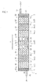
- FIG. 1 shows a sectional structure of the whole portion of a fuel reformer 1.
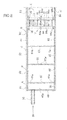
- FIG. 2 shows an enlarged sectional structure on the introduction port 52 side
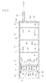
- FIG. 3 shows an enlarged sectional structure on the discharge port 53 side.
- FIG. 2 and FIG. 3 omit illustration of fuel-reforming grains 2, 3 for the convenience of explanation.
- housing compartments B to D provided inside a cylindrical container 4 have a first fuel-reforming grains 2 mainly composed of a rare earth ore housed therein, and a housing compartment "A" has a second fuel-reforming grains 3, mainly composed of quartz and garnet, housed therein.
- the fuel reformer 1 is provided typically as being inserted on a fuel supply path ranging from a fuel tank to an engine of a vehicle, allowing a petroleum-derived liquid fuel (in particular diesel oil, simply referred to as liquid fuel, hereinafter) reserved in the fuel tank of the vehicle to flow through the fuel supply path and through an introduction port 52 into the cylindrical container 4, and allowing it to modify with the aid of the first fuel-reforming grains 2, the second fuel-reforming grains 3 and permanent magnet 71.
- the engine supplied with thus-modified liquid fuel through the discharge port 53 raises effects of improving the combustion efficiency, improving the fuel cost, and reducing the emission gas.
- the first fuel-reforming grain 2 comprises, as shown in the sectional view in FIG. 11, a ceramic grain 22 obtained by molding and sintering a mixture containing rare earth ore powder and a binder (pot earth, etc.), and a rare earth ceramic layer 21 formed on the surface thereof.
- the rare earth ore is a naturally occurred one, containing silicon dioxide (SiO 2 ) and alumina (Al 2 O 3 ) as major components of the ore, as well as 3% or more, for example, of oxides of rare earth elements (e.g., oxides of Y, La and Ce), and trace amounts of radioactive elements such as uranium (U) and thorium (Th). These components are said to emit minus ions and far infrared radiation.
- the rare earth ceramic layer 21 comprises a mixed powder of rare earth ore powder and Ti and Ag powders deposited on the surface of the ceramic grains 22.
- the mixed powder may be composed of rare earth ore powder, typically mixed with approximately 0.5 to 5wt% of Ti powder, and approximately 0.1 to 3wt% of Ag powder.
- the Ti powder and Ag powder may typically be a pure Ti powder and a pure Ag powder (e.g., with a purity of 99% or above).
- FIG. 16 shows process steps of manufacture of the first fuel-reforming grains 2.
- a rare earth ore RE as a major component of the rare earth ceramic layer 21 and the ceramic grain 22 is crushed to obtain a powder RP.
- the powder RP of the rare earth ore RE is mixed with pot earth and so forth, molded to obtain green ceramic grains 22G with a spherical shape, sintered at a temperature around 1,200 to 1,400°C, to thereby obtain the ceramic grains 22 (process step 2).
- a mixed power PW is allowed to deposit on the ceramic grains 22 (process step 3).
- the mixed powder PW comprises the powder RP of the rare earth ore RE, and Ti powder and Ag powder mixed therewith.
- Deposition of the mixed powder can be realized using a spraying device spraying the mixed powder PW together with a highly-compressed gas produced by a compressor (not shown), from a spraying nozzle NZ.
- a spraying device spraying the mixed powder PW together with a highly-compressed gas produced by a compressor (not shown), from a spraying nozzle NZ.
- the collision of the mixed powder PW raises the surface temperature of the ceramic grains 22 to as high as the melting point (1,800°C or around) thereof, and the mixed powder is deposited on the melted surface to thereby form the rare earth ceramic layer 21.
- the deposition is carried out in a nitrogen atmosphere in order to avoid excessive oxidation of the mixed powder PW.
- the second fuel-reforming grains 3 are obtained by molding and sintering a mixture containing quartz powder, garnet powder, tourmaline powder, a binder (pot earth, etc.) and so forth. Quartz is a crystalline silicon dioxide (SiO 2 ), for which rock crystal is available. Garnet is a kind of silicate ores. Tourmaline is also a kind of silicate ore, has a piezoelectric effect and pyroelectric effect, so that it generates electric charge when applied with external pressure or temperature changes. These ores are said to emit far infrared radiation.
- the second fuel-reforming grains 3 are sintered at around 1,200 to 1,400°C.
- the cylindrical container 4 comprises a cylinder component 41 and end wall plates 42, 43 disposed at the end portions on the upstream and downstream sides.
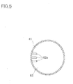
- the end wall plates 42, 43 have an introduction port 52 and a discharge port 53 (FIG. 9), respectively, and the direction from the introduction port 52 to the discharge port 53 is referred to as the direction of flow R of the liquid fuel in the cylindrical container 4.
- the cylindrical container 4 and internal components (61 to 64, 81 to 83, etc.), described later, are composed of a non-magnetic stainless steel, such as SUS301 (austenitic stainless steel). Joint portions Y of the cylinder component 41 and the end wall plates 42, 43 are formed by argon arc welding.
- the inner wall surface of the cylindrical container 4 and the surface of the internal components have, formed thereon, a rare earth ceramic layer which is similar to the rare earth ceramic layer 21 provided to the surficial portion of the first fuel-reforming grains 2, also by which the fuel-reforming effect is obtained.
- the rare earth ceramic layer can be formed using the above-described deposition process (spraying device). More specifically, when the above-described mixed powder is sprayed together with a highly-compressed gas, the surface temperature of the cylindrical container 4 made of a stainless steel rises to as high as its melting point (1,680°C or around) due to collision of the mixed powder, and the mixed powder is allowed to deposit on the melted surface, to thereby form the rare earth ceramic layer. The collision of the mixed powder also results in work hardening of the (austenitic) stainless steel, and this is successful in obtaining the cylindrical container 4 of a high strength.
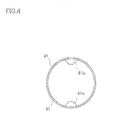
- diaphragms (simply referred to as diaphragm, hereinafter) 61 to 64, having through-holes 61 a to 64a for the liquid fuel formed therein, so as to partition the inner space of the container, as shown in FIGs. 4 to 7B.
- diaphragm perforated diaphragms
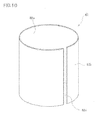
- the spacer 82 has a cylindrical form with a diameter almost equal to the inner diameter of the cylinder component 41 of the cylindrical container 4, and has a slit 82s, facilitating engagement thereof with the cylinder component 41, formed in the direction of axial line thereof.
- the spacer 82 inserted into the cylinder component 41 so as to engage therewith contacts on the outer surface 82b thereof with the inner wall of the cylinder component 41, and so as to respectively face to the rim portions of the diaphragms 61 to 64.
- the spacer 82 also immobilizes the diaphragms so that the edge portions 82c, 82d thereof are abutted with the rim portions of the main surfaces of the diaphragms 61 to 64.
- the inner space of the cylindrical container 4 is partitioned by the diaphragms 61 to 64 and the spacers 81 O 83 into a plurality of housing compartments A to E lying in a row in the direction of flow R of the liquid fuel, and each of the housing compartments A to E has the first fuel-reforming grains 2 (2a, 2b) and second fuel-reforming grains 3 housed therein.
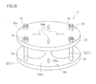
- a magnet unit 7 as is shown in Fig.8, having a permanent magnet 71 held between a pair of diaphragms 64.
- the permanent magnet 71 is composed of an Nd-Fe-B-base sintered magnet, and is covered with a metal jacket 72 (made of SUS301).
- One main surface 64m of the diaphragm 64 has, formed therein, a recess 64b with which the permanent magnet 71 is engaged (FIG. 7A), and two diaphragms 64 hold the permanent magnet 71 in between, while opposing the main surfaces 64m thereof, and making the individual end portions of the permanent magnet 71 engage with the respective recesses 64b.
- the diaphragms 64 have screw holes 64c bored therein (FIGs. 7A, 7B), so that two diaphragms 64 are fixed using bolts 79 and nuts 78.
- the magnet unit 7 has a plurality of permanent magnets 71 which are arranged so as to alternate the polarity of both ends of every adjacent permanent magnets 71. Two magnet units 7 are arranged in the cylindrical container, and a space therebetween serves as a hausing compartment E. Effects expected from setting of the magnet units 7 in the cylindrical container 4 are as described in the above.
- Through-holes 61a to 63a for the liquid fuel, formed in the diaphragms 61 to 63, are configured by notches formed at the peripheral portions of the diaphragms 61 to 63, as shown in FIGs . 4 to 6.
- the diaphragms 61 to 63 are arranged according to orientations shown in FIGs. 4 to 6. Bringing now the diaphragm 62 into focus, through-holes 62a are arranged at positions 90° rotated from the positions corresponded to through-holes 61a, 63a formed in the adjacent diaphragms 61, 63.
- the off-alignment of the through-holes 61a to 63a can elongate the length of flow path of liquid fuel in the cylindrical container 4, so that it is made possible to elongate the duration of time of contact between the liquid fuel and the fuel-reforming grains 2, 3.
- housing compartments A to E are arranged symmetrically about the housing compartment E disposed between two magnet units 7, on the upstream and downstream sides (on the left-hand and right-hand sides in the drawing), and the housing compartment "A" houses the second fuel-reforming grains 3, and the housing compartments B to E house the first fuel-reforming grains 2 (2a, 2b).
- the housing compartment A on the introduction port 52 side is designed to house the second fuel-reforming grains 3, because this configuration makes it possible to allow the second fuel-reforming grains 3 to initially contact with the liquid fuel introduced through the introduction port 52, to thereby avoid adhesion of foul onto the first fuel-reforming grains 2 (2a, 2b) in the housing compartments B to E.
- the housing compartment "A” on the discharge port 53 side is designed to house the second fuel-reforming grains 3, in order to prevent foul adhesion typically on to the engine, a destination of flow of the liquid fuel.
- the first fuel-reforming grains 2 are classified into the first fuel-reforming grains 2b having small diameters (6 to 10 mm or around: first size) and the first fuel-reforming grains 2a having large diameters (10 to 14 mm or around: second size), wherein the first fuel-reforming grains 2b of small diameters are housed in the housing compartment C, and the first fuel-reforming grains 2b of large diameters are housed in the housing compartments B, D and E.
- the first fuel-reforming grains 2b of small diameters preferably have sizes of 70 to 80% of those of the first fuel-reforming grains 2a of large diameters. The reason why the first fuel-reforming grains 2a, 2b are housed by size into the housing compartments B to E is as follows.
- the first fuel-reforming grains 2b having smaller diameters can give a thorough fuel-reforming effect by virtue of their large total surface area which can contact with the liquid fuel, but have only a small gap allowing the liquid fuel to flow therethrough, and this may increase the flow resistance, and may burden heavily on the engine or the like.
- Combined use of the first fuel-reforming grains 2b of small diameters and the first fuel-reforming grains 2a of large diameters is, therefore, successful in achieving a thorough fuel-reforming effect while keeping the flow resistance of the liquid fuel lowered at an appropriate level.
- the fuel reformer has three or more successive housing compartments having the first fuel-reforming grains 2a of large diameters housed therein (housing compartments D-->E-->D).
- housing compartments D-->E-->D housing compartments D-->E-->D
- Fig.1 it is still also preferable, in view of keeping the flow resistance of the liquid fuel at an appropriate level, to house the fuel-reforming grains 2b, 3 of small diameters, and the fuel-reforming grains 2a of large diameters alternately into a plurality of housing compartments A to D disposed in regions ranging from the end walls 42, 43, respectively having the introduction port 52 and discharge port 53, towards the magnet unit 7. It is also allowable to house the ceramic grains 22, having no rare earth ceramic layer 21 formed thereon (see FIG.
- the fuel reformer 1 can be fabricated as follows. First, the cylinder component 41 and the end wall plate 42 are welded by argon arc welding, and according to the order of arrangement shown in FIG. 1, the first fuel-reforming grains 2 (2a, 2b), second fuel-reforming grains 3, diaphragms 61 to 64, spacers 81 to 83 and magnet unit 7 are placed therein from the opposite end portion of the cylinder component 41.
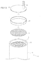
- FIG. 12 shows an exemplary case of forming the housing compartment C on the introduction port 52 side.
- the cylinder component 41 before formation of the housing compartment C, has the first fuel-reforming grains 2a of large diameters and the spacer 82, both composing the housing compartment B, exposed to the topmost therein (not shown).
- Insertion of the diaphragms 61 to 64 into the cylinder component 41 may sometimes result in inclined setting thereof in the cylinder component 41, so that it is allowable to use a diaphragm 65, as shown in FIG. 14, having a nut-formed engagement portion 65n on one main surface thereof.
- a diaphragm 65 as shown in FIG. 14, having a nut-formed engagement portion 65n on one main surface thereof.
- Fig.15 it is made possible to correctly insert the diaphragm 65 into the cylinder component 41, by using an insertion rod 65b having a bolt-formed end capable of engaging with the engagement portion 65n. After insertion of the diaphragm 65, the insertion rod 65b can be detached from the engagement portion 65n, and only the insertion rod 65b is drawn out last.
- a mesh component (a net made of metal, for example) 9, having a mesh size smaller than the second fuel-reforming grains 3, as being disposed between the end wall plate 43 having the discharge port 53, and the second fuel-reforming grains 3 (FIG. 3).
- a spacer 84 is disposed (FIG. 3).
- the spacer 84 has the same geometry with other spacers 81 to 83, except that it has a shorter length in the direction of axial line. This configuration can be obtained by inserting, in the final stage of the insertion into the cylinder component 41 as shown in FIG.
- the present inventors then attached the fuel reformer according to the embodiment of the present invention to four diesel vehicles (three 10-t vehicles and one 7-t vehicle), of which grace periods will soon expire or have already expired, and submitted the vehicles to Japan Vehicle Inspection Association (inspection agency licensed by Ministry of Land Infrastructure and Transport, Japan) for the diesel vehicle emission gas test (6-mode).
- the test was conducted by allowing the vehicles to drive on rollers directly coupled with a chassis dynamometer, under the same load with road driving, and by measuring amount of emission gas from the vehicles.
- Targets of the measurement include CO, HC and NOx.
- Mean emission concentration filled in test sheets (6-mode) for diesel vehicle emission gas test are shown together with the regulatory values (the National Motor Vehicle NOx and PM Emissions Act values) in Tables 1 to 4.
Landscapes
- Chemical & Material Sciences (AREA)
- Organic Chemistry (AREA)
- Chemical Kinetics & Catalysis (AREA)
- Engineering & Computer Science (AREA)
- Combustion & Propulsion (AREA)
- General Health & Medical Sciences (AREA)
- Physics & Mathematics (AREA)
- Fluid Mechanics (AREA)
- Health & Medical Sciences (AREA)
- Ceramic Engineering (AREA)
- Materials Engineering (AREA)
- Structural Engineering (AREA)
- Manufacturing & Machinery (AREA)
- Oil, Petroleum & Natural Gas (AREA)
- Toxicology (AREA)
- Mechanical Engineering (AREA)
- General Engineering & Computer Science (AREA)
- Inorganic Chemistry (AREA)
- General Chemical & Material Sciences (AREA)
- Liquid Carbonaceous Fuels (AREA)
- Catalysts (AREA)
Applications Claiming Priority (1)
| Application Number | Priority Date | Filing Date | Title |
|---|---|---|---|
| JP2005081637A JP2006265293A (ja) | 2005-03-22 | 2005-03-22 | 燃料改質装置 |
Publications (1)
| Publication Number | Publication Date |
|---|---|
| EP1705362A2 true EP1705362A2 (de) | 2006-09-27 |
Family
ID=35311758
Family Applications (1)
| Application Number | Title | Priority Date | Filing Date |
|---|---|---|---|
| EP05107919A Withdrawn EP1705362A2 (de) | 2005-03-22 | 2005-08-30 | Brennstoffreformer |
Country Status (5)
| Country | Link |
|---|---|
| US (1) | US20060213124A1 (de) |
| EP (1) | EP1705362A2 (de) |
| JP (1) | JP2006265293A (de) |
| KR (1) | KR20060102260A (de) |
| CN (1) | CN1837134A (de) |
Cited By (1)
| Publication number | Priority date | Publication date | Assignee | Title |
|---|---|---|---|---|
| WO2009149969A1 (de) * | 2008-05-28 | 2009-12-17 | Robert Bosch Gmbh | Vorrichtung zur stabilisierung oxidierbarer flüssigkeiten sowie verwendung der vorrichtung |
Families Citing this family (10)
| Publication number | Priority date | Publication date | Assignee | Title |
|---|---|---|---|---|
| WO2008093388A1 (ja) * | 2007-01-29 | 2008-08-07 | Kenichi Hashimoto | 液体燃料の高燃焼効率化装置 |
| KR101296645B1 (ko) | 2007-03-12 | 2013-08-14 | 엘지디스플레이 주식회사 | 쉬프트 레지스터 |
| JP2009209303A (ja) * | 2008-03-06 | 2009-09-17 | Seraphim:Kk | 液体燃料改質装置 |
| KR101077849B1 (ko) * | 2008-06-18 | 2011-10-28 | 정인범 | 친환경 연료 활성화 장치 |
| JP5227706B2 (ja) * | 2008-09-08 | 2013-07-03 | 本田技研工業株式会社 | 改質装置 |
| US9180424B2 (en) * | 2010-09-11 | 2015-11-10 | Albert Chin-Tang Wey | Infrared assisted hydrogen generation |
| CN103590932A (zh) * | 2013-10-16 | 2014-02-19 | 南宁明航节能科技有限公司 | 一种汽车节油器 |
| CN105756816A (zh) * | 2016-04-20 | 2016-07-13 | 刘陈辉 | 燃油裂变器 |
| US11555430B1 (en) | 2019-03-15 | 2023-01-17 | Emissions Science Corporation | Device and method for reducing emissions from an internal combustion engine |
| JP7466190B2 (ja) * | 2020-08-04 | 2024-04-12 | 株式会社環健スーパーテクノ | 改質触媒、その製造方法および改質装置ならびに排ガス浄化装置 |
Family Cites Families (3)
| Publication number | Priority date | Publication date | Assignee | Title |
|---|---|---|---|---|
| JP2548754B2 (ja) * | 1987-12-02 | 1996-10-30 | 三菱重工業株式会社 | 窒素酸化物除去用触媒 |
| US4843815A (en) * | 1988-08-19 | 1989-07-04 | Smojver Radmil R | Catalytic conversion device |
| US5451388A (en) * | 1994-01-21 | 1995-09-19 | Engelhard Corporation | Catalytic method and device for controlling VOC. CO and halogenated organic emissions |
-
2005
- 2005-03-22 JP JP2005081637A patent/JP2006265293A/ja active Pending
- 2005-08-29 US US11/212,746 patent/US20060213124A1/en not_active Abandoned
- 2005-08-30 KR KR1020050080200A patent/KR20060102260A/ko not_active Withdrawn
- 2005-08-30 EP EP05107919A patent/EP1705362A2/de not_active Withdrawn
- 2005-08-31 CN CNA2005100936224A patent/CN1837134A/zh active Pending
Cited By (1)
| Publication number | Priority date | Publication date | Assignee | Title |
|---|---|---|---|---|
| WO2009149969A1 (de) * | 2008-05-28 | 2009-12-17 | Robert Bosch Gmbh | Vorrichtung zur stabilisierung oxidierbarer flüssigkeiten sowie verwendung der vorrichtung |
Also Published As
| Publication number | Publication date |
|---|---|
| US20060213124A1 (en) | 2006-09-28 |
| KR20060102260A (ko) | 2006-09-27 |
| JP2006265293A (ja) | 2006-10-05 |
| CN1837134A (zh) | 2006-09-27 |
Similar Documents
| Publication | Publication Date | Title |
|---|---|---|
| EP1705362A2 (de) | Brennstoffreformer | |
| EP3144048A1 (de) | Abgasreinigungsvorrichtung | |
| WO2004109069A1 (ja) | 排気浄化装置 | |
| HUE026312T2 (en) | Method for optimizing combustion engines | |
| JPWO1998042807A1 (ja) | 低公害燃料の製造方法及びその製造装置 | |
| CN104583551A (zh) | 氨气存储单元及相关的结构和系统 | |
| US6178953B1 (en) | Magnetic fluid treatment apparatus for internal combustion engine and method thereof | |
| JP3357281B2 (ja) | 内燃機関の排気ガスから窒素酸化物を除去する装置 | |
| JP2018003605A (ja) | プラズマリアクタ | |
| US7406956B2 (en) | Device for enhancing combustion efficiency | |
| JPH1112022A (ja) | セラミック塊状体及び燃料改質装置 | |
| JP2006307864A (ja) | 燃料改質装置 | |
| US9221126B2 (en) | Method for producing a cellular wheel | |
| KR101114512B1 (ko) | 매연 저감을 위한 연료 개질 장치 | |
| KR101774800B1 (ko) | 요소수 주입구 일체형 디젤연료 주입구 구조 | |
| JPH1046162A (ja) | ペレット型液体燃料改質材 | |
| JP2006026537A (ja) | 排ガス浄化装置、および排ガス浄化装置の製造方法 | |
| HK1097248A (en) | Fuel reformer | |
| JP2008309072A (ja) | 内燃機関の排気浄化装置及び、排気浄化素子の保持部材 | |
| JPH1077916A (ja) | 内燃機関における燃料の燃焼効率促進装置 | |
| JPH04301114A (ja) | 内燃機関の排気ガス浄化用フィルタ | |
| CN1630779A (zh) | 热机用液体燃料活性化装置 | |
| JPH0949462A (ja) | 液体燃料活性化装置 | |
| KR20090108899A (ko) | 자동차 배출가스 여과처리장치 | |
| JP2004257295A (ja) | 燃料改質器、流入空気改質器及び改良内燃機関 |
Legal Events
| Date | Code | Title | Description |
|---|---|---|---|
| PUAI | Public reference made under article 153(3) epc to a published international application that has entered the european phase |
Free format text: ORIGINAL CODE: 0009012 |
|
| AK | Designated contracting states |
Kind code of ref document: A2 Designated state(s): AT BE BG CH CY CZ DE DK EE ES FI FR GB GR HU IE IS IT LI LT LU LV MC NL PL PT RO SE SI SK TR |
|
| AX | Request for extension of the european patent |
Extension state: AL BA HR MK YU |
|
| STAA | Information on the status of an ep patent application or granted ep patent |
Free format text: STATUS: THE APPLICATION IS DEEMED TO BE WITHDRAWN |
|
| 18D | Application deemed to be withdrawn |
Effective date: 20090303 |