EP1705365A2 - Injecteur de carburant avec contrôle direct de l'aiguille et amplificateur variable de course - Google Patents
Injecteur de carburant avec contrôle direct de l'aiguille et amplificateur variable de course Download PDFInfo
- Publication number
- EP1705365A2 EP1705365A2 EP06100702A EP06100702A EP1705365A2 EP 1705365 A2 EP1705365 A2 EP 1705365A2 EP 06100702 A EP06100702 A EP 06100702A EP 06100702 A EP06100702 A EP 06100702A EP 1705365 A2 EP1705365 A2 EP 1705365A2
- Authority
- EP
- European Patent Office
- Prior art keywords
- fuel injector
- piston
- valve member
- spring element
- injection valve
- Prior art date
- Legal status (The legal status is an assumption and is not a legal conclusion. Google has not performed a legal analysis and makes no representation as to the accuracy of the status listed.)
- Granted
Links
- 238000002347 injection Methods 0.000 title claims abstract description 51
- 239000007924 injection Substances 0.000 title claims abstract description 51
- 239000000446 fuel Substances 0.000 title claims description 53
- 230000005540 biological transmission Effects 0.000 claims description 5
- 238000002485 combustion reaction Methods 0.000 claims description 4
- 230000003313 weakening effect Effects 0.000 claims 1
- 230000008878 coupling Effects 0.000 description 10
- 238000010168 coupling process Methods 0.000 description 10
- 238000005859 coupling reaction Methods 0.000 description 10
- 238000000418 atomic force spectrum Methods 0.000 description 5
- 238000004804 winding Methods 0.000 description 3
- 230000009471 action Effects 0.000 description 2
- 239000000243 solution Substances 0.000 description 2
- 230000004308 accommodation Effects 0.000 description 1
- 230000008859 change Effects 0.000 description 1
- 230000007423 decrease Effects 0.000 description 1
- 230000001419 dependent effect Effects 0.000 description 1
- 238000005516 engineering process Methods 0.000 description 1
- 239000012530 fluid Substances 0.000 description 1
- 238000004519 manufacturing process Methods 0.000 description 1
- 238000000034 method Methods 0.000 description 1
- 230000036316 preload Effects 0.000 description 1
- 230000008569 process Effects 0.000 description 1
- 230000000284 resting effect Effects 0.000 description 1
- 230000007704 transition Effects 0.000 description 1
Images



Classifications
-
- F—MECHANICAL ENGINEERING; LIGHTING; HEATING; WEAPONS; BLASTING
- F02—COMBUSTION ENGINES; HOT-GAS OR COMBUSTION-PRODUCT ENGINE PLANTS
- F02M—SUPPLYING COMBUSTION ENGINES IN GENERAL WITH COMBUSTIBLE MIXTURES OR CONSTITUENTS THEREOF
- F02M45/00—Fuel-injection apparatus characterised by having a cyclic delivery of specific time/pressure or time/quantity relationship
- F02M45/12—Fuel-injection apparatus characterised by having a cyclic delivery of specific time/pressure or time/quantity relationship providing a continuous cyclic delivery with variable pressure
-
- F—MECHANICAL ENGINEERING; LIGHTING; HEATING; WEAPONS; BLASTING
- F02—COMBUSTION ENGINES; HOT-GAS OR COMBUSTION-PRODUCT ENGINE PLANTS
- F02M—SUPPLYING COMBUSTION ENGINES IN GENERAL WITH COMBUSTIBLE MIXTURES OR CONSTITUENTS THEREOF
- F02M45/00—Fuel-injection apparatus characterised by having a cyclic delivery of specific time/pressure or time/quantity relationship
- F02M45/02—Fuel-injection apparatus characterised by having a cyclic delivery of specific time/pressure or time/quantity relationship with each cyclic delivery being separated into two or more parts
- F02M45/04—Fuel-injection apparatus characterised by having a cyclic delivery of specific time/pressure or time/quantity relationship with each cyclic delivery being separated into two or more parts with a small initial part, e.g. initial part for partial load and initial and main part for full load
- F02M45/08—Injectors peculiar thereto
- F02M45/083—Having two or more closing springs acting on injection-valve
-
- F—MECHANICAL ENGINEERING; LIGHTING; HEATING; WEAPONS; BLASTING
- F02—COMBUSTION ENGINES; HOT-GAS OR COMBUSTION-PRODUCT ENGINE PLANTS
- F02M—SUPPLYING COMBUSTION ENGINES IN GENERAL WITH COMBUSTIBLE MIXTURES OR CONSTITUENTS THEREOF
- F02M51/00—Fuel-injection apparatus characterised by being operated electrically
- F02M51/06—Injectors peculiar thereto with means directly operating the valve needle
- F02M51/0603—Injectors peculiar thereto with means directly operating the valve needle using piezoelectric or magnetostrictive operating means
-
- F—MECHANICAL ENGINEERING; LIGHTING; HEATING; WEAPONS; BLASTING
- F02—COMBUSTION ENGINES; HOT-GAS OR COMBUSTION-PRODUCT ENGINE PLANTS
- F02M—SUPPLYING COMBUSTION ENGINES IN GENERAL WITH COMBUSTIBLE MIXTURES OR CONSTITUENTS THEREOF
- F02M2200/00—Details of fuel-injection apparatus, not otherwise provided for
- F02M2200/26—Fuel-injection apparatus with elastically deformable elements other than coil springs
-
- F—MECHANICAL ENGINEERING; LIGHTING; HEATING; WEAPONS; BLASTING
- F02—COMBUSTION ENGINES; HOT-GAS OR COMBUSTION-PRODUCT ENGINE PLANTS
- F02M—SUPPLYING COMBUSTION ENGINES IN GENERAL WITH COMBUSTIBLE MIXTURES OR CONSTITUENTS THEREOF
- F02M2200/00—Details of fuel-injection apparatus, not otherwise provided for
- F02M2200/70—Linkage between actuator and actuated element, e.g. between piezoelectric actuator and needle valve or pump plunger
- F02M2200/703—Linkage between actuator and actuated element, e.g. between piezoelectric actuator and needle valve or pump plunger hydraulic
Definitions
- the invention relates to a fuel injector with direct control of the injection valve member and variable ratio according to the preamble of claim 1.
- EP 1 174 615 A2 refers to a fuel injector.
- the fuel injector includes a valve member which cooperates with a valve seat and thereby controls the fuel delivery of the injector.
- an actuator assembly and a hydraulic translator which serve to transmit the movement of the actuator assembly to the valve member.
- the pressure translation device comprises a piston and a control chamber, wherein the actuator assembly cooperates with the piston element and exerts a retraction force on the piston element.
- the pressure booster assembly is configured such that it pulls the valve member from the seat by the piston member upon application of an initial retraction force on the piston member.
- valve member The movement of the valve member is decoupled from the piston member such that initial movement of the valve member out of its seat and further movement of the valve member from the actuator assembly to the valve member is transmitted through the fluid within the control chamber, the pressure translator providing variable translation of movement of the actuator assembly ensures the valve member.
- a fuel injector includes a piezo actuator that actuates an injection valve member. This is acted upon via a spring element in the closing direction.
- the fuel injector further includes a hydraulic coupling space hydraulically connecting a booster piston and the injection valve member.
- a sleeve-shaped body On the injection valve member, a sleeve-shaped body is supported, which cooperates with an intermediate stroke stop for the injection valve member forming edge.
- the out EP 1 174 615 A2 known fuel injector has an unfavorable in terms of manufacturing technology structure due to its nested pistons.
- the solution according to DE 10 2004 028 522.5 adheres to the disadvantage that in the realized there two-stage hydraulic translation of the stroke of a piezoelectric actuator when switching the translation creates a force jump. This means that the actuator used must generate the force jump by an additional stroke, but during this additional stroke, preferably designed as a nozzle needle injection valve member does not move. This in turn means that in this phase, no stroke control of the preferably designed as a nozzle needle injection valve member is possible. However, this represents a highly undesirable condition.
- a fuel injector is proposed with a two-stage, hydraulic ratio of Aktorhubes that already builds in the switching phase or during the action of the first gear ratio, the force for the necessary force jump, without the injector is stationary and in particular during the switching of the first level of translation in the second stage of the translation does not come to a standstill.
- a stroke of the injection valve member which can preferably be embodied as a nozzle needle, which can be controlled in the first transmission phase of the two-stage hydraulic transmission over a larger voltage range of the actuator.
- a pre-injection quantity to be injected into the combustion chamber of an internal combustion engine as part of a pre-injection phase can be set much more accurately.
- the spring used can be displayed in various design variants. Common to all variants is the fact that the spring is as compact and small builds to have the smallest possible hydraulic volume in the control room.
- the spring used for the bias can be formed as a plate spring, as a tube spring or as well as coil spring. Except as a separate single component, the spring can also be designed integrated on the piston element. This variant is very advantageous because it has little tolerance.
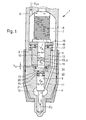
- Figure 1 is a longitudinal section through an inventively proposed fuel injector with direct control of the injection valve member and a variable ratio of the stroke of a piezoelectric actuator refer.
- a fuel injector 1 comprises an injector body 2, which is also referred to as a holding body.
- the injector body 2 of the fuel injector 1 is connected via a clamping nut 4 with a nozzle body 3 to a screw 5.
- the injector body 2 comprises a high-pressure port 6, via which a cavity formed in the injector body 2 is pressurized with system pressure p CR , for example with the fuel pressure level prevailing in a high-pressure accumulator (common rail).
- system pressure p CR system pressure
- a nozzle chamber inlet 11 extends to a nozzle body 3 formed in the nozzle chamber 10, which surrounds an injector member 9 can be formed, for example, as a nozzle needle.
- a pressure stage is formed on the needle-shaped injection valve member 9.
- the needle-shaped injection valve member 9 is acted upon in the opening direction.
- a piezoelectric actuator 8 is received in the cavity 7 of the injector 2.
- the piezoelectric actuator 8 is shown only schematically in the illustration according to FIG. 1 and comprises a multitude of piezocrystals arranged stacked on top of one another, which undergo a change in length when the piezoelectric actuator 8 is energized. As a result, the piezoactuator 8 expands within the cavity 7 of the injector body 2 in the vertical direction and thereby provides the forces required for actuating the injection valve member 9.
- FIG. 1 shows that a pre-lifting sleeve 13 encloses both a first piston 12 and a second piston 14.
- the two mutually facing end faces of the first piston 12 and the second piston 14 and the two pistons 12 and 14 surrounding Vorhubhülse 13 define a hydraulic coupling space 23.
- the outer diameter of the Vorhubhülse 13 is denoted by d V.
- the disc-shaped stop 18 acts on both an inner spring element 16 and an outer spring element 17, which can be formed, for example, both as spiral springs.
- the inner spring element 16 is supported on an end face of the Vorhubhülse 13, while the outer spring element 17 is supported on a surface of the injector body 2, which in turn surrounds the Vorhubhülse 13.
- Both the injector body 2 and the Vorhubhülse 13 lie with their the piezoelectric actuator 8 facing away from end faces along a parting line on an upper end face of the nozzle body 3.
- the diameter of the first piston 12 is indicated by d A.
- a cavity is formed below the Vorhubhülse 13 lying in the nozzle body 3 of the fuel injector 1 as shown in Figure 1, a cavity is formed.
- the second piston 14 is received, protrudes the tapered end in the Vorhubhülse 13 and opposite to the end face of the first piston 12 within the coupling space 23.
- a biasing spring 21 is received, which is supported on the one hand on a collar 22 of the second piston 14 and on the other hand on a lower end face of the Vorhubhülse 13.
- the cavity and a piston end face 19 of the second piston 14 acted upon control chamber 20 are hydraulically connected.
- the piston end face 19 rests in a plane surface of the nozzle body 3 above the injection valve member 9 accommodated therein.
- control chamber 20 below the second piston 14, on which the biasing spring 21 is accommodated, is the control chamber 20, in which a control chamber spring element 15 is received.
- the control chamber spring element 15 rests on the one hand on the piston end face 19 of the second piston 14 and on the other hand is supported on an end face of the needle-shaped injection valve member 9 from. Diameter of the needle-shaped injection valve member 9 above the nozzle chamber 10 is denoted by d N.
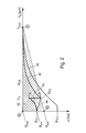
- the illustration according to FIG. 2 shows characteristic curves with respect to the switching energy, the opening pressures and the power stroke characteristic curves of fuel injectors with or without variable translator arrangement.
- the pressure in the coupling space 23 is plotted over the stroke h E of the preferably needle-shaped injection valve member 9. From the opening force curve 40 without steps translation operable for a fuel injector the piezo actuator, it appears that the opening pressure p ⁇ , 3 substantially below the opening pressure p ⁇ , 1 of a fuel injector is operating with a piezoelectric actuator 8 with steps translation.
- a piezoactuator 8 operating without stepped transmission requires a switching energy indicated by the hatched area, given by the triangle abc as shown in FIG. 2.
- the second opening pressure p ⁇ 2 of the preferably needle-shaped injection valve member 9 of a fuel injector 1 with piezoelectric actuator 8 and step ratio is substantially lower. Therefore, a lower actuation force for the injection valve member 9 is required, so that such a piezoelectric actuator 8 has a smaller volume, ie smaller builds and therefore takes up less space.
- the transition to the second translation stage is then no longer in the context of a force jump 43 - as shown in Figure 2 - but continuously.
- the voltage of the actuator 8 can in the presence of a motor crack 43, as shown in Figure 2, crit between U and U min for controlling the injection valve member 9 are controlled, since usually the power jump present 43rd If, on the other hand, a biasing spring 21 is used as proposed according to the invention, the force is continuously built up continuously from 0 until reaching the stroke h V. As can be seen from FIG.
- the injection valve member 9 can thus be continuously controlled between the voltages U crit and U min , whereby a pre-injection can be realized over a larger voltage range, which increases the precision of the pre-injection quantity due to the fine gradation possibilities of the actuator voltage application during the first transmission phase. significantly improved.
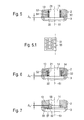
- the biasing spring 21 is formed in the form of a plate spring and extends in the axial direction of the second piston 14 seen.
- ⁇ x a lift gap is designated, which corresponds to the Vorhubweg h V.
- S denotes the thickness of the biasing spring 21 designed as a plate spring.
- the second piston 14 has a collar 22, on the support 53 of which the plate-spring-shaped biasing spring 21 rests.
- the biasing spring 21 is on the other hand on an end face 52 of the Vorhubhülse 13.
- the Vorhubhülse 13 in turn is enclosed by the injector 2 of the fuel injector 1.
- the biasing spring 21 is arranged in the lifting gap .DELTA.x.
- FIG. 3.1 shows that radial grooves 59 for pressure equalization are formed in front face 52 of the pre-stroke sleeve.
- FIG. 4 The illustration according to Figure 4 is shown in a further embodiment of a plate-shaped biasing spring. From the embodiment it is apparent that the plate spring-shaped biasing spring 21 between the collar 22, i. whose support 53 and the lower end face 52 of the Vorhubhülse 13 is received. The lifting gap ⁇ x.
- the second piston 14 and the collar 22 are two separate, mutually separate components.
- the plate spring formed as a biasing spring 21 the biasing force is built up. The taking place due to positive engagement entrainment of the piston 14 takes place after passing through the stroke .DELTA.x. Therefore, the functions of preload and stroke are completely separated.
- Figure 5 shows another embodiment of the biasing spring, designed as a tube spring.
- the biasing spring 21 may be formed as a tube spring, which can be inserted into a receiving space 54 of the Vorhubhülse 13. According to the embodiment variant shown in Figure 5 the biasing spring 21 is supported on an upper side 52 of the receiving space 54 on the one hand and on the support 53 of the collar 22 of the second piston 14 on the other hand. With ⁇ x the lifting gap is designated, which is identical to the Vorhubweg h V.
- Figure 5.1 is a developed view of the lateral surface 55 of a bias spring formed as a tube spring 21.
- the Bourdon tube has a regularly or irregularly arranged pattern of slots and circular openings which may be offset with respect to each other with respect to the axis of symmetry 51 of the biasing spring 21. Due to the design of the slit width or the diameter of the circular end portions formed, the rigidity of a bias spring formed as a tube spring 21 can be adjusted and adapted to the respective purposes in an optimal manner.
- FIG. 6 shows a bias spring formed as a spiral spring.
- the pre-stroke sleeve 13 has a receiving space 54 in which the pretensioning spring 21 designed as a spiral spring is accommodated.
- the biasing spring 21 according to the embodiment shown in Figure 6 is supported on an upper side 52 of the receiving space 54 on the one hand and on the support 53 of the collar 22 of the second piston 14 on the other hand.
- a designed as a spiral or coil spring biasing spring 21 is a particularly cost-effective component.
- FIG. 7 shows a further embodiment of a biasing spring, which is formed on a piston element.
- an integrated spring element 56 is formed on the second piston 14 formed symmetrically with respect to the axis of symmetry 51. This may have at least one contact surface 58 which abuts against the underside of the Vorhubhülse 13. To influence the spring characteristic of the integrated spring element 56, this comprises a ring groove 57 which extends in a circular manner in the integrated spring element 56.
- the integrally formed on the second piston 14 spring element 56 is characterized mainly by the fact that this can hardly be made tolerant. With ⁇ x the lifting gap is designated, which is identical to the stroke h V of the Vorhubhülse.
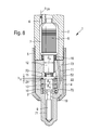
- FIG. 8 shows a fuel injector with an injection valve member with a variable translator arrangement that can be directly actuated via a piezoactuator.
- the fuel injector 1 shown there has, analogously to the fuel injector shown in FIG. 1, a piezoactuator 8 which is arranged within a cavity 7.
- the cavity 7 is acted upon via the high pressure port 6 with system pressure p CR from a high pressure source, not shown, with fuel.
- the injector body 2 is connected to the nozzle body 3 via a clamping sleeve 4.
- a piston guide 73 Located between the injector 2 and the nozzle body 3, also enclosed by the clamping sleeve 4, a piston guide 73.
- the piston guide 73 is as well as the nozzle body 3 traversed by a nozzle chamber inlet 11, which opens into the nozzle chamber 10.
- the piezoelectric actuator 8 acts on a first piston 12, which has an outer diameter d A.
- the first piston 12 protrudes into the coupling space 23, in which also the collar 22, in this embodiment, is connected to the injection valve member 9.
- the pre-lifting sleeve 13 strikes against the underside of the collar 22 and is acted upon by a spring element 70, which in turn is supported in the nozzle body 3.
- an annular gap 71 extends in the direction of the seat of the injection valve member 9. Via the annular gap 71, fuel under the system pressure p CR flows into the injection openings, not shown in FIG. 8, at the end of the nozzle body 3.
- the biasing spring 21 between the underside of the piston guide 73 and the coupling space 23 facing end face of the Vorhubhülse 13 is arranged.
- the biasing spring 21 is supported on the one hand next to the collar 22 lying on the end face 52 of the Vorhubhülse 13 and on the other hand on a contact surface 74 on the underside of the piston guide 73 from.
- the Vorhubhülse 13 encloses the injection valve member 9 and is located on the underside of the collar 22 at.
- the biasing spring 21 is effective along the stroke h V , wherein the stroke h V corresponds to the lifting gap .DELTA.x.
- Figure 9.1 shows a developed section through the piston guide 73, at the contact surface 74 radial grooves 59 are formed for pressure equalization.
- FIGS. 10 and 10.1 show further embodiment variants of biasing springs which can be used on the fuel injector according to the embodiment in FIG.
- the biasing spring 21 can be manufactured as a tube spring with a square winding cross section 80 as shown in Figure 10 or as a tube spring according to Figure 5.1 or with a round spring wire cross section as shown in Figure 10.1. In both cases, the thus configured biasing spring 21 is partially embedded in the piston guide 73 and is applied to this on the contact surface 74 at. The biasing spring 21 is supported on the other hand on the end face 52 of the Vorhubhülse 13. With ⁇ x the lifting gap is designated, during which bridging a biasing force build-up takes place.
- the inventively proposed very stiff designed biasing spring 21 can be as described above both on fuel injectors according to the embodiment in Figure 1 and fuel injectors according to the embodiment in Figure 8 use.
- the biasing spring 21, which can be formed both as a plate spring, a tube spring, a coil spring or as a spring element integrated on the piston 14, avoids the force jump 73 shown in FIG. 2 and replaces it with a continuous force build-up according to the characteristic curve 44 according to FIG.
- the force for the previously required force jump 43 can be gradually built up, without the injection valve member 9 resting, but constantly moving.
Landscapes
- Engineering & Computer Science (AREA)
- Chemical & Material Sciences (AREA)
- Combustion & Propulsion (AREA)
- Mechanical Engineering (AREA)
- General Engineering & Computer Science (AREA)
- Fuel-Injection Apparatus (AREA)
Applications Claiming Priority (1)
| Application Number | Priority Date | Filing Date | Title |
|---|---|---|---|
| DE102005012929A DE102005012929A1 (de) | 2005-03-21 | 2005-03-21 | Kraftstoffinjektor mit direkter Steuerung des Einspritzventilglieds und variabler Übersetzung |
Publications (3)
| Publication Number | Publication Date |
|---|---|
| EP1705365A2 true EP1705365A2 (fr) | 2006-09-27 |
| EP1705365A3 EP1705365A3 (fr) | 2009-02-18 |
| EP1705365B1 EP1705365B1 (fr) | 2010-11-03 |
Family
ID=36588928
Family Applications (1)
| Application Number | Title | Priority Date | Filing Date |
|---|---|---|---|
| EP06100702A Expired - Lifetime EP1705365B1 (fr) | 2005-03-21 | 2006-01-23 | Injecteur de carburant avec contrôle direct de l'aiguille et amplificateur variable de course |
Country Status (4)
| Country | Link |
|---|---|
| US (1) | US20060208107A1 (fr) |
| EP (1) | EP1705365B1 (fr) |
| AT (1) | ATE487052T1 (fr) |
| DE (2) | DE102005012929A1 (fr) |
Cited By (2)
| Publication number | Priority date | Publication date | Assignee | Title |
|---|---|---|---|---|
| AT511075A4 (de) * | 2011-05-26 | 2012-09-15 | Avl List Gmbh | Zweistoffbrennkraftmaschine |
| US12065995B2 (en) * | 2021-05-12 | 2024-08-20 | Hitachi Astemo, Ltd | Fuel injection device |
Families Citing this family (9)
| Publication number | Priority date | Publication date | Assignee | Title |
|---|---|---|---|---|
| DE10326259A1 (de) * | 2003-06-11 | 2005-01-05 | Robert Bosch Gmbh | Injektor für Kraftstoff-Einspritzsysteme von Brennkraftmaschinen, insbesondere von direkteinspritzenden Dieselmotoren |
| DE102004027824A1 (de) * | 2004-06-08 | 2006-01-05 | Robert Bosch Gmbh | Kraftstoffinjektor mit variabler Aktorübersetzung |
| DE102006008648A1 (de) * | 2006-02-24 | 2007-08-30 | Robert Bosch Gmbh | Kraftstoffeinspritzvorrichtung für eine Brennkraftmaschine |
| JP4459183B2 (ja) * | 2006-03-16 | 2010-04-28 | 株式会社デンソー | インジェクタ |
| DE112012004564T5 (de) | 2011-11-01 | 2014-08-21 | Cummins Inc. | Kraftstoff-Einspritzungsvorrichtung mit Einspritzregelventilpatrone |
| DE102013219225A1 (de) * | 2013-09-25 | 2015-03-26 | Continental Automotive Gmbh | Piezo-Injektor zur Kraftstoff-Direkteinspritzung |
| EP3102817A4 (fr) * | 2014-02-07 | 2017-11-01 | EcoMotors, Inc. | Ressort préchargé destiné à être utilisé avec un injecteur de carburant piézoélectrique |
| DE102016109073B4 (de) * | 2015-06-05 | 2022-02-17 | Denso Corporation | Kraftstoffeinspritzventil und Kraftstoffeinspritzventilcontroller |
| CN107664081A (zh) * | 2016-07-29 | 2018-02-06 | 博世有限公司 | 用于燃料喷射器的碟形弹簧 |
Citations (2)
| Publication number | Priority date | Publication date | Assignee | Title |
|---|---|---|---|---|
| EP1174615A2 (fr) | 2000-07-18 | 2002-01-23 | Delphi Technologies, Inc. | Injecteur de combustible |
| DE102004028522A1 (de) | 2004-06-11 | 2005-12-29 | Robert Bosch Gmbh | Kraftstoffinjektor mit variabler Aktorhubübersetzung |
Family Cites Families (12)
| Publication number | Priority date | Publication date | Assignee | Title |
|---|---|---|---|---|
| US4022166A (en) * | 1975-04-03 | 1977-05-10 | Teledyne Industries, Inc. | Piezoelectric fuel injector valve |
| DE2931874C2 (de) * | 1979-08-06 | 1983-08-04 | Audi Nsu Auto Union Ag, 7107 Neckarsulm | Elektrisch betätigbares Ventil |
| US5482213A (en) * | 1993-05-31 | 1996-01-09 | Aisin Seiki Kabushiki Kaisha | Fuel injection valve operated by expansion and contraction of piezoelectric element |
| GB9615663D0 (en) * | 1996-07-25 | 1996-09-04 | Lucas Ind Plc | Fuel pumping apparatus |
| US5947380A (en) * | 1997-11-03 | 1999-09-07 | Caterpillar Inc. | Fuel injector utilizing flat-seat poppet valves |
| DE19758066A1 (de) * | 1997-12-29 | 1999-07-01 | Steyr Daimler Puch Ag | Pumpedüse vom Typ mit offener Einspritzdüse |
| DE19843535A1 (de) * | 1998-09-23 | 2000-03-30 | Bosch Gmbh Robert | Brennstoffeinspritzventil |
| EP1041272B1 (fr) * | 1999-04-01 | 2004-10-27 | Delphi Technologies, Inc. | Injecteur de combustible |
| DE10032517A1 (de) * | 2000-07-05 | 2002-01-24 | Bosch Gmbh Robert | Injektor mit Steuerteilführung |
| US6766965B2 (en) * | 2001-08-31 | 2004-07-27 | Siemens Automotive Corporation | Twin tube hydraulic compensator for a fuel injector |
| DE10326259A1 (de) * | 2003-06-11 | 2005-01-05 | Robert Bosch Gmbh | Injektor für Kraftstoff-Einspritzsysteme von Brennkraftmaschinen, insbesondere von direkteinspritzenden Dieselmotoren |
| DE102005004738A1 (de) * | 2005-02-02 | 2006-08-10 | Robert Bosch Gmbh | Kraftstoffinjektor mit direkter Nadelsteuerung für eine Brennkraftmaschine |
-
2005
- 2005-03-21 DE DE102005012929A patent/DE102005012929A1/de not_active Withdrawn
-
2006
- 2006-01-23 DE DE502006008205T patent/DE502006008205D1/de not_active Expired - Lifetime
- 2006-01-23 AT AT06100702T patent/ATE487052T1/de not_active IP Right Cessation
- 2006-01-23 EP EP06100702A patent/EP1705365B1/fr not_active Expired - Lifetime
- 2006-03-17 US US11/377,558 patent/US20060208107A1/en not_active Abandoned
Patent Citations (2)
| Publication number | Priority date | Publication date | Assignee | Title |
|---|---|---|---|---|
| EP1174615A2 (fr) | 2000-07-18 | 2002-01-23 | Delphi Technologies, Inc. | Injecteur de combustible |
| DE102004028522A1 (de) | 2004-06-11 | 2005-12-29 | Robert Bosch Gmbh | Kraftstoffinjektor mit variabler Aktorhubübersetzung |
Cited By (3)
| Publication number | Priority date | Publication date | Assignee | Title |
|---|---|---|---|---|
| AT511075A4 (de) * | 2011-05-26 | 2012-09-15 | Avl List Gmbh | Zweistoffbrennkraftmaschine |
| AT511075B1 (de) * | 2011-05-26 | 2012-09-15 | Avl List Gmbh | Zweistoffbrennkraftmaschine |
| US12065995B2 (en) * | 2021-05-12 | 2024-08-20 | Hitachi Astemo, Ltd | Fuel injection device |
Also Published As
| Publication number | Publication date |
|---|---|
| EP1705365A3 (fr) | 2009-02-18 |
| EP1705365B1 (fr) | 2010-11-03 |
| US20060208107A1 (en) | 2006-09-21 |
| DE502006008205D1 (de) | 2010-12-16 |
| ATE487052T1 (de) | 2010-11-15 |
| DE102005012929A1 (de) | 2006-09-28 |
Similar Documents
| Publication | Publication Date | Title |
|---|---|---|
| EP1771650B1 (fr) | Injecteur de carburant comportant un multiplicateur a deux etages | |
| EP2499350B1 (fr) | Procédé de fabrication d'un injecteur de carburant | |
| EP2386746B1 (fr) | Injecteur de carburant | |
| EP1693564B1 (fr) | Injecteur de carburant à commande de pointeau directe pour un moteur à combustion interne | |
| DE19946827C1 (de) | Ventil zum Steuern von Flüssigkeiten | |
| EP1567765B1 (fr) | Soupape d'injection | |
| EP1144857B1 (fr) | Soupape de distribution a double commutation comprenant un renforcement hydraulique de l'actionneur | |
| EP2307697B1 (fr) | Injecteur de carburant avec induit en deux pièces | |
| EP1705369A1 (fr) | Injecteur de carburant pour des moteurs a combustion interne | |
| EP1705365B1 (fr) | Injecteur de carburant avec contrôle direct de l'aiguille et amplificateur variable de course | |
| EP1756415B1 (fr) | Injecteur de carburant a multiplication d'actionneur variable | |
| EP1759114A1 (fr) | Injecteur de carburant a multiplication de course d'actionneur variable | |
| EP1831539B1 (fr) | Injecteur de carburant avec commande directe de l'element d'injecteur | |
| DE102011003443A1 (de) | Kraftstoffinjektor | |
| EP1853813B1 (fr) | Injecteur | |
| EP1682769B1 (fr) | Injecteur de carburant dote d'un element de soupape d'injection en plusieurs parties, en commande directe | |
| EP1999363B1 (fr) | Soupapes d'injection de carburant pour moteurs a combustion interne | |
| EP1872008B1 (fr) | Injecteur de carburant s'ouvrant a deux niveaux | |
| DE102005030132A1 (de) | Injektor, insbesondere Kraftstoffinjektor | |
| EP1961953A1 (fr) | Soupape à plusieurs voies | |
| EP2905458B1 (fr) | Ensemble de buse pour un injecteur de carburant et injecteur de carburant | |
| EP1488095A1 (fr) | Systeme d'injection de carburant a soupape a 3/2 voies | |
| WO2004027253A1 (fr) | Injecteur de carburant pourvu d'un piston a soupape guide | |
| DE102006055555A1 (de) | Kraftstoffinjektor mit Piezoaktor | |
| EP2226490B1 (fr) | Injecteur de carburant |
Legal Events
| Date | Code | Title | Description |
|---|---|---|---|
| PUAI | Public reference made under article 153(3) epc to a published international application that has entered the european phase |
Free format text: ORIGINAL CODE: 0009012 |
|
| AK | Designated contracting states |
Kind code of ref document: A2 Designated state(s): AT BE BG CH CY CZ DE DK EE ES FI FR GB GR HU IE IS IT LI LT LU LV MC NL PL PT RO SE SI SK TR |
|
| AX | Request for extension of the european patent |
Extension state: AL BA HR MK YU |
|
| PUAL | Search report despatched |
Free format text: ORIGINAL CODE: 0009013 |
|
| AK | Designated contracting states |
Kind code of ref document: A3 Designated state(s): AT BE BG CH CY CZ DE DK EE ES FI FR GB GR HU IE IS IT LI LT LU LV MC NL PL PT RO SE SI SK TR |
|
| AX | Request for extension of the european patent |
Extension state: AL BA HR MK YU |
|
| 17P | Request for examination filed |
Effective date: 20090818 |
|
| 17Q | First examination report despatched |
Effective date: 20090916 |
|
| AKX | Designation fees paid |
Designated state(s): AT BE BG CH CY CZ DE DK EE ES FI FR GB GR HU IE IS IT LI LT LU LV MC NL PL PT RO SE SI SK TR |
|
| GRAP | Despatch of communication of intention to grant a patent |
Free format text: ORIGINAL CODE: EPIDOSNIGR1 |
|
| GRAS | Grant fee paid |
Free format text: ORIGINAL CODE: EPIDOSNIGR3 |
|
| GRAA | (expected) grant |
Free format text: ORIGINAL CODE: 0009210 |
|
| AK | Designated contracting states |
Kind code of ref document: B1 Designated state(s): AT BE BG CH CY CZ DE DK EE ES FI FR GB GR HU IE IS IT LI LT LU LV MC NL PL PT RO SE SI SK TR |
|
| REG | Reference to a national code |
Ref country code: GB Ref legal event code: FG4D Free format text: NOT ENGLISH |
|
| REG | Reference to a national code |
Ref country code: CH Ref legal event code: EP |
|
| REG | Reference to a national code |
Ref country code: IE Ref legal event code: FG4D Free format text: LANGUAGE OF EP DOCUMENT: GERMAN |
|
| REF | Corresponds to: |
Ref document number: 502006008205 Country of ref document: DE Date of ref document: 20101216 Kind code of ref document: P |
|
| REG | Reference to a national code |
Ref country code: NL Ref legal event code: VDEP Effective date: 20101103 |
|
| LTIE | Lt: invalidation of european patent or patent extension |
Effective date: 20101103 |
|
| PG25 | Lapsed in a contracting state [announced via postgrant information from national office to epo] |
Ref country code: LT Free format text: LAPSE BECAUSE OF FAILURE TO SUBMIT A TRANSLATION OF THE DESCRIPTION OR TO PAY THE FEE WITHIN THE PRESCRIBED TIME-LIMIT Effective date: 20101103 |
|
| REG | Reference to a national code |
Ref country code: IE Ref legal event code: FD4D |
|
| PG25 | Lapsed in a contracting state [announced via postgrant information from national office to epo] |
Ref country code: BG Free format text: LAPSE BECAUSE OF FAILURE TO SUBMIT A TRANSLATION OF THE DESCRIPTION OR TO PAY THE FEE WITHIN THE PRESCRIBED TIME-LIMIT Effective date: 20110203 Ref country code: IS Free format text: LAPSE BECAUSE OF FAILURE TO SUBMIT A TRANSLATION OF THE DESCRIPTION OR TO PAY THE FEE WITHIN THE PRESCRIBED TIME-LIMIT Effective date: 20110303 Ref country code: PT Free format text: LAPSE BECAUSE OF FAILURE TO SUBMIT A TRANSLATION OF THE DESCRIPTION OR TO PAY THE FEE WITHIN THE PRESCRIBED TIME-LIMIT Effective date: 20110303 Ref country code: LV Free format text: LAPSE BECAUSE OF FAILURE TO SUBMIT A TRANSLATION OF THE DESCRIPTION OR TO PAY THE FEE WITHIN THE PRESCRIBED TIME-LIMIT Effective date: 20101103 Ref country code: NL Free format text: LAPSE BECAUSE OF FAILURE TO SUBMIT A TRANSLATION OF THE DESCRIPTION OR TO PAY THE FEE WITHIN THE PRESCRIBED TIME-LIMIT Effective date: 20101103 Ref country code: FI Free format text: LAPSE BECAUSE OF FAILURE TO SUBMIT A TRANSLATION OF THE DESCRIPTION OR TO PAY THE FEE WITHIN THE PRESCRIBED TIME-LIMIT Effective date: 20101103 Ref country code: SI Free format text: LAPSE BECAUSE OF FAILURE TO SUBMIT A TRANSLATION OF THE DESCRIPTION OR TO PAY THE FEE WITHIN THE PRESCRIBED TIME-LIMIT Effective date: 20101103 Ref country code: SE Free format text: LAPSE BECAUSE OF FAILURE TO SUBMIT A TRANSLATION OF THE DESCRIPTION OR TO PAY THE FEE WITHIN THE PRESCRIBED TIME-LIMIT Effective date: 20101103 |
|
| PG25 | Lapsed in a contracting state [announced via postgrant information from national office to epo] |
Ref country code: GR Free format text: LAPSE BECAUSE OF FAILURE TO SUBMIT A TRANSLATION OF THE DESCRIPTION OR TO PAY THE FEE WITHIN THE PRESCRIBED TIME-LIMIT Effective date: 20110204 |
|
| PG25 | Lapsed in a contracting state [announced via postgrant information from national office to epo] |
Ref country code: ES Free format text: LAPSE BECAUSE OF FAILURE TO SUBMIT A TRANSLATION OF THE DESCRIPTION OR TO PAY THE FEE WITHIN THE PRESCRIBED TIME-LIMIT Effective date: 20110214 Ref country code: CZ Free format text: LAPSE BECAUSE OF FAILURE TO SUBMIT A TRANSLATION OF THE DESCRIPTION OR TO PAY THE FEE WITHIN THE PRESCRIBED TIME-LIMIT Effective date: 20101103 Ref country code: IE Free format text: LAPSE BECAUSE OF FAILURE TO SUBMIT A TRANSLATION OF THE DESCRIPTION OR TO PAY THE FEE WITHIN THE PRESCRIBED TIME-LIMIT Effective date: 20101103 Ref country code: EE Free format text: LAPSE BECAUSE OF FAILURE TO SUBMIT A TRANSLATION OF THE DESCRIPTION OR TO PAY THE FEE WITHIN THE PRESCRIBED TIME-LIMIT Effective date: 20101103 |
|
| BERE | Be: lapsed |
Owner name: ROBERT BOSCH G.M.B.H. Effective date: 20110131 |
|
| PG25 | Lapsed in a contracting state [announced via postgrant information from national office to epo] |
Ref country code: SK Free format text: LAPSE BECAUSE OF FAILURE TO SUBMIT A TRANSLATION OF THE DESCRIPTION OR TO PAY THE FEE WITHIN THE PRESCRIBED TIME-LIMIT Effective date: 20101103 Ref country code: DK Free format text: LAPSE BECAUSE OF FAILURE TO SUBMIT A TRANSLATION OF THE DESCRIPTION OR TO PAY THE FEE WITHIN THE PRESCRIBED TIME-LIMIT Effective date: 20101103 Ref country code: MC Free format text: LAPSE BECAUSE OF NON-PAYMENT OF DUE FEES Effective date: 20110131 Ref country code: PL Free format text: LAPSE BECAUSE OF FAILURE TO SUBMIT A TRANSLATION OF THE DESCRIPTION OR TO PAY THE FEE WITHIN THE PRESCRIBED TIME-LIMIT Effective date: 20101103 Ref country code: RO Free format text: LAPSE BECAUSE OF FAILURE TO SUBMIT A TRANSLATION OF THE DESCRIPTION OR TO PAY THE FEE WITHIN THE PRESCRIBED TIME-LIMIT Effective date: 20101103 |
|
| REG | Reference to a national code |
Ref country code: CH Ref legal event code: PL |
|
| PLBE | No opposition filed within time limit |
Free format text: ORIGINAL CODE: 0009261 |
|
| STAA | Information on the status of an ep patent application or granted ep patent |
Free format text: STATUS: NO OPPOSITION FILED WITHIN TIME LIMIT |
|
| 26N | No opposition filed |
Effective date: 20110804 |
|
| PG25 | Lapsed in a contracting state [announced via postgrant information from national office to epo] |
Ref country code: CH Free format text: LAPSE BECAUSE OF NON-PAYMENT OF DUE FEES Effective date: 20110131 Ref country code: LI Free format text: LAPSE BECAUSE OF NON-PAYMENT OF DUE FEES Effective date: 20110131 |
|
| PG25 | Lapsed in a contracting state [announced via postgrant information from national office to epo] |
Ref country code: BE Free format text: LAPSE BECAUSE OF NON-PAYMENT OF DUE FEES Effective date: 20110131 |
|
| REG | Reference to a national code |
Ref country code: DE Ref legal event code: R097 Ref document number: 502006008205 Country of ref document: DE Effective date: 20110804 |
|
| REG | Reference to a national code |
Ref country code: AT Ref legal event code: MM01 Ref document number: 487052 Country of ref document: AT Kind code of ref document: T Effective date: 20110123 |
|
| PG25 | Lapsed in a contracting state [announced via postgrant information from national office to epo] |
Ref country code: AT Free format text: LAPSE BECAUSE OF NON-PAYMENT OF DUE FEES Effective date: 20110123 |
|
| PG25 | Lapsed in a contracting state [announced via postgrant information from national office to epo] |
Ref country code: CY Free format text: LAPSE BECAUSE OF FAILURE TO SUBMIT A TRANSLATION OF THE DESCRIPTION OR TO PAY THE FEE WITHIN THE PRESCRIBED TIME-LIMIT Effective date: 20101103 Ref country code: LU Free format text: LAPSE BECAUSE OF NON-PAYMENT OF DUE FEES Effective date: 20110123 |
|
| PG25 | Lapsed in a contracting state [announced via postgrant information from national office to epo] |
Ref country code: TR Free format text: LAPSE BECAUSE OF FAILURE TO SUBMIT A TRANSLATION OF THE DESCRIPTION OR TO PAY THE FEE WITHIN THE PRESCRIBED TIME-LIMIT Effective date: 20101103 |
|
| PG25 | Lapsed in a contracting state [announced via postgrant information from national office to epo] |
Ref country code: HU Free format text: LAPSE BECAUSE OF FAILURE TO SUBMIT A TRANSLATION OF THE DESCRIPTION OR TO PAY THE FEE WITHIN THE PRESCRIBED TIME-LIMIT Effective date: 20101103 |
|
| REG | Reference to a national code |
Ref country code: FR Ref legal event code: PLFP Year of fee payment: 11 |
|
| REG | Reference to a national code |
Ref country code: FR Ref legal event code: PLFP Year of fee payment: 12 |
|
| REG | Reference to a national code |
Ref country code: FR Ref legal event code: PLFP Year of fee payment: 13 |
|
| PGFP | Annual fee paid to national office [announced via postgrant information from national office to epo] |
Ref country code: IT Payment date: 20180126 Year of fee payment: 13 |
|
| PGFP | Annual fee paid to national office [announced via postgrant information from national office to epo] |
Ref country code: GB Payment date: 20190124 Year of fee payment: 14 Ref country code: FR Payment date: 20190122 Year of fee payment: 14 Ref country code: DE Payment date: 20190326 Year of fee payment: 14 |
|
| PG25 | Lapsed in a contracting state [announced via postgrant information from national office to epo] |
Ref country code: IT Free format text: LAPSE BECAUSE OF NON-PAYMENT OF DUE FEES Effective date: 20190123 |
|
| REG | Reference to a national code |
Ref country code: DE Ref legal event code: R119 Ref document number: 502006008205 Country of ref document: DE |
|
| GBPC | Gb: european patent ceased through non-payment of renewal fee |
Effective date: 20200123 |
|
| PG25 | Lapsed in a contracting state [announced via postgrant information from national office to epo] |
Ref country code: GB Free format text: LAPSE BECAUSE OF NON-PAYMENT OF DUE FEES Effective date: 20200123 Ref country code: FR Free format text: LAPSE BECAUSE OF NON-PAYMENT OF DUE FEES Effective date: 20200131 Ref country code: DE Free format text: LAPSE BECAUSE OF NON-PAYMENT OF DUE FEES Effective date: 20200801 |