EP1705414A1 - Anordnung mit einem rohrförmigen Element - Google Patents
Anordnung mit einem rohrförmigen Element Download PDFInfo
- Publication number
- EP1705414A1 EP1705414A1 EP05026627A EP05026627A EP1705414A1 EP 1705414 A1 EP1705414 A1 EP 1705414A1 EP 05026627 A EP05026627 A EP 05026627A EP 05026627 A EP05026627 A EP 05026627A EP 1705414 A1 EP1705414 A1 EP 1705414A1
- Authority
- EP
- European Patent Office
- Prior art keywords
- adhesive
- tubular
- arrangement according
- coupling
- tubular element
- Prior art date
- Legal status (The legal status is an assumption and is not a legal conclusion. Google has not performed a legal analysis and makes no representation as to the accuracy of the status listed.)
- Withdrawn
Links
- 239000000853 adhesive Substances 0.000 claims abstract description 99
- 230000001070 adhesive effect Effects 0.000 claims abstract description 99
- 230000008878 coupling Effects 0.000 claims abstract description 66
- 238000010168 coupling process Methods 0.000 claims abstract description 66
- 238000005859 coupling reaction Methods 0.000 claims abstract description 66
- 238000000034 method Methods 0.000 claims abstract description 6
- 239000004033 plastic Substances 0.000 claims description 12
- 238000002844 melting Methods 0.000 claims description 5
- 230000008018 melting Effects 0.000 claims description 5
- 230000004323 axial length Effects 0.000 claims description 4
- 239000002245 particle Substances 0.000 claims description 3
- 238000004519 manufacturing process Methods 0.000 claims description 2
- 238000009434 installation Methods 0.000 description 5
- 238000011161 development Methods 0.000 description 3
- 230000018109 developmental process Effects 0.000 description 3
- 239000012530 fluid Substances 0.000 description 3
- 230000008901 benefit Effects 0.000 description 2
- 150000001875 compounds Chemical class 0.000 description 2
- 238000010438 heat treatment Methods 0.000 description 2
- 239000004743 Polypropylene Substances 0.000 description 1
- 230000009471 action Effects 0.000 description 1
- 238000013459 approach Methods 0.000 description 1
- 230000009286 beneficial effect Effects 0.000 description 1
- 238000013461 design Methods 0.000 description 1
- 229920001971 elastomer Polymers 0.000 description 1
- 239000000806 elastomer Substances 0.000 description 1
- 238000001125 extrusion Methods 0.000 description 1
- 239000003292 glue Substances 0.000 description 1
- 230000006872 improvement Effects 0.000 description 1
- 230000006698 induction Effects 0.000 description 1
- 230000001939 inductive effect Effects 0.000 description 1
- 238000001746 injection moulding Methods 0.000 description 1
- 238000003780 insertion Methods 0.000 description 1
- 230000037431 insertion Effects 0.000 description 1
- 239000000463 material Substances 0.000 description 1
- 239000000155 melt Substances 0.000 description 1
- 239000002184 metal Substances 0.000 description 1
- 239000002923 metal particle Substances 0.000 description 1
- 229920000098 polyolefin Polymers 0.000 description 1
- -1 polypropylene Polymers 0.000 description 1
- 229920001155 polypropylene Polymers 0.000 description 1
- 230000008569 process Effects 0.000 description 1
- 239000007787 solid Substances 0.000 description 1
- 239000000243 solution Substances 0.000 description 1
Images

Classifications
-
- B—PERFORMING OPERATIONS; TRANSPORTING
- B29—WORKING OF PLASTICS; WORKING OF SUBSTANCES IN A PLASTIC STATE IN GENERAL
- B29C—SHAPING OR JOINING OF PLASTICS; SHAPING OF MATERIAL IN A PLASTIC STATE, NOT OTHERWISE PROVIDED FOR; AFTER-TREATMENT OF THE SHAPED PRODUCTS, e.g. REPAIRING
- B29C65/00—Joining or sealing of preformed parts, e.g. welding of plastics materials; Apparatus therefor
- B29C65/48—Joining or sealing of preformed parts, e.g. welding of plastics materials; Apparatus therefor using adhesives, i.e. using supplementary joining material; solvent bonding
- B29C65/50—Joining or sealing of preformed parts, e.g. welding of plastics materials; Apparatus therefor using adhesives, i.e. using supplementary joining material; solvent bonding using adhesive tape, e.g. thermoplastic tape; using threads or the like
- B29C65/5057—Joining or sealing of preformed parts, e.g. welding of plastics materials; Apparatus therefor using adhesives, i.e. using supplementary joining material; solvent bonding using adhesive tape, e.g. thermoplastic tape; using threads or the like positioned between the surfaces to be joined
-
- B—PERFORMING OPERATIONS; TRANSPORTING
- B29—WORKING OF PLASTICS; WORKING OF SUBSTANCES IN A PLASTIC STATE IN GENERAL
- B29C—SHAPING OR JOINING OF PLASTICS; SHAPING OF MATERIAL IN A PLASTIC STATE, NOT OTHERWISE PROVIDED FOR; AFTER-TREATMENT OF THE SHAPED PRODUCTS, e.g. REPAIRING
- B29C65/00—Joining or sealing of preformed parts, e.g. welding of plastics materials; Apparatus therefor
- B29C65/48—Joining or sealing of preformed parts, e.g. welding of plastics materials; Apparatus therefor using adhesives, i.e. using supplementary joining material; solvent bonding
- B29C65/50—Joining or sealing of preformed parts, e.g. welding of plastics materials; Apparatus therefor using adhesives, i.e. using supplementary joining material; solvent bonding using adhesive tape, e.g. thermoplastic tape; using threads or the like
- B29C65/5064—Joining or sealing of preformed parts, e.g. welding of plastics materials; Apparatus therefor using adhesives, i.e. using supplementary joining material; solvent bonding using adhesive tape, e.g. thermoplastic tape; using threads or the like of particular form, e.g. being C-shaped, T-shaped
- B29C65/5071—Joining or sealing of preformed parts, e.g. welding of plastics materials; Apparatus therefor using adhesives, i.e. using supplementary joining material; solvent bonding using adhesive tape, e.g. thermoplastic tape; using threads or the like of particular form, e.g. being C-shaped, T-shaped and being composed by one single element
-
- B—PERFORMING OPERATIONS; TRANSPORTING
- B29—WORKING OF PLASTICS; WORKING OF SUBSTANCES IN A PLASTIC STATE IN GENERAL
- B29C—SHAPING OR JOINING OF PLASTICS; SHAPING OF MATERIAL IN A PLASTIC STATE, NOT OTHERWISE PROVIDED FOR; AFTER-TREATMENT OF THE SHAPED PRODUCTS, e.g. REPAIRING
- B29C66/00—General aspects of processes or apparatus for joining preformed parts
- B29C66/01—General aspects dealing with the joint area or with the area to be joined
- B29C66/05—Particular design of joint configurations
- B29C66/10—Particular design of joint configurations particular design of the joint cross-sections
- B29C66/11—Joint cross-sections comprising a single joint-segment, i.e. one of the parts to be joined comprising a single joint-segment in the joint cross-section
- B29C66/112—Single lapped joints
- B29C66/1122—Single lap to lap joints, i.e. overlap joints
-
- B—PERFORMING OPERATIONS; TRANSPORTING
- B29—WORKING OF PLASTICS; WORKING OF SUBSTANCES IN A PLASTIC STATE IN GENERAL
- B29C—SHAPING OR JOINING OF PLASTICS; SHAPING OF MATERIAL IN A PLASTIC STATE, NOT OTHERWISE PROVIDED FOR; AFTER-TREATMENT OF THE SHAPED PRODUCTS, e.g. REPAIRING
- B29C66/00—General aspects of processes or apparatus for joining preformed parts
- B29C66/01—General aspects dealing with the joint area or with the area to be joined
- B29C66/05—Particular design of joint configurations
- B29C66/10—Particular design of joint configurations particular design of the joint cross-sections
- B29C66/12—Joint cross-sections combining only two joint-segments; Tongue and groove joints; Tenon and mortise joints; Stepped joint cross-sections
- B29C66/122—Joint cross-sections combining only two joint-segments, i.e. one of the parts to be joined comprising only two joint-segments in the joint cross-section
- B29C66/1222—Joint cross-sections combining only two joint-segments, i.e. one of the parts to be joined comprising only two joint-segments in the joint cross-section comprising at least a lapped joint-segment
-
- B—PERFORMING OPERATIONS; TRANSPORTING
- B29—WORKING OF PLASTICS; WORKING OF SUBSTANCES IN A PLASTIC STATE IN GENERAL
- B29C—SHAPING OR JOINING OF PLASTICS; SHAPING OF MATERIAL IN A PLASTIC STATE, NOT OTHERWISE PROVIDED FOR; AFTER-TREATMENT OF THE SHAPED PRODUCTS, e.g. REPAIRING
- B29C66/00—General aspects of processes or apparatus for joining preformed parts
- B29C66/01—General aspects dealing with the joint area or with the area to be joined
- B29C66/05—Particular design of joint configurations
- B29C66/10—Particular design of joint configurations particular design of the joint cross-sections
- B29C66/12—Joint cross-sections combining only two joint-segments; Tongue and groove joints; Tenon and mortise joints; Stepped joint cross-sections
- B29C66/122—Joint cross-sections combining only two joint-segments, i.e. one of the parts to be joined comprising only two joint-segments in the joint cross-section
- B29C66/1224—Joint cross-sections combining only two joint-segments, i.e. one of the parts to be joined comprising only two joint-segments in the joint cross-section comprising at least a butt joint-segment
-
- B—PERFORMING OPERATIONS; TRANSPORTING
- B29—WORKING OF PLASTICS; WORKING OF SUBSTANCES IN A PLASTIC STATE IN GENERAL
- B29C—SHAPING OR JOINING OF PLASTICS; SHAPING OF MATERIAL IN A PLASTIC STATE, NOT OTHERWISE PROVIDED FOR; AFTER-TREATMENT OF THE SHAPED PRODUCTS, e.g. REPAIRING
- B29C66/00—General aspects of processes or apparatus for joining preformed parts
- B29C66/01—General aspects dealing with the joint area or with the area to be joined
- B29C66/05—Particular design of joint configurations
- B29C66/10—Particular design of joint configurations particular design of the joint cross-sections
- B29C66/12—Joint cross-sections combining only two joint-segments; Tongue and groove joints; Tenon and mortise joints; Stepped joint cross-sections
- B29C66/124—Tongue and groove joints
- B29C66/1244—Tongue and groove joints characterised by the male part, i.e. the part comprising the tongue
- B29C66/12441—Tongue and groove joints characterised by the male part, i.e. the part comprising the tongue being a single wall
-
- B—PERFORMING OPERATIONS; TRANSPORTING
- B29—WORKING OF PLASTICS; WORKING OF SUBSTANCES IN A PLASTIC STATE IN GENERAL
- B29C—SHAPING OR JOINING OF PLASTICS; SHAPING OF MATERIAL IN A PLASTIC STATE, NOT OTHERWISE PROVIDED FOR; AFTER-TREATMENT OF THE SHAPED PRODUCTS, e.g. REPAIRING
- B29C66/00—General aspects of processes or apparatus for joining preformed parts
- B29C66/01—General aspects dealing with the joint area or with the area to be joined
- B29C66/343—Making tension-free or wrinkle-free joints
-
- B—PERFORMING OPERATIONS; TRANSPORTING
- B29—WORKING OF PLASTICS; WORKING OF SUBSTANCES IN A PLASTIC STATE IN GENERAL
- B29C—SHAPING OR JOINING OF PLASTICS; SHAPING OF MATERIAL IN A PLASTIC STATE, NOT OTHERWISE PROVIDED FOR; AFTER-TREATMENT OF THE SHAPED PRODUCTS, e.g. REPAIRING
- B29C66/00—General aspects of processes or apparatus for joining preformed parts
- B29C66/50—General aspects of joining tubular articles; General aspects of joining long products, i.e. bars or profiled elements; General aspects of joining single elements to tubular articles, hollow articles or bars; General aspects of joining several hollow-preforms to form hollow or tubular articles
- B29C66/51—Joining tubular articles, profiled elements or bars; Joining single elements to tubular articles, hollow articles or bars; Joining several hollow-preforms to form hollow or tubular articles
- B29C66/52—Joining tubular articles, bars or profiled elements
- B29C66/522—Joining tubular articles
- B29C66/5221—Joining tubular articles for forming coaxial connections, i.e. the tubular articles to be joined forming a zero angle relative to each other
-
- B—PERFORMING OPERATIONS; TRANSPORTING
- B29—WORKING OF PLASTICS; WORKING OF SUBSTANCES IN A PLASTIC STATE IN GENERAL
- B29C—SHAPING OR JOINING OF PLASTICS; SHAPING OF MATERIAL IN A PLASTIC STATE, NOT OTHERWISE PROVIDED FOR; AFTER-TREATMENT OF THE SHAPED PRODUCTS, e.g. REPAIRING
- B29C66/00—General aspects of processes or apparatus for joining preformed parts
- B29C66/50—General aspects of joining tubular articles; General aspects of joining long products, i.e. bars or profiled elements; General aspects of joining single elements to tubular articles, hollow articles or bars; General aspects of joining several hollow-preforms to form hollow or tubular articles
- B29C66/51—Joining tubular articles, profiled elements or bars; Joining single elements to tubular articles, hollow articles or bars; Joining several hollow-preforms to form hollow or tubular articles
- B29C66/52—Joining tubular articles, bars or profiled elements
- B29C66/522—Joining tubular articles
- B29C66/5229—Joining tubular articles involving the use of a socket
- B29C66/52291—Joining tubular articles involving the use of a socket said socket comprising a stop
- B29C66/52292—Joining tubular articles involving the use of a socket said socket comprising a stop said stop being internal
-
- B—PERFORMING OPERATIONS; TRANSPORTING
- B29—WORKING OF PLASTICS; WORKING OF SUBSTANCES IN A PLASTIC STATE IN GENERAL
- B29C—SHAPING OR JOINING OF PLASTICS; SHAPING OF MATERIAL IN A PLASTIC STATE, NOT OTHERWISE PROVIDED FOR; AFTER-TREATMENT OF THE SHAPED PRODUCTS, e.g. REPAIRING
- B29C66/00—General aspects of processes or apparatus for joining preformed parts
- B29C66/50—General aspects of joining tubular articles; General aspects of joining long products, i.e. bars or profiled elements; General aspects of joining single elements to tubular articles, hollow articles or bars; General aspects of joining several hollow-preforms to form hollow or tubular articles
- B29C66/51—Joining tubular articles, profiled elements or bars; Joining single elements to tubular articles, hollow articles or bars; Joining several hollow-preforms to form hollow or tubular articles
- B29C66/53—Joining single elements to tubular articles, hollow articles or bars
- B29C66/534—Joining single elements to open ends of tubular or hollow articles or to the ends of bars
- B29C66/5344—Joining single elements to open ends of tubular or hollow articles or to the ends of bars said single elements being substantially annular, i.e. of finite length, e.g. joining flanges to tube ends
-
- B—PERFORMING OPERATIONS; TRANSPORTING
- B29—WORKING OF PLASTICS; WORKING OF SUBSTANCES IN A PLASTIC STATE IN GENERAL
- B29C—SHAPING OR JOINING OF PLASTICS; SHAPING OF MATERIAL IN A PLASTIC STATE, NOT OTHERWISE PROVIDED FOR; AFTER-TREATMENT OF THE SHAPED PRODUCTS, e.g. REPAIRING
- B29C66/00—General aspects of processes or apparatus for joining preformed parts
- B29C66/50—General aspects of joining tubular articles; General aspects of joining long products, i.e. bars or profiled elements; General aspects of joining single elements to tubular articles, hollow articles or bars; General aspects of joining several hollow-preforms to form hollow or tubular articles
- B29C66/63—Internally supporting the article during joining
- B29C66/636—Internally supporting the article during joining using a support which remains in the joined object
-
- F—MECHANICAL ENGINEERING; LIGHTING; HEATING; WEAPONS; BLASTING
- F16—ENGINEERING ELEMENTS AND UNITS; GENERAL MEASURES FOR PRODUCING AND MAINTAINING EFFECTIVE FUNCTIONING OF MACHINES OR INSTALLATIONS; THERMAL INSULATION IN GENERAL
- F16L—PIPES; JOINTS OR FITTINGS FOR PIPES; SUPPORTS FOR PIPES, CABLES OR PROTECTIVE TUBING; MEANS FOR THERMAL INSULATION IN GENERAL
- F16L13/00—Non-disconnectable pipe joints, e.g. soldered, adhesive, or caulked joints
- F16L13/10—Adhesive or cemented joints
- F16L13/103—Adhesive joints
-
- B—PERFORMING OPERATIONS; TRANSPORTING
- B29—WORKING OF PLASTICS; WORKING OF SUBSTANCES IN A PLASTIC STATE IN GENERAL
- B29C—SHAPING OR JOINING OF PLASTICS; SHAPING OF MATERIAL IN A PLASTIC STATE, NOT OTHERWISE PROVIDED FOR; AFTER-TREATMENT OF THE SHAPED PRODUCTS, e.g. REPAIRING
- B29C65/00—Joining or sealing of preformed parts, e.g. welding of plastics materials; Apparatus therefor
- B29C65/02—Joining or sealing of preformed parts, e.g. welding of plastics materials; Apparatus therefor by heating, with or without pressure
- B29C65/34—Joining or sealing of preformed parts, e.g. welding of plastics materials; Apparatus therefor by heating, with or without pressure using heated elements which remain in the joint, e.g. "verlorenes Schweisselement"
- B29C65/36—Joining or sealing of preformed parts, e.g. welding of plastics materials; Apparatus therefor by heating, with or without pressure using heated elements which remain in the joint, e.g. "verlorenes Schweisselement" heated by induction
- B29C65/3672—Joining or sealing of preformed parts, e.g. welding of plastics materials; Apparatus therefor by heating, with or without pressure using heated elements which remain in the joint, e.g. "verlorenes Schweisselement" heated by induction characterised by the composition of the elements heated by induction which remain in the joint
- B29C65/3676—Joining or sealing of preformed parts, e.g. welding of plastics materials; Apparatus therefor by heating, with or without pressure using heated elements which remain in the joint, e.g. "verlorenes Schweisselement" heated by induction characterised by the composition of the elements heated by induction which remain in the joint being metallic
- B29C65/368—Joining or sealing of preformed parts, e.g. welding of plastics materials; Apparatus therefor by heating, with or without pressure using heated elements which remain in the joint, e.g. "verlorenes Schweisselement" heated by induction characterised by the composition of the elements heated by induction which remain in the joint being metallic with a polymer coating
-
- B—PERFORMING OPERATIONS; TRANSPORTING
- B29—WORKING OF PLASTICS; WORKING OF SUBSTANCES IN A PLASTIC STATE IN GENERAL
- B29C—SHAPING OR JOINING OF PLASTICS; SHAPING OF MATERIAL IN A PLASTIC STATE, NOT OTHERWISE PROVIDED FOR; AFTER-TREATMENT OF THE SHAPED PRODUCTS, e.g. REPAIRING
- B29C65/00—Joining or sealing of preformed parts, e.g. welding of plastics materials; Apparatus therefor
- B29C65/48—Joining or sealing of preformed parts, e.g. welding of plastics materials; Apparatus therefor using adhesives, i.e. using supplementary joining material; solvent bonding
- B29C65/4865—Joining or sealing of preformed parts, e.g. welding of plastics materials; Apparatus therefor using adhesives, i.e. using supplementary joining material; solvent bonding containing additives
- B29C65/4885—Joining or sealing of preformed parts, e.g. welding of plastics materials; Apparatus therefor using adhesives, i.e. using supplementary joining material; solvent bonding containing additives characterised by their composition being non-plastics
- B29C65/489—Joining or sealing of preformed parts, e.g. welding of plastics materials; Apparatus therefor using adhesives, i.e. using supplementary joining material; solvent bonding containing additives characterised by their composition being non-plastics being metals
-
- B—PERFORMING OPERATIONS; TRANSPORTING
- B29—WORKING OF PLASTICS; WORKING OF SUBSTANCES IN A PLASTIC STATE IN GENERAL
- B29C—SHAPING OR JOINING OF PLASTICS; SHAPING OF MATERIAL IN A PLASTIC STATE, NOT OTHERWISE PROVIDED FOR; AFTER-TREATMENT OF THE SHAPED PRODUCTS, e.g. REPAIRING
- B29C66/00—General aspects of processes or apparatus for joining preformed parts
- B29C66/70—General aspects of processes or apparatus for joining preformed parts characterised by the composition, physical properties or the structure of the material of the parts to be joined; Joining with non-plastics material
- B29C66/71—General aspects of processes or apparatus for joining preformed parts characterised by the composition, physical properties or the structure of the material of the parts to be joined; Joining with non-plastics material characterised by the composition of the plastics material of the parts to be joined
-
- B—PERFORMING OPERATIONS; TRANSPORTING
- B29—WORKING OF PLASTICS; WORKING OF SUBSTANCES IN A PLASTIC STATE IN GENERAL
- B29C—SHAPING OR JOINING OF PLASTICS; SHAPING OF MATERIAL IN A PLASTIC STATE, NOT OTHERWISE PROVIDED FOR; AFTER-TREATMENT OF THE SHAPED PRODUCTS, e.g. REPAIRING
- B29C66/00—General aspects of processes or apparatus for joining preformed parts
- B29C66/70—General aspects of processes or apparatus for joining preformed parts characterised by the composition, physical properties or the structure of the material of the parts to be joined; Joining with non-plastics material
- B29C66/72—General aspects of processes or apparatus for joining preformed parts characterised by the composition, physical properties or the structure of the material of the parts to be joined; Joining with non-plastics material characterised by the structure of the material of the parts to be joined
- B29C66/723—General aspects of processes or apparatus for joining preformed parts characterised by the composition, physical properties or the structure of the material of the parts to be joined; Joining with non-plastics material characterised by the structure of the material of the parts to be joined being multi-layered
-
- B—PERFORMING OPERATIONS; TRANSPORTING
- B29—WORKING OF PLASTICS; WORKING OF SUBSTANCES IN A PLASTIC STATE IN GENERAL
- B29K—INDEXING SCHEME ASSOCIATED WITH SUBCLASSES B29B, B29C OR B29D, RELATING TO MOULDING MATERIALS OR TO MATERIALS FOR MOULDS, REINFORCEMENTS, FILLERS OR PREFORMED PARTS, e.g. INSERTS
- B29K2023/00—Use of polyalkenes or derivatives thereof as moulding material
-
- B—PERFORMING OPERATIONS; TRANSPORTING
- B29—WORKING OF PLASTICS; WORKING OF SUBSTANCES IN A PLASTIC STATE IN GENERAL
- B29K—INDEXING SCHEME ASSOCIATED WITH SUBCLASSES B29B, B29C OR B29D, RELATING TO MOULDING MATERIALS OR TO MATERIALS FOR MOULDS, REINFORCEMENTS, FILLERS OR PREFORMED PARTS, e.g. INSERTS
- B29K2023/00—Use of polyalkenes or derivatives thereof as moulding material
- B29K2023/10—Polymers of propylene
- B29K2023/12—PP, i.e. polypropylene
-
- B—PERFORMING OPERATIONS; TRANSPORTING
- B29—WORKING OF PLASTICS; WORKING OF SUBSTANCES IN A PLASTIC STATE IN GENERAL
- B29L—INDEXING SCHEME ASSOCIATED WITH SUBCLASS B29C, RELATING TO PARTICULAR ARTICLES
- B29L2023/00—Tubular articles
- B29L2023/005—Hoses, i.e. flexible
-
- B—PERFORMING OPERATIONS; TRANSPORTING
- B29—WORKING OF PLASTICS; WORKING OF SUBSTANCES IN A PLASTIC STATE IN GENERAL
- B29L—INDEXING SCHEME ASSOCIATED WITH SUBCLASS B29C, RELATING TO PARTICULAR ARTICLES
- B29L2023/00—Tubular articles
- B29L2023/22—Tubes or pipes, i.e. rigid
Definitions
- the present invention relates to an assembly comprising a tubular element, preferably a pipe or a hose, and a coupling device having a tubular portion having an inner diameter greater than the outer diameter of the tubular member and the tubular member in sections is arranged in the tubular portion.
- a coupling part which has an outer tubular portion and an inner coupling neck. Between the outer tubular portion and the coupling stub a space is formed in which an end portion of a fluid conduit is arranged concentrically. The fluid line is pushed onto the coupling socket.
- it is provided, before pushing the pipe onto the pipe socket, first to introduce a ring of a solid pressed, fusible adhesive, which substantially the space between the outer tubular portion and the coupling neck fills.
- a ring of a solid pressed, fusible adhesive which substantially the space between the outer tubular portion and the coupling neck fills.
- the front end of the pipeline abuts the adhesive and displaces it, so that after the pipeline has been pushed completely onto the coupling connection, the adhesive is forced into the remaining gap between the pipeline and the outer tubular section.
- the object of the invention is therefore to improve an arrangement of the type mentioned in such a way that the disadvantages of the prior art are overcome.
- a preformed preferably annular adhesive member is disposed substantially of meltable, adhesive.
- This solution is simple and has the advantage that first the pipeline is introduced into the space within the tubular section and the annular adhesive element is placed either before the introduction of the pipeline or after the introduction of the pipeline between the pipeline and the tubular section.
- the annular adhesive member consists of fusible adhesive
- the adhesive can then easily adapt to the respective installation situation.
- the adhesive element may consist of pressed adhesive. As a result, the adhesive element can be produced accurately and easy to install.
- the coupling device may have a substantially radially extending abutment portion against which the adhesive member in the axial direction of the tubular portion.
- a glue space defined by the tubular portion and the radially extending portion can be defined. Also, this assembly can be simplified.
- the tubular element may then rest against the abutment section to perform the positioning.
- the inner diameter of the tubular portion is slightly larger than the outer diameter of the adhesive member.
- the mounting of the adhesive member can be simplified.
- the inner diameter of the adhesive member is slightly larger than the outer diameter of the tubular member. It can also be achieved that the adhesive element can be easily introduced into the space between the tubular member and the tubular portion.
- the adhesive element is substantially cylindrical. Also, the assembly can be facilitated.
- a simplification of the assembly can also be achieved if the adhesive element has a heat-meltable adhesive.
- the adhesive element has a section extending radially inwardly at least in sections. Then it may prove to be advantageous if the tubular element abuts the end side at least in sections on the radially inwardly extending portion. In this embodiment, however, it is necessary that the adhesive member is first mounted before the tubular member is inserted. On the other hand, the frontal contact of the tubular element with the adhesive and, moreover, the contact between the adhesive and the coupling device can improve the bond.
- the coupling device may have a coupling neck which extends in sections into the tubular element. This also improves the connection between the coupling device and the tubular element.
- the coupling neck can be formed by an annular groove extending in the radially extending portion of the coupling device. In this way, a coupling socket can be realized easily and inexpensively.
- the axial length of the adhesive element may be less than the axial length of the tubular section.
- the adhesive element and the tubular element are made of plastic or have plastic, preferably a polymeric plastic. This makes it possible to achieve a very stable adhesive bond. It may be particularly advantageous if the adhesive element and the tubular element made of the same plastic. Likewise, it may prove to be advantageous if the adhesive element, the tubular element and the coupling element at least partially have the same plastic.
- the adhesive may comprise electrically conductive particles.
- the adhesive z. B. be melted by induction.
- this approach allows a final connection of tubular element and coupling device in the actual installation situation and thereby the compensation of radial tolerances of the mounting positions of Kuoolunoseinrichtuna and rohrförmioem element.
- tubular element and the coupling device are aligned with each other prior to the melting of the adhesive.
- the tubular element projects substantially vertically upwards. Thereby, a smooth flow around the adhesive of the tubular member can be achieved.
- tubular element is attached to the coupling socket before pushing the adhesive element.
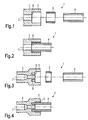
- Fig. 1 the arrangement 1 according to the invention in a sectional view before assembly, ie before assembly, shown.
- a coupling device 2 a cylinder-shaped adhesive element 3 and a tubular element 4, which is designed here as a rigid pipeline.
- flexible lines are conceivable.
- the coupling device 2 and the tubular element 4 made of plastic, z. B. a polyolefin, such as. B. polypropylene.
- the coupling device and / or the tubular element may be made of metal or an elastomer.
- multilayer pipes or hoses are conceivable.
- the adhesive consists of a heat-fusible plastic, which is pressed into a cylindrical-shaped adhesive element.
- the adhesive element can also be produced by injection molding or by extrusion. Alternatively, the adhesive element may also be designed in several parts, for. B. of two half-shells or multiple segments. Furthermore, metal particles may be present in the adhesive element, in particular to promote inductive heating. Otherwise, the adhesive is heat-fusible adhesive commonly used in the art.
- the adhesive element may also comprise electrically conductive particles through which the adhesive is electrically conductive.
- the coupling element and the pipe may be formed electrically conductive, so that the entire arrangement is electrically conductive.
- the coupling device 2 has a tubular portion 5, to which a radially extending abutment portion 6 attaches. Concentric with the tubular portion, a line section 7 is also provided, which opens into the contact section 6, so that a fluid can be conveyed through the coupling device.
- the inner diameter of the tubular portion is dimensioned such that it is slightly larger than the outer diameter of the cylindrical annular adhesive element.
- the coupling device and an adhesive element can be easily interlocked.
- the tubular element is designed such that its outer diameter is slightly smaller than the inner diameter of the adhesive element, so that also the tubular element and the adhesive member can be easily interlocked.
- the adhesive element is melted in a next step, so that the adhesive bond between the tubular element and the coupling device is produced.
- the items namely a coupling device, adhesive member and tubular member are assembled, and it is irrelevant whether initially the adhesive member or the tubular member is introduced into the tubular portion of the coupling device. If only the tubular element to be introduced, it is advantageous if the adhesive element is formed in several parts, for. B. by two half shells.
- the adhesive element is formed in several parts, for. B. by two half shells.
- heat can now be supplied to the adhesive element so that the adhesive element melts and produces an adhesive bond between the tubular element and the coupling device. Since a clearance exists between the adhesive element, the coupling device and the tubular element, alignment of the tubular element with respect to the coupling device can first be carried out. In this way tolerances can be compensated.
- the assembly 1 can be delivered prefabricated and the coupling device and the tubular element are brought into their final installation position. By subsequent bonding a stress-free connection between the coupling device and tubular element can be ensured.
- a coupling stub 8 is additionally provided, on which the tubular element is pushed.
- the coupling stub 8 is formed by an annular groove formed in the abutment portion 6. The dimensions of the groove can be chosen so that the tubular element can be easily inserted. The assembly and bonding are then carried out in the same manner as in the first embodiment.
- the adhesive member is slightly different in design. It also has a radially inwardly extending portion 9, with which the adhesive element is brought into contact with the contact portion 6 of the coupling device 2.
- the tubular element is located on the front side on the radially inwardly extending portion 9. In this way, an end-side bonding of the tubular element with the coupling device is ensured.
- FIG. 7 shows a fourth embodiment after assembly. There, too, the same components are identified by the same reference numerals. In contrast to the third embodiment, this embodiment additionally has a coupling stub 8.
Landscapes
- Engineering & Computer Science (AREA)
- Mechanical Engineering (AREA)
- General Engineering & Computer Science (AREA)
- Standing Axle, Rod, Or Tube Structures Coupled By Welding, Adhesion, Or Deposition (AREA)
Abstract
Die Erfindung bezieht sich auf eine Anordnung (1) mit einem rohrförmigen Element (4), vorzugsweise einer Rohrleitung oder einem Schlauch, und einer Kupplungseinrichtung (2), die einen rohrförmigen Abschnitt (5) aufweist, dessen Innendurchmesser größer als der Außendurchmesser des rohrförmigen Elements (4) ist, und bei der das rohrförmige Element (4) abschnittsweise in dem rohrförmigen Abschnitt (5) angeordnet ist. Um eine derartige Anordnung (1) zu verbessern ist erfindungsgemäß vorgesehen, dass zwischen dem rohrförmigen Element (4) und dem rohrförmigen Abschnitt (5) ein vorgefertigtes vorzugsweise ringförmiges Klebeelement (3) im Wesentlichen aus aufschmelzbaren Klebstoff angeordnet ist.
Description
- Die vorliegende Erfindung bezieht sich auf eine Anordnung mit einem rohrförmigen Ele-ment, vorzugsweise einer Rohrleitung oder einem Schlauch, und einer Kupplungseinrichtung, die einen rohrförmigen Abschnitt aufweist, dessen einer Innendurchmesser größer als der Außendurchmesser des rohrförmigen Elements ist und bei der das rohrförmige Element abschnittsweise in dem rohrförmigen Abschnitt angeordnet ist.
- Eine derartige Anordnung ist z. B. aus der
DE 19945218 bekannt. Dort ist ein Kupplungsteil beschrieben, das einen äußeren rohrförmigen Abschnitt und einen inneren Kupplungsstutzen aufweist. Zwischen dem äußeren rohrförmigen Abschnitt und dem Kupplungsstutzen wird ein Raum gebildet, in dem konzentrisch ein Endabschnitt einer Fluidleitung angeordnet ist. Die Fluidleitung ist auf den Kupplungsstutzen aufgeschoben. Um eine feste Verbindung zwischen der Rohrleitung und dem Kupplungsteil zu erzeugen, ist vorgesehen, vor dem Aufschieben der Rohrleitung auf den Rohrstutzen, zunächst einen Ring aus einem festen verpressten, aufschmelzbaren Klebstoff einzubringen, der im Wesentlichen den Raum zwischen dem äußeren rohrförmigen Abschnitt und dem Kupplungsstutzen auffüllt. Zur Montage der Rohrleitung im Kupplungsteil wird der Klebstoff aufgeschmolzen, während die Rohrleitung auf den Kupplungsstutzen aufgeschoben wird. Bei der Montage stößt dabei das stirnseitige Ende der Rohrleitung auf den Klebstoff und verdrängt diesen, so dass nach vollständig auf den Kupplungsstutzen aufgeschobene Rohrleitung der Klebstoff in den verbleibenden Spalt zwischen Rohrleitung und dem äußeren rohrförmigen Abschnitt gedrängt wird. - Durch das Verdrängen des Klebstoffs während des Einführens der Rohrleitung bei gleichzeitiger Erwärmung des Klebstoffs führt zu heftigen Bewegungen innerhalb des Klebstoffs. Darüber hinaus kann nicht ausgeschlossen werden, dass je nach Lage der Toleranzen von Rohrleitung, Kupplungsstutzen und dem rohrförmigen äußeren Abschnitt und der sich daraus ergebenden Druckverhältnisse Klebstoff aus der Verbindung unter Druck herausfließt. Ebenso sind Lufteinschlüsse zu befürchten.
- Die Aufgabe der Erfindung ist daher, eine Anordnung der eingangs genannten Art derart zu verbessern, dass die Nachteile aus dem Stand der Technik überwunden werden.
- Die Aufgabe wird erfindungsgemäß dadurch gelöst, dass zwischen dem rohrförmigen Element und dem rohrförmigen Abschnitt ein vorgeformtes vorzugsweise ringförmiges Klebeelement im Wesentlichen aus aufschmelzbaren, Klebstoff angeordnet ist.
- Diese Lösung ist einfach und hat den Vorteil, dass zunächst die Rohrleitung in den Raum innerhalb des rohrförmigen Abschnitts eingebracht wird und das ringförmige Klebeelement entweder vor dem Einbringen der Rohrleitung oder nach dem Einbringen der Rohrleitung zwischen Rohrleitung und dem rohrförmigen Abschnitt angeordnet wird. Durch diese Anordnung ist nunmehr möglich, den Klebstoff aufzuschmelzen in einem Zustand, wo die Bauteile bereits zueinander ausgerichtet sind. Auf diese Weise werden heftige Bewegungen des Klebstoffs während des Verbindungsvorganges zwischen Rohrleitung und Kupplungseinrichtung vermieden. Dadurch, dass das ringförmige Klebeelement aus aufschmelzbarem Klebstoff besteht, ist es auch möglich, die Einzelteile, nämlich Rohrleitung, Kupplungseinrichtung und Klebeelement, vorzukonfektionieren und die eigentliche Verbindung erst dann vorzunehmen, wenn die endgültige Einbausituation vorliegt, und z. B. die Teile gegeneinander ausgerichtet sind. Auf diese Weise können insbesondere radiale Toleranzen ausgeglichen werden, die sich aufgrund der tatsächlichen Einbausituation ergeben. Der Klebstoff kann sich dann an die jeweilige Einbausituation problemlos anpassen.
- In einer vorteilhaften Weiterbildung kann das Klebeelement aus gepresstem Klebstoff bestehen. Dadurch lässt sich das Klebeelement maßgenau herstellen und einfach montieren.
- In einer vorteilhaften Weiterbildung der Erfindung kann die Kupplungseinrichtung einen sich im Wesentlichen radial erstreckenden Anlageabschnitt aufweisen, an dem das Klebeelement in Achsrichtung des rohrförmigen Abschnitts anliegt. Dadurch lässt sich ein Kleberaum definieren, der durch den rohrförmigen Abschnitt und den radial sich erstreckenden Abschnitt begrenzt wird. Auch kann dadurch eine Montage vereinfacht werden.
- Das rohrförmige Element kann dann an dem Anlageadschnitt anliegen, um die Positionierung vorzunehmen.
- Zudem kann es sich als vorteilhaft erweisen, wenn der Innendurchmesser des rohrförmigen Abschnitts geringfügig größer als der Außendurchmesser des Klebeelements ist. Dadurch kann die Montage des Klebeelements vereinfacht werden. Dabei kann es sich ebenfalls als günstig erweisen, wenn der Innendurchmesser des Klebeelements geringfügig größer als der Außendurchmesser des rohrförmigen Elements ist. Auch dadurch kann erreicht werden, dass das Klebeelement problemlos in den Raum zwischen dem rohrförmigen Element und dem rohrförmigen Abschnitt eingebracht werden kann.
- Ferner kann es sich dabei als vorteilhaft erweisen, wenn das Klebeelement im Wesentlichen zylinderringförmig ist. Auch dadurch kann die Montage erleichtert werden.
- Eine Vereinfachung der Montage lässt sich auch erzielen, wenn das Klebeelement einen wärmeschmelzbaren Klebstoff aufweist.
- Um eine weitere Verbesserung der Verklebung zwischen Kupplungseinrichtung und rohrförmigen Element zu erhalten, kann vorgesehen sein, dass das Klebeelement einen sich zumindest abschnittsweise radial nach innen erstreckenden Abschnitt aufweist. Dann kann es sich als günstig erweisen, wenn das rohrförmige Element stirnseitig wenigstens abschnittsweise an dem sich radial nach innen erstreckenden Abschnitt anliegt. Bei dieser Ausführungsform ist es jedoch erforderlich, dass zunächst das Klebeelement montiert wird, bevor das rohrförmige Element eingebracht wird. Andererseits kann der stirnseitige Kontakt des rohrförmigen Elements mit dem Klebstoff und darüber hinaus der Kontakt zwischen Klebstoff und Kupplungseinrichtung die Verklebung verbessern.
- In einer vorteilhaften Weiterbildung kann die Kupplungseinrichtung einen Kupplungsstutzen aufweisen, der sich abschnittsweise in das rohrförmige Element hinein erstreckt. Auch dadurch lässt sich die Verbindung zwischen der Kupplungseinrichtung und dem rohrförmigen Element verbessern.
- Der kupplungsstutzen kann dabei durch eine in dem sich radial erstreckenden Abschnitt der Kupplungseinrichtung angeordnete ringförmig verlaufende Nut gebildet sein. Auf diese Weise lässt sich einfach und kostengünstig ein Kupplungsstutzen verwirklichen.
- Um ein Herausfließen des Klebstoffs aus der Verbindung zwischen Kupplungseinrichtung und rohrförmigen Element zu verhindern, kann die axiale Länge des Klebeelements geringer als die axiale Länge des rohrförmigen Abschnitts sein.
- Weiter kann es sich als vorteilhaft erweisen, wenn das Klebeelement und das rohrförmige Element aus Kunststoff bestehen bzw. Kunststoff, vorzugsweise einen polymeren Kunststoff aufweisen. Dadurch lässt sich eine sehr stabile Klebeverbindung erreichen. Besonders vorteilhaft kann es dabei sein, wenn das Klebeelement und das rohrförmige Element aus dem gleichen Kunststoff bestehen. Ebenso kann es sich als günstig erweisen, wenn das Klebeelement, das rohrförmig Element und das Kupplungselement zumindest bereichsweise den gleichen Kunststoff aufweisen.
- Ferner kann der Klebstoff elektrisch leitende Partikel aufweisen. Dadurch kann der Klebstoff z. B. durch Induktion aufgeschmolzen werden. Darüber hinaus ist es denkbar, auch das Kupplungselement und / oder die Rohrleitung, wie auch das Klebeelement elektrisch leitend auszuführen. Auf diese Weise kann eine elektrisch leitende Verbindung zwischen der Kupplungseinrichtung, dem rohrförmigen Element und dem Klebstoff nach der Montage gewährleistet werden.
- Weiterhin wird ein Verfahren zum Herstellen einer Verbindung einer Anordnung nach einem der vorangegangenen Ansprüche beansprucht, bei dem zunächst das gepressten aufschmelzbaren Klebstoff aufweisenden Klebeelement und das rohrförmige Element in den rohrförmigen Abschnitt eingebracht und anschließend der Klebstoff aufgeschmolzen wird.
- Durch dieses Verfahren lassen sich, wie auch durch Anspruch 1 die erfindungsgemäßen Vorteile erzielen. Insbesondere ermöglicht diese Vorgehensweise ein endgültiges Verbinden von rohrförmigen Element und Kupplungseinrichtung in der tatsächlichen Einbausituation und dadurch den Ausgleich von radialen Toleranzen der Einbaulagen von Kuoolunoseinrichtuna und rohrförmioem Element.
- Zudem kann es sich als günstig erweisen, wenn das rohrförmige Element und die Kupplungseinrichtung vor dem Aufschmelzen des Klebstoffs zueinander ausgerichtet werden.
- Weiterhin kann es sich als günstig erweisen, wenn während des Aufschmelzens das rohrförmige Element im Wesentlichen senkrecht nach oben ragt. Dadurch kann ein gleichmäßiges Herumfließen des Klebstoffs um das rohrförmige Element erreicht werden.
- Ferner kann es sich als vorteilhaft erweisen, wenn vor dem Aufschieben des Klebeelements das rohrförmige Element auf den Kupplungsstutzen aufgesteckt wird.
- Nachfolgend wird die Wirkungsfunktionsweise der Erfindung anhand von Ausführungsbeispielen näher erläutert.
- Es zeigen:
- Fig. 1
- die erfindungsgemäße Anordnung vor der Montage;
- Fig. 2
- die erfindungsgemäße Anordnung aus Fig. 1 nach der Montage;
- Fig. 3
- eine zweite Ausführungsform der erfindungsgemäßen Anordnung vor der Mon-tage;
- Fig. 4
- die Anordnung aus Fig. 3 nach der Montage;
- Fig. 5
- eine dritte Ausführungsform der erfindungsgemäßen Anordnung vor der Monta-ge;
- Fig. 6
- die Anordnung aus Fig. 5 nach der Montage und
- Fig. 7
- eine vierte Ausführungsform der erfindungsgemäßen Anordnung nach der Mon-tage.
- Fig. 1 ist die erfindungsgemäße Anordnung 1 in einer Schnittansicht vor der Montage, also vor dem Zusammensetzen, dargestellt. Im Einzelnen werden gezeigt: eine Kupplungseinrichtung 2, ein zylinderringförmiges Klebeelement 3 und ein rohrförmiges Element 4, das hier als starre Rohrleitung ausgebildet ist. Alternativ sind auch flexible Leitungen denkbar. Im vorliegenden Ausführungsbeispiel besteht die Kupplungseinrichtung 2 und das rohrförmige Element 4 aus Kunststoff, z. B. einem Polyolefin, wie z. B. Polypropylen. Alternativ sind auch andere Werkstoffe denkbar. Beispielsweise kann die Kupplungseinrichtung und/oder das rohrförmige Element aus Metall oder einem Elastomer bestehen. Ferner sind auch mehrschichtige Rohrleitungen oder Schläuche denkbar.
- Das Klebestoff besteht aus einem wärmeaufschmelzbaren Kunststoff, der zu einem zylinderringförmigen Klebeelement verpresst ist. Das Klebeelement kann auch im Spritzgießverfahren oder durch Extrusion hergestellt sein. Alternativ kann das Klebeelement auch mehrteilig ausgebildet sein, z. B. aus zwei Halbschalen oder mehreren Segmenten. Ferner können Metallpartikel im Klebeelement vorhanden sein, um insbesondere eine induktive Erwärmung zu fördern. Anderweitig handelt es sich bei dem Klebstoff um im Stand der Technik gängigen wärmeaufschmelzbaren Klebstoff.
- Das Klebeelement kann zudem auch elektrisch leitfähige Partikel aufweisen, durch die der Klebstoff elektrisch leitfähig ist. Darüber hinaus kann auch das Kupplungselement und die Rohrleitung elektrisch leitfähig ausgebildet sein, so dass die gesamte Anordnung elektrisch leitfähig ist.
- Bei der ersten Ausführungsform verfügt die Kupplungseinrichtung 2 über einen rohrförmigen Abschnitt 5, an den sich ein radial erstreckender Anlageabschnitt 6 anfügt. Konzentrisch zum rohrförmigen Abschnitt ist darüber hinaus ein Leitungsabschnitt 7 vorgesehen, der in den Anlageabschnitt 6 mündet, so dass ein Fluid durch die Kupplungseinrichtung hindurch gefördert werden kann.
- Der Innendurchmesser des rohrförmigen Abschnitts ist dabei so bemessen, dass er geringfügig größer als der Außendurchmesser des zylinderringförmigen Klebeelements ist. Dadurch können Kupplungseinrichtung und ein Klebeelement problemlos ineinander gesetzt werden. Weiterhin ist das rohrförmige Element derart gestaltet, dass sein Außendurchmesser geringfügig kleiner als der Innendurchmesser des Klebeelements ist, so dass auch das rohrförmige Element und das Klebeelement problemlos ineinander gesetzt werden können.
- Im montierten Zustand, also wenn Kupplungseinrichtung, Klebeelement und rohrförmiges Element entsprechend Fig. 2 ineinandergesetzt sind, erfolgt in einem nächsten Schritt das Aufschmelzen des Klebeelements, so dass die Klebeverbindung zwischen dem rohrförmigen Element und der Kupplungseinrichtung hergestellt wird.
- Nachfolgend wird die Wirkungs- und Funktionsweise der Erfindung näher erläutert:
- Zunächst werden die Einzelteile, nämliche eine Kupplungseinrichtung, Klebeelement und rohrförmiges Element zusammengesetzt, wobei es unerheblich ist, ob zunächst das Klebeelement oder das rohrförmige Element in dem rohrförmigen Abschnitt der Kupplungseinrichtung eingebracht wird. Wenn erst das rohrförmige Element eingebracht werden soll, ist es günstig, wenn das Klebeelement mehrteilig ausgebildet ist, z. B. durch zwei Halbschalen. Im zusammengesetzten Zustand nimmt die Anordnung aus Kupplungseinrichtung, Klebeelement und rohrförmigen Element die in Fig. 2 dargestellte Konfiguration ein. In einem nächsten Schritt kann nunmehr dem Klebeelement Wärme zugeführt werden, so dass das Klebeelement aufschmilzt und eine Klebeverbindung zwischen dem rohrförmigen Element und der Kupplungseinrichtung herstellt. Da zwischen Klebeelement, Kupplungseinrichtung und rohrförmigen Element ein Spiel vorliegt, kann zunächst ein Ausrichten von dem rohrförmigen Element gegenüber der Kupplungseinrichtung durchgeführt werden. Auf diese Weise können Toleranzen ausgeglichen werden. So kann die Anordnung 1 vorkonfektioniert angeliefert werden und die Kupplungseinrichtung und das rohrförmige Element in ihre endgültige Einbaulage gebracht werden. Durch das nachträgliche Verkleben kann eine spannungsfreie Verbindung zwischen Kupplungseinrichtung und rohrförmigen Element sichergestellt werden.
- Nachfolgend wird eine zweite Ausführungsform der Erfindung erläutert. Um Wiederholungen zu vermeiden, wird jedoch nur auf die Unterschiede zur ersten Ausführungsform hingewiesen. Insbesondere erhalten die gleichen Bauteile auch die gleichen Bezugszeichen.
- Bei der zweiten Ausführungsform ist zusätzlich ein Kupplungsstutzen 8 vorgesehen, auf den das rohrförmige Element aufgeschoben wird. Der Kupplungsstutzen 8 wird durch eine im Anlageabschnitt 6 ausgebildete ringförmige Nut gebildet. Die Abmessungen der Nut können dabei so gewählt werden, dass sich das rohrförmige Element problemlos einstecken lässt. Der Zusammenbau und das Verkleben erfolgen anschließend in gleicher Weise wie bei der ersten Ausführungsform.
- Nachfolgend wird die dritte Ausführungsform der Erfindung erläutert. Auch bei dieser Ausführungsform werden nur die Unterschiede zur ersten Ausführungsform aufgezeigt. Bei der dritten Ausführungsform ist das Klebeelement geringfügig anders gestaltet. Es verfügt zusätzlich über einen sich radial nach innen erstreckenden Abschnitt 9, mit dem das Klebeelement in Anlage mit dem Anlageabschnitt 6 der Kupplungseinrichtung 2 gebracht wird. Zusätzlich liegt das rohrförmige Element stirnseitig an dem radial nach innen sich erstreckenden Abschnitt 9 an. Auf diese Weise wird auch eine stirnseitige Verklebung des rohrförmigen Elements mit der Kupplungseinrichtung gewährleistet.
- In Figur 7 ist zudem eine vierte Ausführungsform nach der Montage dargestellt. Auch dort sind die gleichen Bauteile mit den gleichen Bezugszeichen gekennzeichnet. Im Unterschied zur dritten Ausführungsform verfügt diese Ausführungsform zusätzlich über einen Kupplungsstutzen 8.
Claims (20)
- Anordnung mit einem rohrförmigen Element, vorzugsweise einer Rohrleitung oder einem Schlauch, und einer Kupplungseinrichtung (2), die einen rohrförmigen Abschnitt (5) aufweist, dessen Innendurchmesser größer als der Außendurchmesser des rohrförmigen Elements ist, und bei der das rohrförmige Element abschnittsweise in dem rohrförmigen Abschnitt angeordnet ist, dadurch gekennzeichnet, dass zwischen dem rohrförmigen Element (4) und dem rohrförmigen Abschnitt (5) ein vorgefertigtes vorzugsweise ringförmiges Klebeelement (3) im Wesentlichen aus aufschmelzbaren Klebstoff angeordnet ist.
- Anordnung nach Anspruch 1, dadurch gekennzeichnet, dass das Klebeelement aus gepresstem Klebstoff besteht.
- Anordnung nach Anspruch 1 oder 2, dadurch gekennzeichnet, dass die Kupplungseinrichtung (2) einen sich im Wesentlichen radial erstreckenden Anlageabschnitt (6) aufweist, an dem das Klebeelement in Achsrichtung des rohrförmigen Abschnitts anliegt.
- Anordnung nach einem der vorangegangenen Ansprüche, dadurch gekennzeichnet, dass der Innendurchmesser des rohrförmigen Abschnitts geringfügig größer als der Außendurchmesser des Klebeelements ist.
- Anordnung nach einem der vorangegangenen Ansprüche, dadurch gekennzeichnet, dass der Innendurchmesser des Klebeelements geringfügig größer als der Außendurchmesser des rohrförmigen Elements ist.
- Anordnung nach einem der vorangegangenen Ansprüche, dadurch gekennzeichnet, dass das Klebeelement im Wesentlichen zylinderringförmig ist.
- Anordnung nach einem der vorangegangenen Ansprüche, dadurch gekennzeichnet, dass das rohrförmige Element im Wesentlichen konzentrisch zum rohrförmigen Abschnitt angeordnet ist.
- Anordnung nach einem der vorangegangenen Ansprüche, dadurch gekennzeichnet, dass das Klebeelement einen sich zumindest abschnittsweise radial nach innen erstreckenden Abschnitt aufweist.
- Anordnung nach einem der vorangegangenen Ansprüche, dadurch gekennzeichnet, dass das rohrförmige Element stirnseitig wenigstens abschnittsweise einen sich radial nach innen erstreckenden Abschnitt aufweist.
- Anordnung nach einem der vorangegangenen Ansprüche, dadurch gekennzeichnet, dass das rohrförmige Element stirnseitig wenigstens abschnittsweise an dem sich radial nach innen erstreckenden Abschnitt anliegt.
- Anordnung nach einem der vorangegangenen Ansprüche, dadurch gekennzeichnet, dass die Kupplungseinrichtung einen Kupplungsstutzen aufweist, der sich abschnittsweise in das rohrförmige Element hinein erstreckt.
- Anordnung nach einem der vorangegangenen Ansprüche, dadurch gekennzeichnet, dass der Kupplungsstutzen durch eine sich in dem radial erstreckenden Abschnitt der Kupplungseinrichtung angeordnete ringförmig verlaufende Nut gebildet wird.
- Anordnung nach einem der vorangegangenen Ansprüche, dadurch gekennzeichnet, dass die axiale Länge des Klebeelements geringer als die axiale Länge des ringförmigen Abschnitts ist.
- Anordnung nach einem der vorangegangenen Ansprüche, dadurch gekennzeichnet, dass das Kupplungselement Kunststoff, vorzugsweise polymeren Kunststoff aufweisen.
- Anordnung nach einem der vorangegangenen Ansprüche, dadurch gekennzeichnet, dass das rohrförmige Element Kunststoff, vorzugsweise polymeren Kunststoff aufweist.
- Anordnung nach einem der vorangegangenen Ansprüche, dadurch gekennzeichnet, dass der Klebstoff elektrisch leitende Partikel aufweist.
- Verfahren zum Herstellen einer Verbindung einer Anordnung nach einem der vorangegangenen Ansprüche bei dem zunächst das gepresste Klebeelement und das rohrförmige Element in den rohrförmigen Abschnitt eingebracht und anschließend der Klebstoff aufgeschmolzen wird.
- Verfahren nach Anspruch 17, dadurch gekennzeichnet, dass das rohrförmige Element und die Kupplungseinrichtung vor dem Aufschmelzen des Klebstoffs zueinander ausgerichtet werden.
- Verfahren nach Anspruch 17 oder 18, dadurch gekennzeichnet, dass während des Aufschmelzens des Kunststoffs das rohrförmige Element im Wesentlichen senkrecht nach oben ragt.
- Verfahren nach einem der Ansprüche 17 bis 19, dadurch gekennzeichnet, dass vor dem Aufschmelzen des Klebeelements das rohrförmige Element auf den Kupplungsstutzen aufgesteckt wird.
Applications Claiming Priority (1)
| Application Number | Priority Date | Filing Date | Title |
|---|---|---|---|
| DE102005013859A DE102005013859A1 (de) | 2005-03-24 | 2005-03-24 | Anordnung mit einem rohrförmigen Element |
Publications (1)
| Publication Number | Publication Date |
|---|---|
| EP1705414A1 true EP1705414A1 (de) | 2006-09-27 |
Family
ID=36579215
Family Applications (1)
| Application Number | Title | Priority Date | Filing Date |
|---|---|---|---|
| EP05026627A Withdrawn EP1705414A1 (de) | 2005-03-24 | 2005-12-06 | Anordnung mit einem rohrförmigen Element |
Country Status (3)
| Country | Link |
|---|---|
| US (1) | US20060214418A1 (de) |
| EP (1) | EP1705414A1 (de) |
| DE (1) | DE102005013859A1 (de) |
Cited By (3)
| Publication number | Priority date | Publication date | Assignee | Title |
|---|---|---|---|---|
| WO2007088072A1 (de) * | 2006-01-31 | 2007-08-09 | Donald Herbst | Verbindung zwischen der stirnseite eines kunststoffrohres und einem kunstoffkörper |
| WO2010083942A1 (fr) * | 2009-01-26 | 2010-07-29 | A. Raymond Et Cie | Dispositif de raccordement de conduits plastiques |
| EP2673022A4 (de) * | 2011-02-11 | 2014-09-03 | Carefusion 303 Inc | Armatur und montageverfahren dafür |
Families Citing this family (16)
| Publication number | Priority date | Publication date | Assignee | Title |
|---|---|---|---|---|
| TWM271973U (en) * | 2004-12-24 | 2005-08-01 | Ching-Wen Chen | Improved connection structure of a metal connector |
| US7300536B1 (en) * | 2006-05-09 | 2007-11-27 | Gm Global Technology Operations, Inc. | Method for attaching intersecting tubes |
| DE102007040452A1 (de) * | 2007-08-24 | 2009-03-19 | Fraunhofer-Gesellschaft zur Förderung der angewandten Forschung e.V. | Verfahren zum Verbinden von Rohren sowie Rohr mit profiliertem Stirnende |
| DE102007041377A1 (de) * | 2007-08-31 | 2009-03-05 | Code Consulting | Kunststoff-Metall-Verbundrohrsystem |
| DE202007016637U1 (de) | 2007-11-27 | 2009-04-09 | Tube Technology Systems Ag | Rohrverbindung |
| DE102008023276A1 (de) * | 2008-05-13 | 2009-11-19 | Henkel Ag & Co. Kgaa | Verbinden von Rohren mit thermisch härtbaren Klebstoffen |
| KR101525564B1 (ko) * | 2012-12-04 | 2015-06-03 | 주식회사 로도에이치 | 파이프 연결장치 및 파이프 연결방법 |
| DE102014018147B4 (de) * | 2014-12-08 | 2016-06-30 | Audi Ag | Vorrichtung zur Verbindung einer Leitung mit einem Schlauch in einer Klimaanlage |
| DE102018208268A1 (de) * | 2018-05-25 | 2019-11-28 | Zf Friedrichshafen Ag | Verfahren zum Herstellen einer Klebeverbindung sowie eine Achstrebe für ein Fahrzeug |
| JP2020041560A (ja) * | 2018-09-07 | 2020-03-19 | 亮助 土場 | 継ぎ手 |
| WO2020065495A1 (en) * | 2018-09-28 | 2020-04-02 | 3M Innovative Properties Company | Tubular elements with adhesive joint, method of joining tubular elements thereof |
| DE102019133972B3 (de) * | 2019-12-11 | 2021-06-17 | Eugen Forschner Gmbh | Schlauch-konnektor-verbindung |
| CN111396684B (zh) * | 2020-04-27 | 2021-08-31 | 谢娟 | 一种电热密封式管道密封装置 |
| CN112178326A (zh) * | 2020-09-30 | 2021-01-05 | 中国石油大学(华东) | 一种热熔机械挤压式柔性管接头 |
| US20220120362A1 (en) * | 2020-10-21 | 2022-04-21 | David Romero | Apparatus and method for pipe repair |
| US20240360925A1 (en) * | 2022-04-22 | 2024-10-31 | Taisei Kogyo Co., Ltd. | Manufacturing method of tube-attached coupling structure and tube-attached coupling structure |
Citations (8)
| Publication number | Priority date | Publication date | Assignee | Title |
|---|---|---|---|---|
| GB695027A (en) * | 1950-08-15 | 1953-08-05 | Raymond James Mitchell | Improvements in or relating to connecting means for pipes and tubes |
| EP0343757A2 (de) * | 1984-04-04 | 1989-11-29 | RAYCHEM CORPORATION (a Delaware corporation) | Verfahren zum Verbinden von Substraten |
| US4896904A (en) * | 1983-11-08 | 1990-01-30 | Rachem Limited | Heat shrinkable device with adhesive barrier for connecting elongate objects |
| JPH08277988A (ja) * | 1995-04-06 | 1996-10-22 | C I Kasei Co Ltd | エチレン系樹脂パイプの接合方法およびその接合構造 |
| EP0882927A1 (de) * | 1997-05-09 | 1998-12-09 | Nupi S.p.A. | Rohrverbindung mit thermoelektrischer Haftung |
| DE19945218C1 (de) * | 1999-09-21 | 2001-03-22 | Raymond A & Cie | Rohrförmiges Kupplungsteil und Verfahren zur Herstellung einer Klebeverbindung mit einer Fluidleitung |
| US20030192641A1 (en) * | 2002-04-15 | 2003-10-16 | Espejo Gilbert-Bobby A. | Method and apparatus of assembling a fluid flow conduit assembly of dissimilar plastics |
| EP1505328A2 (de) * | 2003-08-08 | 2005-02-09 | Veritas Ag | Kupplung zum Verbinden von Leitungen |
Family Cites Families (2)
| Publication number | Priority date | Publication date | Assignee | Title |
|---|---|---|---|---|
| DE1086426B (de) * | 1955-09-09 | 1960-08-04 | Mannesmann Ag | Verfahren zum Verschweissen von ineinandergreifenden Formteilen aus thermoplastischem Kunststoff |
| US5150922A (en) * | 1989-01-11 | 1992-09-29 | Osaka Gas Co., Ltd. | Electrofusion joint and hot water supply header using the same |
-
2005
- 2005-03-24 DE DE102005013859A patent/DE102005013859A1/de not_active Ceased
- 2005-12-06 EP EP05026627A patent/EP1705414A1/de not_active Withdrawn
-
2006
- 2006-03-22 US US11/385,686 patent/US20060214418A1/en not_active Abandoned
Patent Citations (8)
| Publication number | Priority date | Publication date | Assignee | Title |
|---|---|---|---|---|
| GB695027A (en) * | 1950-08-15 | 1953-08-05 | Raymond James Mitchell | Improvements in or relating to connecting means for pipes and tubes |
| US4896904A (en) * | 1983-11-08 | 1990-01-30 | Rachem Limited | Heat shrinkable device with adhesive barrier for connecting elongate objects |
| EP0343757A2 (de) * | 1984-04-04 | 1989-11-29 | RAYCHEM CORPORATION (a Delaware corporation) | Verfahren zum Verbinden von Substraten |
| JPH08277988A (ja) * | 1995-04-06 | 1996-10-22 | C I Kasei Co Ltd | エチレン系樹脂パイプの接合方法およびその接合構造 |
| EP0882927A1 (de) * | 1997-05-09 | 1998-12-09 | Nupi S.p.A. | Rohrverbindung mit thermoelektrischer Haftung |
| DE19945218C1 (de) * | 1999-09-21 | 2001-03-22 | Raymond A & Cie | Rohrförmiges Kupplungsteil und Verfahren zur Herstellung einer Klebeverbindung mit einer Fluidleitung |
| US20030192641A1 (en) * | 2002-04-15 | 2003-10-16 | Espejo Gilbert-Bobby A. | Method and apparatus of assembling a fluid flow conduit assembly of dissimilar plastics |
| EP1505328A2 (de) * | 2003-08-08 | 2005-02-09 | Veritas Ag | Kupplung zum Verbinden von Leitungen |
Non-Patent Citations (1)
| Title |
|---|
| PATENT ABSTRACTS OF JAPAN vol. 1997, no. 02 28 February 1997 (1997-02-28) * |
Cited By (5)
| Publication number | Priority date | Publication date | Assignee | Title |
|---|---|---|---|---|
| WO2007088072A1 (de) * | 2006-01-31 | 2007-08-09 | Donald Herbst | Verbindung zwischen der stirnseite eines kunststoffrohres und einem kunstoffkörper |
| WO2010083942A1 (fr) * | 2009-01-26 | 2010-07-29 | A. Raymond Et Cie | Dispositif de raccordement de conduits plastiques |
| FR2941512A1 (fr) * | 2009-01-26 | 2010-07-30 | Raymond A & Cie | Dispositif de raccordement de conduits plastiques. |
| EP2673022A4 (de) * | 2011-02-11 | 2014-09-03 | Carefusion 303 Inc | Armatur und montageverfahren dafür |
| US9339640B2 (en) | 2011-02-11 | 2016-05-17 | Carefusion 303, Inc. | Connector for multiple sizes of tubing |
Also Published As
| Publication number | Publication date |
|---|---|
| US20060214418A1 (en) | 2006-09-28 |
| DE102005013859A1 (de) | 2006-10-05 |
Similar Documents
| Publication | Publication Date | Title |
|---|---|---|
| DE102005013859A1 (de) | Anordnung mit einem rohrförmigen Element | |
| DE60023502T2 (de) | Schweissmuffe mit verstärkung für kunststoffrohre | |
| EP0221395B1 (de) | Flanschverbindung für faserverstärkte Kunststoffrohrteile | |
| DE102007047495B4 (de) | Wellrohrschlauchleitung sowie Verfahren zu deren Herstellung | |
| EP1756464B1 (de) | Verbindungsanordnung, insbesondere zum kraftschlüssigen anbinden von mindestens einem faserverbund-bauteil an ein weiteres bauteil | |
| DE102013207206A1 (de) | Rohrelement mit Composite-Rohr und Metallverbinder | |
| DE4307514C2 (de) | Verbinder für dünne Rohre | |
| EP0835374B1 (de) | Ansaugeinrichtung aus thermoplastischem kunststoff | |
| DE102008006068B3 (de) | Schweißsystem für mehrschichtige Verbundrohre aus Kunststoff und Metall | |
| EP1943448A1 (de) | Fluidleitung und verfahren zu ihrer herstellung | |
| EP3894711B1 (de) | Spreizdübel | |
| EP2025987A2 (de) | Anschluss- oder Verbindungsteil für eine Wellrohr- oder Wellschlauchleitung | |
| DE102006024767B4 (de) | Verfahren und Vorrichtung zum Verbinden eines Kunststoffdeckels mit einem Metallgehäuse | |
| EP3450812B1 (de) | Leitungskupplung und behälter hiermit | |
| DE4214279C2 (de) | Verbindungselement zum Verschweißen von Rohren | |
| DE102005014339B3 (de) | Kunststoffrohr und Verfahren und Vorrichtung zum Fügen zweier Kunststoffrohre | |
| DE19538195A1 (de) | Geteilter Bowdenzug | |
| DE3937888C2 (de) | ||
| WO2006111221A1 (de) | Kunststoffbauteil mit metalleinsatz und verfahren zu dessen herstellung | |
| DE29721224U1 (de) | Leitungsverbindung | |
| DE10334369B3 (de) | Armierter mehrschichtiger Hydraulikschlauch mit angeschlossenem Verbinder | |
| DE102015108083A1 (de) | Flanschverbindung für Bauteile aus Kunststoff, insbesondere für rohrförmige Bauteile aus Kunststoff | |
| DE2206210C2 (de) | Verbindung von rohrförmigen, elektrisch gegeneinander isolierten Bau- und/oder Leitungsteilen | |
| DE19961047C2 (de) | Verfahren zum Anschluß eines Mehrschichtverbundrohres und Verbindungsstelle sowie Bauteil zur Erwärmung der Materialschichten eines Mehrschichtverbundrohres | |
| DE10160379B4 (de) | Kupplung für Rohre und Verfahren zu ihrem Aufbau |
Legal Events
| Date | Code | Title | Description |
|---|---|---|---|
| PUAI | Public reference made under article 153(3) epc to a published international application that has entered the european phase |
Free format text: ORIGINAL CODE: 0009012 |
|
| AK | Designated contracting states |
Kind code of ref document: A1 Designated state(s): AT BE BG CH CY CZ DE DK EE ES FI FR GB GR HU IE IS IT LI LT LU LV MC NL PL PT RO SE SI SK TR |
|
| AX | Request for extension of the european patent |
Extension state: AL BA HR MK YU |
|
| AKX | Designation fees paid | ||
| STAA | Information on the status of an ep patent application or granted ep patent |
Free format text: STATUS: THE APPLICATION IS DEEMED TO BE WITHDRAWN |
|
| 18D | Application deemed to be withdrawn |
Effective date: 20070328 |
|
| REG | Reference to a national code |
Ref country code: DE Ref legal event code: 8566 |