EP1705488A2 - Analyseur - Google Patents
Analyseur Download PDFInfo
- Publication number
- EP1705488A2 EP1705488A2 EP06111453A EP06111453A EP1705488A2 EP 1705488 A2 EP1705488 A2 EP 1705488A2 EP 06111453 A EP06111453 A EP 06111453A EP 06111453 A EP06111453 A EP 06111453A EP 1705488 A2 EP1705488 A2 EP 1705488A2
- Authority
- EP
- European Patent Office
- Prior art keywords
- testing chip
- connecting section
- analyzer
- micropump
- micro
- Prior art date
- Legal status (The legal status is an assumption and is not a legal conclusion. Google has not performed a legal analysis and makes no representation as to the accuracy of the status listed.)
- Withdrawn
Links
- 238000012360 testing method Methods 0.000 claims abstract description 364
- 239000007788 liquid Substances 0.000 claims abstract description 158
- 239000003153 chemical reaction reagent Substances 0.000 claims abstract description 95
- 238000004458 analytical method Methods 0.000 claims abstract description 81
- 230000007246 mechanism Effects 0.000 claims abstract description 61
- 238000003825 pressing Methods 0.000 claims abstract description 57
- 238000001514 detection method Methods 0.000 claims description 64
- 238000006243 chemical reaction Methods 0.000 claims description 59
- 238000004140 cleaning Methods 0.000 claims description 16
- 230000002209 hydrophobic effect Effects 0.000 claims description 10
- 229920001296 polysiloxane Polymers 0.000 claims description 5
- -1 polyethylene Polymers 0.000 claims description 4
- 239000004698 Polyethylene Substances 0.000 claims description 3
- 239000004809 Teflon Substances 0.000 claims description 3
- 229920006362 Teflon® Polymers 0.000 claims description 3
- 229920000573 polyethylene Polymers 0.000 claims description 3
- 238000011084 recovery Methods 0.000 claims description 2
- 238000003860 storage Methods 0.000 description 55
- 108090000623 proteins and genes Proteins 0.000 description 25
- 239000012620 biological material Substances 0.000 description 21
- 238000002156 mixing Methods 0.000 description 19
- YBJHBAHKTGYVGT-ZKWXMUAHSA-N (+)-Biotin Chemical compound N1C(=O)N[C@@H]2[C@H](CCCCC(=O)O)SC[C@@H]21 YBJHBAHKTGYVGT-ZKWXMUAHSA-N 0.000 description 18
- 239000000463 material Substances 0.000 description 18
- 239000000523 sample Substances 0.000 description 16
- 230000004544 DNA amplification Effects 0.000 description 15
- 238000012545 processing Methods 0.000 description 15
- 239000000126 substance Substances 0.000 description 15
- 238000010586 diagram Methods 0.000 description 14
- 238000000034 method Methods 0.000 description 12
- 238000007781 pre-processing Methods 0.000 description 10
- 239000011616 biotin Substances 0.000 description 9
- 229960002685 biotin Drugs 0.000 description 9
- 235000020958 biotin Nutrition 0.000 description 9
- MHMNJMPURVTYEJ-UHFFFAOYSA-N fluorescein-5-isothiocyanate Chemical compound O1C(=O)C2=CC(N=C=S)=CC=C2C21C1=CC=C(O)C=C1OC1=CC(O)=CC=C21 MHMNJMPURVTYEJ-UHFFFAOYSA-N 0.000 description 8
- 238000005259 measurement Methods 0.000 description 8
- 229920005989 resin Polymers 0.000 description 8
- 239000011347 resin Substances 0.000 description 8
- URGAHOPLAPQHLN-UHFFFAOYSA-N sodium aluminosilicate Chemical compound [Na+].[Al+3].[O-][Si]([O-])=O.[O-][Si]([O-])=O URGAHOPLAPQHLN-UHFFFAOYSA-N 0.000 description 7
- 230000003321 amplification Effects 0.000 description 6
- 230000003028 elevating effect Effects 0.000 description 6
- 238000003199 nucleic acid amplification method Methods 0.000 description 6
- 230000003287 optical effect Effects 0.000 description 6
- 102000004169 proteins and genes Human genes 0.000 description 6
- 238000007789 sealing Methods 0.000 description 6
- 239000000758 substrate Substances 0.000 description 6
- 238000011109 contamination Methods 0.000 description 5
- 238000005516 engineering process Methods 0.000 description 5
- 239000013642 negative control Substances 0.000 description 5
- 239000013641 positive control Substances 0.000 description 5
- 238000012408 PCR amplification Methods 0.000 description 4
- XUIMIQQOPSSXEZ-UHFFFAOYSA-N Silicon Chemical compound [Si] XUIMIQQOPSSXEZ-UHFFFAOYSA-N 0.000 description 4
- 239000000427 antigen Substances 0.000 description 4
- 102000036639 antigens Human genes 0.000 description 4
- 108091007433 antigens Proteins 0.000 description 4
- 230000008859 change Effects 0.000 description 4
- 229920001971 elastomer Polymers 0.000 description 4
- 230000008569 process Effects 0.000 description 4
- 239000010703 silicon Substances 0.000 description 4
- 229910052710 silicon Inorganic materials 0.000 description 4
- 238000011144 upstream manufacturing Methods 0.000 description 4
- 108090001008 Avidin Proteins 0.000 description 3
- 230000006835 compression Effects 0.000 description 3
- 238000007906 compression Methods 0.000 description 3
- 239000012530 fluid Substances 0.000 description 3
- 230000002068 genetic effect Effects 0.000 description 3
- 230000006872 improvement Effects 0.000 description 3
- 102000039446 nucleic acids Human genes 0.000 description 3
- 108020004707 nucleic acids Proteins 0.000 description 3
- 150000007523 nucleic acids Chemical class 0.000 description 3
- 239000000088 plastic resin Substances 0.000 description 3
- 238000000926 separation method Methods 0.000 description 3
- 239000004372 Polyvinyl alcohol Substances 0.000 description 2
- 229920002125 Sokalan® Polymers 0.000 description 2
- 239000008280 blood Substances 0.000 description 2
- 210000004369 blood Anatomy 0.000 description 2
- 239000000919 ceramic Substances 0.000 description 2
- 238000005520 cutting process Methods 0.000 description 2
- 239000004205 dimethyl polysiloxane Substances 0.000 description 2
- 239000011521 glass Substances 0.000 description 2
- PCHJSUWPFVWCPO-UHFFFAOYSA-N gold Chemical compound [Au] PCHJSUWPFVWCPO-UHFFFAOYSA-N 0.000 description 2
- 238000010438 heat treatment Methods 0.000 description 2
- 239000005556 hormone Substances 0.000 description 2
- 229940088597 hormone Drugs 0.000 description 2
- 239000002207 metabolite Substances 0.000 description 2
- 238000000206 photolithography Methods 0.000 description 2
- 229920003023 plastic Polymers 0.000 description 2
- 229920000435 poly(dimethylsiloxane) Polymers 0.000 description 2
- 239000004584 polyacrylic acid Substances 0.000 description 2
- 229920005990 polystyrene resin Polymers 0.000 description 2
- 229920002451 polyvinyl alcohol Polymers 0.000 description 2
- 239000000376 reactant Substances 0.000 description 2
- 239000005871 repellent Substances 0.000 description 2
- 238000001179 sorption measurement Methods 0.000 description 2
- 229920001342 Bakelite® Polymers 0.000 description 1
- 238000000018 DNA microarray Methods 0.000 description 1
- 102000004190 Enzymes Human genes 0.000 description 1
- 108090000790 Enzymes Proteins 0.000 description 1
- 206010062717 Increased upper airway secretion Diseases 0.000 description 1
- 239000004677 Nylon Substances 0.000 description 1
- 239000002202 Polyethylene glycol Substances 0.000 description 1
- 239000004793 Polystyrene Substances 0.000 description 1
- VYPSYNLAJGMNEJ-UHFFFAOYSA-N Silicium dioxide Chemical compound O=[Si]=O VYPSYNLAJGMNEJ-UHFFFAOYSA-N 0.000 description 1
- 229920002472 Starch Polymers 0.000 description 1
- 239000004637 bakelite Substances 0.000 description 1
- 239000011324 bead Substances 0.000 description 1
- 238000007664 blowing Methods 0.000 description 1
- 239000012295 chemical reaction liquid Substances 0.000 description 1
- 239000002299 complementary DNA Substances 0.000 description 1
- 238000010276 construction Methods 0.000 description 1
- 238000007796 conventional method Methods 0.000 description 1
- 238000001816 cooling Methods 0.000 description 1
- 238000013480 data collection Methods 0.000 description 1
- 230000003544 deproteinization Effects 0.000 description 1
- 239000002274 desiccant Substances 0.000 description 1
- 238000003745 diagnosis Methods 0.000 description 1
- 238000001035 drying Methods 0.000 description 1
- 230000000694 effects Effects 0.000 description 1
- 230000007613 environmental effect Effects 0.000 description 1
- 238000005530 etching Methods 0.000 description 1
- 239000006260 foam Substances 0.000 description 1
- ZBKIUFWVEIBQRT-UHFFFAOYSA-N gold(1+) Chemical compound [Au+] ZBKIUFWVEIBQRT-UHFFFAOYSA-N 0.000 description 1
- 230000005484 gravity Effects 0.000 description 1
- 238000003018 immunoassay Methods 0.000 description 1
- 208000015181 infectious disease Diseases 0.000 description 1
- 238000009434 installation Methods 0.000 description 1
- 239000011810 insulating material Substances 0.000 description 1
- 238000004519 manufacturing process Methods 0.000 description 1
- 238000010339 medical test Methods 0.000 description 1
- 239000000203 mixture Substances 0.000 description 1
- 238000012986 modification Methods 0.000 description 1
- 230000004048 modification Effects 0.000 description 1
- 239000004745 nonwoven fabric Substances 0.000 description 1
- 229920001778 nylon Polymers 0.000 description 1
- 239000003921 oil Substances 0.000 description 1
- 208000026435 phlegm Diseases 0.000 description 1
- 229920001223 polyethylene glycol Polymers 0.000 description 1
- 229920002338 polyhydroxyethylmethacrylate Polymers 0.000 description 1
- 229920000642 polymer Polymers 0.000 description 1
- 229920002223 polystyrene Polymers 0.000 description 1
- 229920002635 polyurethane Polymers 0.000 description 1
- 239000004814 polyurethane Substances 0.000 description 1
- 238000002360 preparation method Methods 0.000 description 1
- 230000002265 prevention Effects 0.000 description 1
- 238000011002 quantification Methods 0.000 description 1
- 239000003566 sealing material Substances 0.000 description 1
- 239000000741 silica gel Substances 0.000 description 1
- 229910002027 silica gel Inorganic materials 0.000 description 1
- 235000019698 starch Nutrition 0.000 description 1
- 239000008107 starch Substances 0.000 description 1
- 238000003786 synthesis reaction Methods 0.000 description 1
- 238000012546 transfer Methods 0.000 description 1
- 239000012780 transparent material Substances 0.000 description 1
Images


Classifications
-
- G—PHYSICS
- G01—MEASURING; TESTING
- G01N—INVESTIGATING OR ANALYSING MATERIALS BY DETERMINING THEIR CHEMICAL OR PHYSICAL PROPERTIES
- G01N35/00—Automatic analysis not limited to methods or materials provided for in any single one of groups G01N1/00 - G01N33/00; Handling materials therefor
- G01N35/00029—Automatic analysis not limited to methods or materials provided for in any single one of groups G01N1/00 - G01N33/00; Handling materials therefor provided with flat sample substrates, e.g. slides
-
- B—PERFORMING OPERATIONS; TRANSPORTING
- B01—PHYSICAL OR CHEMICAL PROCESSES OR APPARATUS IN GENERAL
- B01F—MIXING, e.g. DISSOLVING, EMULSIFYING OR DISPERSING
- B01F25/00—Flow mixers; Mixers for falling materials, e.g. solid particles
- B01F25/40—Static mixers
- B01F25/42—Static mixers in which the mixing is affected by moving the components jointly in changing directions, e.g. in tubes provided with baffles or obstructions
- B01F25/43—Mixing tubes, e.g. wherein the material is moved in a radial or partly reversed direction
- B01F25/433—Mixing tubes wherein the shape of the tube influences the mixing, e.g. mixing tubes with varying cross-section or provided with inwardly extending profiles
- B01F25/4331—Mixers with bended, curved, coiled, wounded mixing tubes or comprising elements for bending the flow
-
- B—PERFORMING OPERATIONS; TRANSPORTING
- B01—PHYSICAL OR CHEMICAL PROCESSES OR APPARATUS IN GENERAL
- B01F—MIXING, e.g. DISSOLVING, EMULSIFYING OR DISPERSING
- B01F33/00—Other mixers; Mixing plants; Combinations of mixers
- B01F33/30—Micromixers
-
- B—PERFORMING OPERATIONS; TRANSPORTING
- B01—PHYSICAL OR CHEMICAL PROCESSES OR APPARATUS IN GENERAL
- B01L—CHEMICAL OR PHYSICAL LABORATORY APPARATUS FOR GENERAL USE
- B01L3/00—Containers or dishes for laboratory use, e.g. laboratory glassware; Droppers
- B01L3/50—Containers for the purpose of retaining a material to be analysed, e.g. test tubes
- B01L3/502—Containers for the purpose of retaining a material to be analysed, e.g. test tubes with fluid transport, e.g. in multi-compartment structures
- B01L3/5027—Containers for the purpose of retaining a material to be analysed, e.g. test tubes with fluid transport, e.g. in multi-compartment structures by integrated microfluidic structures, i.e. dimensions of channels and chambers are such that surface tension forces are important, e.g. lab-on-a-chip
- B01L3/502715—Containers for the purpose of retaining a material to be analysed, e.g. test tubes with fluid transport, e.g. in multi-compartment structures by integrated microfluidic structures, i.e. dimensions of channels and chambers are such that surface tension forces are important, e.g. lab-on-a-chip characterised by interfacing components, e.g. fluidic, electrical, optical or mechanical interfaces
-
- B—PERFORMING OPERATIONS; TRANSPORTING
- B01—PHYSICAL OR CHEMICAL PROCESSES OR APPARATUS IN GENERAL
- B01L—CHEMICAL OR PHYSICAL LABORATORY APPARATUS FOR GENERAL USE
- B01L2200/00—Solutions for specific problems relating to chemical or physical laboratory apparatus
- B01L2200/14—Process control and prevention of errors
- B01L2200/143—Quality control, feedback systems
- B01L2200/146—Employing pressure sensors
-
- B—PERFORMING OPERATIONS; TRANSPORTING
- B01—PHYSICAL OR CHEMICAL PROCESSES OR APPARATUS IN GENERAL
- B01L—CHEMICAL OR PHYSICAL LABORATORY APPARATUS FOR GENERAL USE
- B01L2200/00—Solutions for specific problems relating to chemical or physical laboratory apparatus
- B01L2200/14—Process control and prevention of errors
- B01L2200/143—Quality control, feedback systems
- B01L2200/147—Employing temperature sensors
-
- Y—GENERAL TAGGING OF NEW TECHNOLOGICAL DEVELOPMENTS; GENERAL TAGGING OF CROSS-SECTIONAL TECHNOLOGIES SPANNING OVER SEVERAL SECTIONS OF THE IPC; TECHNICAL SUBJECTS COVERED BY FORMER USPC CROSS-REFERENCE ART COLLECTIONS [XRACs] AND DIGESTS
- Y10—TECHNICAL SUBJECTS COVERED BY FORMER USPC
- Y10T—TECHNICAL SUBJECTS COVERED BY FORMER US CLASSIFICATION
- Y10T436/00—Chemistry: analytical and immunological testing
- Y10T436/25—Chemistry: analytical and immunological testing including sample preparation
- Y10T436/2575—Volumetric liquid transfer
Definitions
- the present invention relates to an analyzer onto which loaded is an testing chip wherein there are formed a series micro flow channels where mixing of a bio-material contained in a specimen and a reagent, reaction thereof and detection of the reaction are conducted, and conducts mixing of bio-material contained in a specimen and a reagent, reaction thereof and detection of the reaction automatically, while conducting liquid feeding in the micro flow channels of the testing chip with a micro-pump unit.
- This system is also called ⁇ -TAS (Micro Total Analysis System), a bio-reactor, a Lab-on-chip (Lab-on-chips) or a biochip, and its application is expected in medical testing/analysis fields, environmental measurement fields and agricultural products manufacturing fields.
- ⁇ -TAS Micro Total Analysis System
- a micro-reactor representing an automated, accelerated and simplified minimized analysis system has the greatest effects resulting from cost, an amount of necessary samples and time required and also resulting from analyses which can cope with any time and any place.
- Patent Document 1 Patent Document 6
- Patent Document 7 and Patent Document 8 have already proposed a micro-pump system which is suitable for a micro-fluid-control element that has high accuracy and is excellent in reliability.
- a liquid such as a reagent in a micro flow channel of the testing chip is sent by a micro-pump.
- channels on the pump side and channels on the testing chip side are communicated each other by making a chip surface of the micro-pump unit and a chip surface of the testing chip be in tight contact with each other and the channel openings of the both fit with each other.
- an object of the invention is to provide an analyzer wherein sufficient and tight contact can surely be secured between the connecting section of a micro-pump unit and the connecting section of a testing chip, and liquid leakage from the channel or entry of contamination can be prevented.
- an analyzer for analysis of a specimen in a testing chip that includes a micropump connecting section that is connected with a micropump to take in liquid from the micropump and includes a micro flow channel in which a reagent and the specimen are mixed so as to react with each other, the analyzer including: a mounting section for mounting the testing chip attachably and detachably thereto; a micropump unit that has a testing chip connecting section to be connected with the micropump connecting section of the testing chip which is mounted on the mounting section, and feeds liquid to the testing chip through the testing chip connecting section; and a pressing mechanism that presses the micropump connecting section and the testing chip connecting section against each other, the connecting sections being connected with each other.
- the analyzer in the first aspect of the invention further includes a gas blower that sends gas to a connecting part between the micropump connecting section of the testing chip and the testing chip connecting section of the micropump unit when the micropump connecting section of the testing chip and the testing chip connecting section of the micropump unit are separated from each other, wherein the micropump unit includes a flow channel to take in the gas sent out from the gas blower.
- the analyzer in the first aspect of the invention further includes a cleaning mechanism that cleans the micropump connecting section of the testing chip and/or the testing chip connecting section of the micropump unit.
- the present invention includes the following structures.
- a micro-overall-analysis system includes the following item (A) and (B).
- the micro-overall-analysis system including (A) and (B) includes a pressing mechanism to promote prevention of leaking of liquid and improve thermal conduction efficiency.
- micro-overall-analysis system having the above structure that is equipped with a pressing means, it is possible to actively prevent generation of liquid leakage, and to correctly conduct temperature adjustment by a temperature control device.
- the specimen analyzer includes a testing chip connecting section having a flow channel opening to feed a drive liquid into the testing chip, a detection unit to detect information contained in a mixed liquid in the testing chip, a temperature controller to set the temperature of a predetermined portion of the testing chip to a predetermined temperature, and a pump unit to feed the drive liquid to the micropump connecting section of the testing chip.
- the pressing mechanism is preferably arranged at the detection unit, the temperature controller, the pump unit, or a conveying tray to load the testing chip.
- the micro-overall-analysis system of Structure 2 wherein the pressing mechanism is preferably implemented by a detection section that detects reaction in the micro flow channel, the temperature controller, the micropump unit, or the conveying tray, each itself.
- the micro-overall-analysis system of Structure 2 wherein the pressing mechanism is preferably structured by a member different from the detection section, the temperature controller, the micropump unit, and the conveying tray.
- the micro-overall-analysis system of Structure 2 wherein the pressing mechanism is preferably disposed between one of the detection section, the temperature controller and the micropump unit, and the conveying tray.
- a positioning unit having such a structure makes it possible to guide to a predetermined position with a simple structure.
- Such a structure makes it possible to conduct positioning by inserting a pin into a hole, and to release engagement of positioning by pulling out the pin.
- a positioning unit can be constructed by the relatively simple structure.
- a micro-overall-analysis system includes the following item (A) and (B).
- the testing chip is mounted in the base main body in such a manner that a pump connecting section of the testing chip and a testing chip connecting section of the micropump unit are in a liquid-tight contact with each other, and the reaction between the biologic material and the reagent in the testing chip and detection of it are automatically performed.
- This micro-overall-analysis system includes a gas blower that sends gas to the connecting part between the micropump connecting section of the testing chip and the testing chip connecting section of the micropump unit, when the micropump connecting section of the testing chip and the testing chip connecting section of the micropump unit are separated from each other, wherein the testing chip or the micropump unit includes a flow channel to take in the gas sent out from the gas blower.
- a driving liquid in a channel near the connection between the pump connecting section and the testing chip connecting section can be pushed out of the vicinity of the connection, by gas that is fed out of an gas-blower and is introduced from a channel provided on the testing chip or on the micro-pump unit.
- a micro-overall-analysis system includes the following item (A) and (B).
- the testing chip is mounted in the base main body in such a manner that a pump connecting section of the testing chip and a testing chip connecting section of the micropump unit are in a liquid-tight contact with each other, and the reaction between the biologic material and the reagent in the testing chip and detection of it are automatically performed.
- This micro-overall-analysis system includes a gas blower that sends gas to the connecting part between the micropump connecting section of the testing chip and the testing chip connecting section of the micropump unit, when the micropump connecting section of the testing chip and the testing chip connecting section of the micropump unit are separated from each other, wherein the testing chip and the micropump unit includes a flow channel to take in the gas sent out from the gas blower.
- a driving liquid in a channel near the connection between the pump connecting section and the testing chip connecting section can be pushed out of the vicinity of the connection, by gas that is fed out of an gas-blower and is introduced from channels provided on the testing chip and on the micro-pump unit.
- a channel for introducing gas fed out of an gas-blower is provided on each of both sides of the testing chip and micro-pump unit, it is possible to make the gas to flow in from any direction, and thereby, to push out surely a driving liquid in the channel near the connection between the pump connecting section and the testing channel connecting section to the outside of the vicinity of the connection.
- the micro-overall-analysis system of Structure 13 preferably includes a liquid recovery device that recovers liquid that has been pushed outside the micropump unit or the testing chip by the gas sent out from the gas blower.
- the gas blower is preferably provided in a vicinity of the micropump connecting section of the testing chip or a vicinity of the testing chip connecting section of the micropump unit.
- the gas blower is preferably provided in a vicinity of the micropump connecting section of the testing chip and a vicinity of the testing chip connecting section of the micropump unit.
- a micro-overall-analysis system includes the following item (A) and (B).
- the testing chip is mounted in the base main body in such a manner that a pump connecting section of the testing chip and a testing chip connecting section of the micropump unit are in a liquid-tight contact with each other, and the reaction between the biologic material and the reagent in the testing chip and detection of it are automatically performed.
- This micro-overall-analysis system is provided with a hydrophobic layer on a surface of the pump connecting section of the testing chip and on a surface of the testing chip connecting section of the micropump unit.
- a hydrophobic layer is provided on each surface of the pump connecting section of the testing chip and the testing chip connecting section of the micro-pump unit, it is possible to prevent that a liquid such as a driving liquid congregates under a surface tension and scatters to locations other than the connection, when the testing chip and the micro-pump unit are separated from each other.
- the hydrophobic layer is preferably made of any one of polyethylene, silicone and Teflon (a registered trademark).
- the system main body preferably includes a detection device that optically detects a reaction in a flow channel as a detection section after a biologic material and a reagent have reacted with each other in a micro flow channel in the testing chip, a pump controller to control liquid feeding by the micropumps, and a temperature controller to control the temperature of a predetermined part of the testing chip.
- a micropump preferably includes a first flow channel of which flow resistance varies with a differential pressure, a second flow channel of which variation rate of a flow resistance to variation in a differential pressure is smaller than that of the first flow channel, a pressing chamber connected with the first flow channel and the second flow channel, and an actuator that changes an inner pressure of the pressing chamber.
- a micro-overall-analysis system includes the following item (A) and (B).
- the testing chip is mounted in the base main body in such a manner that a pump connecting section of the testing chip and a testing chip connecting section of the micropump unit are in a liquid-tight contact with each other, and the reaction between the biologic material and the reagent in the testing chip and detection of it are automatically performed.
- the base main body is preferably provided with a cleaning mechanism that cleans the micropump connecting section of the testing chip and/or the testing chip connecting section of the micropump unit.
- the connecting sections of the testing chip and the micro-pump unit are subjected to close contact, after being cleaned by a cleaning mechanism, which makes it possible to prevent liquid leakage that can happen when a contact surface of the connecting section is wet, or it is contaminated with foreign substances.
- the cleaning mechanism is a wiping device that wipes off foreign matter and/or liquid on a surface of the micropump connecting section of the testing chip and/or a surface of the testing chip connecting section of the micropump unit.
- the cleaning mechanism is a gas blower that removes foreign matter and/or liquid on a surface of the micropump connecting section of the testing chip and/or a surface of the testing chip connecting section of the micropump unit by sending gas.
- the cleaning mechanism is preferably provided at a testing chip gateway for introducing the testing chip into the base main body.
- the cleaning mechanism is preferably provided in a vicinity of a connecting part between the testing chip and the micropump unit in the base main body.
- the system main body preferably includes a detection device that optically detects a reaction in a flow channel as a detection section after a biologic material and a reagent have reacted with each other in a micro flow channel in the testing chip, a pump controller to control liquid feeding by the micropumps, and a temperature controller to control the temperature of a predetermined part of the testing chip.
- a micropump preferably includes a first flow channel of which flow resistance varies with a differential pressure, a second flow channel of which variation rate of a flow resistance to variation in a differential pressure is smaller than that of the first flow channel, a pressing chamber connected with the first flow channel and the second flow channel, and an actuator that changes an inner pressure of the pressing chamber.
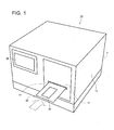
- Micro-overall-analysis system 10 shown in each of Fig. 1 - Fig. 3 includes a system main body, namely an analyzer for analysis of specimen, for which micro-pump unit 26, pump control device 28, temperature control device 38 and detecting device 44 are housed in base main body 12 and includes testing chip 50.
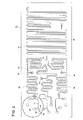
- Testing chip 50 whose outline is shown in Fig. 2 is equipped with reagent storage sections 60 (hatched portions in Fig. 5) in each of which reagent 58 is sealed in advance, and equipped with channel 46 leading to the downstream side from the reagent storage sections 60.
- the reagent 58 is one to be supplied through reagent supply hole 56, and when the reagent 58 is supplied into the testing chip 50, the reagent 58 is filled in the storage section up to the points immediately before water-repellent valves B and C.
- reagent storage sections 60 a plurality of reagent storage sections 60 merge at merging point 70, and micro flow channel 46 is provided after the merging point.
- this micro flow channel 46 At the downstream side of this micro flow channel 46, there is provided an unillustrated specimen storage section, and specimen held in the specimen storage section and a liquid which is a mixture of plural reagents 58 passing through the micro flow channel 46 are mixed are further mixed, in the structure.
- valve portions such as water-repellent valves are arranged at proper positions, to control, for example, quantification of an amount of liquid to be sent and to control mixing of respective liquids.
- pump-connecting section 64 for connecting to chip-connecting section 66 of micro-pump unit 26 shown in Fig. 3 and gas-blower-connecting section 24 for connecting to gas-blower 32 which will be described later.
- Testing chip 50 is one constructed so that gene amplification reaction by ICAN method in the chip and automatic detection thereof and simultaneous gene diagnosis for plural genes may be carried out by injecting gene specimen extracted from blood or from spat phlegm.
- This testing chip 50 is a chip whose longitudinal length and lateral length are in several centimeters, and in its structure, amplification reaction and its detection can be carried out automatically, simply by dropping a blood specimen of about 2 - 3 ⁇ L in this chip, for example, and by mounting it on specimen analyzer 2.
- the testing chip 50 is one formed with a laminated body wherein appropriate members of resin, glass, silicon or ceramic are combined, and it is preferably formed with plastic resin for which processing is easy, cost is low and incineration dumping is easy.
- polystyrene resin is excellent in moldability, and it has strong tendency to adsorb streptoavidin, whereby, a detection region can be formed easily in a micro flow channel.
- the surface of the testing chip 50 needs to be transparent, for the purpose of detecting optically fluorescent materials or product materials showing color reactions.
- the testing chip 50 of this kind is a piece of chip made by combining properly one or more members of plastic resin, glass, silicon and ceramic.
- Micro flow channel 46 of the testing chip 50 and a frame body are preferably formed from plastic resin for which processing is easy, cost is low and incineration dumping is easy.
- polystyrene resin is excellent in moldability, and it has strong tendency to adsorb streptoavidin, whereby, a detection region can be formed easily on a micro flow channel.
- the micro flow channel is formed to be about 10 ⁇ m - several hundred ⁇ m in terms of a width and a depth.
- At least a detection section, covering detection region of the micro flow channel of the surface of the testing chip 50 is a transparent member, or preferably transparent plastic.
- respective reagents 58 held in plural reagent storage sections 60 are mixed in the reagent storage section 60 at the downstream side, and mixed reagents in respective reagent storage sections 60 are further merged at the merging point 70 to be sent to micro flow channel 46 at the downstream side.
- specimen and mixed reagent are merged and mixed from Y-shaped channel, which is not illustrated, and then, reactions are started when temperature rises, and reactions are detected by the detection region provided on the channel.
- the system of the invention can be used favorably, especially for the test of genes or of nucleic acid.
- micro flow channel 46 of the testing chip 50 is made to be of the structure suitable for PCR amplification, and the basic channel structure can be substantially the same even for biological materials other than those for genetic testing.
- Bio-materials other than genes mentioned here mean various types of metabolites, hormone and protein (including an enzyme and an antigen).
- a specimen storage section in which a specimen or analite substance (for example, DNA) extracted from the specimen is injected in one chip, a specimen preprocessing section that conducts preprocessing of the specimen, a reagent storage section that holds a reagent to be used for a probe combination reaction and a detection reaction (including also a gene amplification reaction or an antigen-antibody reaction), a positive control storage section that holds a positive control, a negative control storage section that holds a negative control, a probe storage section that holds a probe (for example, a probe to hybridize to a gene to be detected that is amplified by a gene amplification reaction), a micro flow channel that is communicated with respective storage sections and a pump-connecting section that can be connected to a separate micro-pump capable of feeding liquids in the respective storage sections and the channel.
- a specimen preprocessing section that conducts preprocessing of the specimen
- a reagent storage section that holds a reagent to be used for a probe combination reaction and
- a micro-pump through pump-connecting section 64, and thereby, a specimen held in a specimen storage section (not shown) or a bio-material extracted from the specimen (for example, DNA or other bio-materials) and reagent 58 held in reagent storage section 60 are sent to merging point 70 which is located at the downstream side of the reagent storage section 60, and are further mixed to react at a reaction region of the micro flow channel 46, for example, at a region of gene amplification reaction (an antigen-antibody reaction, in the case of protein), then, a processing liquid having processed the reacted liquid and a probe held in a probe storage section are sent to a detection section located in the channel at the downstream side thereof so that the processing liquid may be combined with the probe (or may be hybridized), thus, the bio-material is detected based on this reactive product.
- a processing liquid having processed the reacted liquid and a probe held in a probe storage section are sent to a detection section located in the channel at the downstream side thereof so that the processing
- reaction and detection are conducted even for positive control held in the positive control storage section and negative control held in the negative control storage section.
- a specimen storage section (not shown) in the testing chip 50 is communicated with a specimen injecting section which holds a specimen temporarily and supplies the specimen to a mixing section.
- the specimen injecting section through which the specimen is injected into the specimen storage section from its upper side is provided with a plug that includes an elastic body such as a rubber type material, or the specimen injecting section is covered by resin such as polydimethylsiloxane (PDMS) or by a reinforced film, for preventing leakage to the outside, infection and pollution and for securing tight sealing.
- a plug that includes an elastic body such as a rubber type material
- resin such as polydimethylsiloxane (PDMS) or by a reinforced film
- the specimen in syringe is injected by a needle pierced through the plug made of rubber material, or through a needle through which a thin hole having a cap penetrates.
- another specimen injecting mechanism may also be provided.
- the specimen injected in a specimen storage section (not shown) is subjected to preprocessing through mixing of the specimen and the processing liquid, for example, before mixing with reagent 58, as occasion demands, in the specimen preprocessing section provided on the reagent storage section 60 in advance.
- Preferable specimen preprocessing includes separation, or concentration and deproteinization of an analysis object (analite).
- a specimen preprocessing section may include a separation filter, resin for adsorption and beads.
- reagent supply hole 56 of the testing chip 50 there is sealed predetermined amount of necessary reagent in advance.
- reagent 58 when analyzing an antigen existing in bio-materials, there is used reagent 58 containing an antibody corresponding to the antigen, preferably containing monoclonal antibody.
- the antibody is preferably marked with biotin and FITC.
- Reagents for genetic test may include various reagents used for gene amplification, probes used for detection and color forming reagents, and even preprocessing reagents used for specimen preprocessing, as occasion demands.
- Reagent 58 is forced out to mixing section 70 from each reagent storage section 60 when driving liquid 31 is supplied into the testing chip 50 by a micro-pump of micro-pump unit 26.
- reaction necessary for analyses such as gene amplification reaction, trapping of an analite or antigen-antibody reaction.
- the mixing may be conducted at a desired ratio at a single mixing section, or the mixing may be conducted by providing plural merging points and dividing either one or both of them which are to be mixed such that a desired mixing ratio is be obtained finally.
- reaction region of this kind is not limited in particular, and various embodiments and styles are considered.
- micro flow channel 46 where respective types of liquids are diffused and mixed is provided after a merging point (channel diverging point) where two or more kinds of liquids including reagent 58 are merged, and reactions are carried out in a liquid reservoir (not shown) formed by a space whose width is greater than that of micro flow channel 46 and which is provided after the downstream side of the aforesaid micro flow channel 46.
- a PCR amplification method which is used commonly in many aspects can be used.
- This device system may be applied to a channel for amplification of the testing chip 50 of the invention.
- DNA amplification can be carried out in a period that is much shorter than that for the conventional method wherein DNA amplification is carried out manually, because thermal cycle can be switched at high speed, and micro flow channel 46 is made to be a micro-reaction cell whose heat capacity is small.
- ICAN isothermal chimera primer initiated nucleic acid amplification developed recently as an improvement of PCR is characterized in that DNA amplification can be carried out in a short period of time under an optional certain temperature in a range of 50 - 65°C (Patent No. 3433929).
- the ICAN method is a suitable amplification technology for the testing chip 50 of the invention, because temperature control is simple.
- This method which takes one hour in the manual operations is completed in 10 - 20 minutes, preferably in 15 minutes including also analyses, in the micro-overall-analysis system of the invention.
- analite for example, a detection region for detecting an amplified gene.
- At least its detecting portion is of the transparent material for making optical measurement possible, and preferably of transparent plastic.
- protein having affinity to biotin adsorbed to the detection region on the micro flow channel 46 avidin, strepto avidin, extra-avidin (R), preferably strepto avidin
- avidin, strepto avidin, extra-avidin (R), preferably strepto avidin combines specifically with biotin marked on probe substance, or biotin marked on 5' end of primer used for gene amplification reaction.
- cDNA compounded based on specimen or DNA extracted from the specimen, or based on specimen or RNA extracted from the specimen through reverse transfer and primer biotin-modified at 5' position are sent from their storage sections to a micro flow channel located at the down stream side.
- amplification reaction liquid containing gene amplified in the micro flow channel and a denatured liquid are mixed to make the amplified gene to be a single strand, and this and probe DNA of which end is marked with fluorescence through FITC (fluorescein isothiocyanate) are hybridized.
- a liquid is sent to the detection region in the micro flow channel where protein having affinity to biotin is adsorbed, and the amplified gene is trapped in the detection region in the micro flow channel.
- Probe DNA marked with fluorescence may be hybridized after the amplified gene is trapped in the detection region.
- a reagent containing antibody specific for the analite such as an antigen, a metabolite and hormone existing in a specimen, preferably monoclonal antibody, is mixed with a specimen.
- the antibody is marked with biotin and FITC.
- a product obtained through an antigen-antibody reaction has therein biotin and FITC.
- This product is sent to a detection region, in the micro flow channel, which has adsorbed biotin-affinity protein (preferably, streptoavidin) to be fixed on the detection region through the combination of the biotin-affinity protein and the biotin.
- biotin-affinity protein preferably, streptoavidin
- a gold-colloidal liquid whose surface is modified with anti-FITC antibody that combines specifically with FITC is let to flow into the micro flow channel, and thereby, the gold colloid is adsorbed by FITC modified probe hybridized with fixed analite-antibody reactant FITC, or with a gene.
- the concentration of the gold colloid in the micro flow channel is measured optically.
- testing chip gateway 14 through which testing chip 50 is taken into the inside and display section 18 on which the results of the prescribed tests conducted in the base main body 12 are outputted.
- Testing chip 50 is placed on chip conveyance tray 22, and then, is taken into the base main body 12 through the testing chip gateway 14, to be mounted therein.
- micro-pump unit 26 that is connected to pump-connecting section 64 of the testing chip 50 and moves a specimen and a processing liquid to prescribed places and pump-control device 28 that controls liquid feeding of the micro-pump unit 26.
- temperature control device 38 that includes Pertier element 34 that is in contact with testing chip 50 and controls temperature of reagent, especially controls temperature in a channel of the reaction portion, and of heater 36.
- detection device 44 that includes LED 40 that emits light for detecting substances to be detected existing in a detection section channel of the testing chip 50 and photodiode 42 that receives transmitted light.
- micro-pump unit 26 For the system main body of the micro-overall-analysis system 10, there are integrated, on the base main body 12, micro-pump unit 26, pump control device 28 that controls the micro-pump, temperature control device 38 that controls temperatures and detecting device 44.
- testing chip 50 When mounting, on the system main body, the testing chip 50 after injecting a specimen in a specimen storage section (not shown) of the testing chip 50 in which reagent 58 is sealed in advance, mechanical connection for operating the micro-pump for liquid feeding is completed.
- testing chip 50 is mounted on the system main body, reagent storage section 60 of the testing chip 50 becomes ready to operate.
- liquid feeding for specimens and reagents, gene amplification based on mixing, reaction of combination of an analite and a probe, detection of reactants and optical measurements are carried out automatically as a series of successive processes, and necessary data are stored in a file together with necessary conditions and recorded items, thus, measurement of bio-materials is automatically carried out.
- Control systems relating to respective controls for liquid feeding, temperatures and reactions and units which are in charge of optical detection, data collection and data processing constitute the system main body, together with a micro-pump and an optical device.
- This system main body can be used commonly for respective specimen samples when the testing chip 50 is mounted thereon.
- Reaction of gene amplification and its detection are incorporated in a software installed on the system main body as a program together with control of micro-pump and temperature and with data processing of optical detection, as conditions established in advance concerning an order of liquid feeding, a volume and timing.
- Detection device 44 that detects reactions in micro flow channel 46 of the testing chip 50 causes, for example, LED to irradiate light for measurement for detection regions on an analysis channel for each test item, and detects transmitted light or reflected light with an optical detection unit such as a photodiode or a photomultiplier tube.
- an optical detection unit such as a photodiode or a photomultiplier tube.
- micro-overall-analysis system 10 Since every component in the micro-overall-analysis system 10 is downsized to be made handy to carry, the micro-overall-analysis system 10 is not restricted by time and place for its use, and it is excellent in terms of workability and operability.
- testing chip 50 is a disposable type one, because micro-pump unit 26 used for liquid feeding is incorporated on the system main body side.
- micro-pump unit 26 there are provided a plurality of micro-pumps corresponding, in terms of a number, to the number of regions to feed liquid by pushing out from the upstream side with driving liquid 31, including, for example, a specimen storage section (not shown), a plurality of reagent supply holes 56, a positive control storage section and a negative control storage section.
- a micro-pump is connected to testing chip 50 through pump-connecting section 64 of the testing chip 50 to function as a micro-pump, when the testing chip 50 is mounted on the system main body.
- micro-pump unit 26 there are provided a plurality of micro-pumps and testing chip-connecting section 66 having a channel opening for communicating with the testing chip 50.
- pump-connecting section 64 having channel openings for communicating with the micro-pumps as shown in Fig. 4, and the micro-pumps are communicated with reagent storage sections 60 of the testing chip 50, when pump-connecting section 64 of the testing chip 50 is tightly connected to testing chip-connecting section 66 of the micro-pump unit 26 on a liquid-tight basis.
- a pump-connecting section 64 of the testing chip 50 is formed by a channel opening for communicating with the micro-pump and a contact surface surrounding the channel opening
- a testing chip-connecting section 66 is formed by a channel opening for communicating with the micro-pump and a contact surface surrounding the channel opening.
- pump control device 28 controls driving of the micro-pump and driving liquid reservoir tank 30 that stores driving liquid 31.
- the aforesaid openings are connected with each other.
- Tight contact is attained by pressing testing chip 50, for example, against micro-pump unit 26.
- a piezoelectric pump As a micro-pump, it is preferable to use a piezoelectric pump.
- This piezoelectric pump is a pump which is equipped with a first channel whose channel resistance varies depending on a differential pressure, a second channel whose change rate of channel resistance for the change of differential pressure is smaller than that of the first channel, a compression chamber that is connected to the first and second channels and an actuator that changes inner pressure of the compression chamber, and is capable of feeding a liquid both in a regular direction and an opposite direction, by driving the actuator.
- Patent Document 7 Its details are described in the aforesaid Patent Document 7 and Patent Document 8.
- a silicone wafer is processed into a predetermined form by a known photolithography technology to produce a silicon substrate.
- the silicon substrate is formed into the form of the pump through etching. Then, another substrate is superimposed thereon. Thus, a piezoelectric pump is produced.
- a port is formed on the substrate of the pump unit, so that a pump is communicated with pump-connecting section 64 of the testing chip 50 through this port.
- the testing chip 50 By superimposing the vicinity of pump-connecting section 64 of the testing chip 50 vertically on the substrate on which the port is formed, the testing chip 50 can be connected to the pump unit.
- the driving liquid reservoir tank 30 is connected to a port of the pump on the opposite side to the port connected with the testing chip 50.
- plural ports provided respectively for these pumps may also be connected to the common driving liquid reservoir tank 30.
- Fig. 4 shows main detection unit 63.
- driving liquid 31 is supplied to pump unit 26 from the driving liquid reservoir tank 30 in accordance with instruction signals from pump control device 28, then, the driving liquid 31 is supplied from the micro-pump of the pump unit 26 to the testing chip 50 side through testing chip-connecting section 66 provided at the downstream side, to be supplied to a specimen storage section (not shown) or to reagent storage section 60.
- a specimen in the specimen storage section and a reagent in the reagent storage section 60 are merged and mixed through a Y-shaped channel, to be raised to a predetermined temperatures by temperature control device 38 in channel 46 so that reactions are promoted, whereby, the reactions are detected.
- An analysis system of the invention can be used favorably especially for a test of a gene or a nucleic acid.
- a micro flow channel of testing chip 50 is structured to be suitable for PCR amplification.
- the basic structure of the channel it is substantially the same even for bio-materials other than genes.
- reagents used for gene amplification are included in reagents for gene testing, and preprocessing reagent may also be included in the reagents for testing of genes if necessary.
- reaction regions are not limited in particular, and various embodiments and types are considered, not to be limited to Fig. 2.
- micro pump-connecting section 64 on the testing chip 50 side needs to be connected closely to testing chip-connecting section 66 on the specimen analyzer 2 side so that liquid channels and the like are communicated.
- Such a tight contact can be achieved by providing, for example, a pressing mechanism between micro-pump unit 26 and testing chip 50.
- the pressing mechanism there are considered various embodiments, depending on how to fit the testing chip 50 in specimen analyzer 2.
- the specimen analyzer 2 is provided with conveyance tray 22 on which the testing chip 50 is placed.
- this conveyance tray 22 is not essential naturally, and this pressing mechanism can be applied also to a specimen analyzer 2 which is not provided with conveyance tray 22, as described later.
- a wind-powered apparatus a suction unit and an electromagnet can be used as the pressing mechanism.
- the pressing mechanism can be provided on pump unit 26, detection device 44, temperature control device 38 or conveyance tray 22.
- the testing chip conveyance tray 22 shown in Fig. 1, at a predetermined position by inserting the tray 22 into the inside from entrance 14 of base main body (apparatus main body) 12 and by conveying it to primary detection unit 63 in the base main body 12, it is possible to arrange the pressing mechanism by pressing slightly upward from the lower portion or downward from the upper portion, with a proper means, for example, with a cylinder, at a point of time when the conveyance tray 22 arrives at the prescribed position on the primary detection unit 63.
- a wind-powered apparatus or a suction unit may also be used for the pressing mechanism. It is further possible to provide the pressing mechanism at a position between pump unit 26 and testing chip conveyance tray 22 on which testing chip 50 is placed.
- the temperature control device 38 includes Pertier element 34 that establishes a temperature of a reagent held in reagent storage section 60 in advance to be a predetermined temperature or lower and heater 36 that conducts heating for accelerating reaction of mixed liquid for testing and reagent in micro flow channel 46. If these Pertier element 34 and heater 36 are surely brought into close contact with testing chip 50, quality of the reagent can be maintained at good conditions for a long time, and results of detections can be obtained promptly by accelerating reactions, after the reagent and the specimen are merged together.
- the pressing mechanism is equipped with a positioning unit.
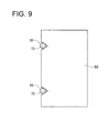
- a positioning unit may also be one for which groove 61 is formed on conveyance tray 22 and testing chip 50 is guided to a prescribed position along the groove 61, as shown in Fig. 7. Or, it may also be one for which at least two holes 67 are formed on testing chip connecting section 66 of pump unit 26, and holes 65 corresponding to the holes 67 are formed on chip 1, then, holes 67 are made to fit with holes 65 by a sensor, and pins 72 or projections are inserted downward into these holes, as shown in Fig. 8.
- the pressing mechanism interposed at the connecting section between the testing chip 50 and specimen analyzer 2 is applied also to the temperature control device 38, a contact in a proper state can be obtained between the testing chip 50 and Pertier element 34 or between the testing chip 50 and heater 36, which makes it possible to properly control a temperature at a predetermined region such as a reagent storage section or a reaction portion of the testing chip 50.
- silica gel can be housed in the inside of specimen analyzer 2 in the invention. If these desiccants are interposed, surroundings can be dried well, which prevents adsorption of dusts in the gas, and contributes to improvement of accuracy in analysis. Further, liquid leakage from the connecting section caused by adhesion of moisture at the connecting section between the testing chip 50 and pump unit 26 (micro-pump connecting section 64 and testing chip connecting section 66) can be prevented.
- the present invention is not limited to the aforesaid examples at all.
- the invention can be applied also to the occasion where the conveyance tray 22 of this kind is not provided on the specimen analyzer 2, although the conveyance tray 22 is provided on the specimen analyzer 2 in the aforesaid example.
- Fig. 10 shows another example of the invention, and in particular, it shows a structure of the inside of the specimen analyzer 2 which is not provided with a conveyance tray 22.
- Fig. 10 the same components as those in Fig. 3 are given the same symbols, and detailed description is omitted.
- micro-pump connecting section 64 is opened on the lower surface of the testing chip 50, and testing chip connecting section 66 is formed to be opened on the upper surface of pump unit 26.
- the testing chip 50 is arranged on the upper surface of the pump unit 26, with its opening section facing downward.
- elastic body 53 such as a spring or a rubber body is interposed below a placing surface of pump unit 26.
- elastic body 53 such as a spring or a rubber body is interposed below a placing surface of pump unit 26.
- hydraulic or spring-powered or motor-powered pressing mechanism 51 is provided above the testing chip 50.
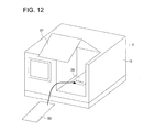
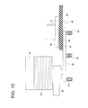
- FIG. 12 and Fig. 13 shows another example.
- conveyance tray 22 is not provided on the specimen analyzer 2, likewise as in the case of Fig. 10.
- the door 57 is opened first as illustrated, and an operator can place directly the testing chip 50 manually on the pump unit 26 arranged inside.
- plate member 55 capable of moving up and down, for example, can be prepared as a separate member, and hydraulic power, spring force or force of motor can also be applied downward through the plate member 55 representing the separate member. Force of wind may also be employed naturally. If heat insulating materials such as foam polystyrene or Bakelite, for example, is used as the plate member 55, it is possible to test accurately, because a heating temperature and a cooling temperature are stabilized. Even in the case of pressing mechanism 51 of this structure, it is possible to improve the tightness of contact between testing chip 50 and pump unit 26, likewise as in the aforesaid example.
- the pressing mechanism relating to the invention may also be conveyance tray 22, temperature control device 38 or pump unit 26, each itself.
- the pressing mechanism can be constructed by using the gravity force of the aforesaid items.
- the pressing mechanism for preventing liquid leakage from the connecting section that connects micro-pump 26 with testing chip 50 and more preferably, the specimen analyzer 2 is provided with a device to prevent, by removing driving liquid 31 in advance, that a liquid leaks out from the connecting section.
- testing chip 50 inserted into base main body 12 under the condition that the testing chip 50 is placed on the chip conveyance tray 22 is connected with micro-pump unit 26 at pump connecting section 64, at a prescribed position in the base main body 12.
- driving liquid 31 such as oil or a buffer liquid stored in driving liquid tank 30 is sent out into the testing chip 50 by a micro-pump that is driven by pump control device 28, and the driving liquid pushes out reagent and others stored in reagent storage section 60 in the testing chip 50 to merging point 70.
- gas is sent by gas-blower 32 into channel 20 provided in advance on the testing chip 50, to eliminate driving liquid 31 in advance, at the stage before testing chip connecting section 66 of the connected micro-pump unit 26 is separated from pump connecting section 64 of the testing chip 50, as shown in Fig. 3, thus, leaking out of a liquid from the connecting section is prevented.
- the gas-blower 32 of this kind is constructed so that it is connected to gas-blower connecting section 48 provided in advance on the testing chip 50, in the system main body, as shown in Fig. 3.
- liquid collection device connecting section 49 As another example, on the micro-pump unit 26 connected with pump connecting section 64 of the testing chip 50, there my be provided liquid collection device connecting section 49 as shown in Fig. 14, and liquid collection device 16 is connected to the liquid collection device connecting section 49.
- liquid collection device 16 gas is taken in channel 20 by the gas-blower 32 in the condition that micro-pump unit 26 is connected to the testing chip 50, as shown in Fig. 5, and further, driving liquid 31 is pushed up to the liquid collection device connecting section 49 of the upper micro-pump unit 26, thus, the driving liquid 31 is collected by the liquid collection device 16 connected to the liquid collection device connecting section 49.
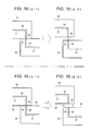
- the gas-blower 32 In the flow of collection of driving liquid 31 by the gas-blower 32, the gas-blower 32 is connected to gas-blower connecting section 48 of the testing chip 50, in the condition that testing chip connecting section 66 of micro-pump unit 26 is connected to pump connecting section 64 of the testing chip 50 as shown in Fig. 16 (a).
- driving liquid 31 in channel 59 is moved from the vicinity of the testing chip connecting section 66 and pump connecting section 64 to disappear, as shown in Fig. 16 (c).
- micro-pump unit 26 is separated from the testing chip 50 in the condition that driving liquid 31 does not exist in the neighborhood of the testing chip connecting section 66 and pump connecting section 64 as this, leakage of a liquid at the connecting section can surely be prevented.
- liquid collection device connecting section 49 is provided on the micro-pump unit 26, the gas-blower 32 is connected to gas-blower connecting section 48 of the testing chip 50, in the condition that testing chip connecting section 66 of micro-pump unit 26 is connected to pump connecting section 64 of the testing chip 50 as shown in Fig. 17 (a).
- liquid collection device 16 is connected to the liquid collection device connecting section 49 of the micro-pump unit 26.
- driving liquid 31 in the reagent storage section 60 is collected in the liquid collection device 16 through the liquid collection device connecting section 49 in the vicinity of the testing chip connecting section 66 and pump connecting section 64 as shown in Fig. 17 (c).
- a kind, an amount and a temperature of the gas that is sent out by the gas-blower 32 can be established properly so that they fit with driving liquid 31, a specimen and processing liquid stored in the testing chip 50 and with the structure of the system main body.
- the number of gas-blowers 32 can be established properly depending on the number of gas-blower-connecting sections 24 provided in the testing chip.
- the structure establishment there are given a structure wherein one gas-blower 32 is installed, and this gas-blower 32 is connected to all gas-blower-connecting sections 24 to send gas from a single gas-blower, and a structure wherein a plurality of gas-blowers 32 are installed, and respective gas-blowers 32 are connected with gas-blower-connecting sections 24 on an allotment basis to send the gas.
- the gas-blowers 32 is connected to the micro-pump unit 26 side, and driving liquid 31 in the channel near the testing chip connecting section 66 and the pump connecting section 64 is driven out when gas flows in from the micro-pump unit 26 side, and to employ a structure in which the gas-blowers 32 is connected to the micro-pump unit 26 side, and a liquid is collected by providing the liquid collection device 16 on the testing chip 50 side.
- gas-blower it is further possible to constitute to make the gas-blower to be switched freely so that it may be used on both the micro-pump unit 26 side and the testing chip 50 side, which can be varied within a range that does not depart from the spirit and scope of the invention.
- micro-pump unit 26 and the testing chip 50 are brought into close contact and driving liquid 31 is made to flow in reagent storage section 60, as shown in Fig. 18 (a-1), and then the micro-pump unit 26 are separated from the testing chip 50, as shown in Fig. 18 (a-2).
- driving liquid 31 on the surface of the pump connecting section 64 and that on the surface of the testing chip connecting section 66 are connected to each other during the initial period of the separation, and a distance between the pump connecting section 64 and the testing chip connecting section 66 is further broadened to cut the connected liquid.
- the liquid In the case of cutting the connected liquid, the liquid sometimes scatters in the system main body or on the testing chip 50.
- hydrophobic layer 52 is provided on the surface of the pump connecting section 64 and that of the testing chip connecting section 66, and in this condition, the micro-pump unit 26 and the testing chip 50 are brought into close contact each other.
- the hydrophobic layer 52 of this kind is just required to be a sealing member made of soft resin such as polyethylene, silicone and Teflon (a registered trademark), for example, and a sealing surface of the sealing member is preferably made to be a contact surface between the testing chip 50 and micro-pump unit 26.
- leakage of liquid from the connecting section is prevented by the pressing mechanism while the micro-pump unit 26 is connected to the testing chip 50, and further, at the stage before the testing chip connecting section 66 of the connected micro-pump unit 26 is separated from the pump connecting section 64 of the testing chip 50, liquid leakage from the connecting section is prevented by sending gas into channel 20 provided in the testing chip 50 in advance from gas-blower 32 (shown in Fig. 3), and thereby, by removing driving liquid 31 in advance.
- gas-blower 33 is provided more preferably, to send a wind to the contact surface in advance with the gas-blower 33 before the micro-pump is connected to the testing chip 50 to clean the contact surface by blowing off (or drying) a liquid on the contact surface.
- the foregoing is also applied even to the occasion in which the contact surface is contaminated with foreign substances.
- the gas-blower 33 is an gas-blower that is different from the aforesaid gas-blower 32, namely, the gas-blower 32 for preventing liquid leakage from the connecting section by sending gas into channel 20 provided in the testing chip 50 in advance from gas-blower 32, and thereby, removing driving liquid 31 in advance.
- An amount, a temperature and a direction of the wind that is sent out by the gas-blower 33 can be established properly so that they fit with a specimen held in the testing chip 50, a processing liquid and with the structure of the system main body.
- a place of installation and the number for the gas-blower 33 can be established properly depending on the occasion.
- the gas-blower 33 can be installed so that gas may be sent to the surface of the testing chip 50 placed on chip conveyance tray 22 on the pump connecting section side, or, the gas-blower 33 can be installed so that gas may be sent to the surface of micro-pump unit 26 on the testing chip connecting section 66 side.
- wiping device 17 that that removes a liquid (for example, moisture or a specimen) sticking to the surface of the testing chip 50 before the micro-pump is connected to the testing chip 50, is provided above testing chip gateway 14 of the base main body 12 for the testing chip 50, as a mechanism for cleaning the contact surface in advance.
- a liquid for example, moisture or a specimen
- the chip conveyance tray 22 on which the testing chip 50 is placed is moved in the direction of an arrow shown in Fig. 20 (a), because wiping device 17 is provided above the testing chip gateway 14, and an upper surface of the testing chip 50 comes in contact with the wiping device 17 as shown in Fig. 20 (b), and thereby, liquids and foreign substances sticking to the testing chip 50 are wiped off.
- scraper-shaped rubber and sponge having excellent water-absorbing property for example, and it is possible to select those which are appropriate for materials of the testing chip 50.
- testing chip 50 is cleaned, it is also possible to make the wiping device to work on testing chip connecting section 66 to wipe liquids and foreign substances off its surface before connecting the testing chip 50, by providing the wiping device 17 like that stated above on the testing chip connecting section 66 on the micro-pump unit 26.
- liquid feeding is controlled by a micro-pump and a predetermined test is conducted by using temperature control device 38 and detecting device 44, for the testing chip 50 loaded on the micro-pump unit 26.
- Results of the test are displayed on display section 18 provided on the front side of the base main body 12, and the predetermined test is completed.
- Fig. 21 is one showing another example of the wiping device of the micro-overall-analysis system of the invention.
- the wiping device 17 of this kind is provided with wiping sheet supply roll 47 on which wiping sheet 45 for wiping liquids and foreign substances off is wound, take-up reel 43 that takes up the wiping sheet 45 at prescribed timing and with elevating device 69 which is provided between the wiping sheet supply roll 47 and the take-up reel 43 and is capable of moving the wiping sheet 45 to a prescribed position.
- the testing chip 50 placed on testing chip conveyance tray 22 is constituted so that pump connecting section 64 of the testing chip 50 may be wiped by wiping device 17 in advance before the testing chip 50 is connected to micro-pump unit 26.
- the wiping sheet 45 is made to have always a constant tension by the wiping sheet supply roll 47, the elevating device 69 and the take-up reel 43.
- the wiping device 17 of this kind is constructed so that the elevating device 69 may descend toward the pump connecting section 64 when the pump connecting section 64 of the testing chip 50 comes to a point right under the elevating device 69, whereby, the wiping sheet 45 goes down to the pump connecting section 64 of the testing chip 50, and liquids and contaminations sticking to the pump connecting section 64 are wiped off accordingly.
- the wiping sheet 45 As a material of the wiping sheet 45, there is no limit in particular, but resins having water-absorbing property are preferable.
- polyvinyl alcohol poly hydroxyethyl methacrylate and polyethylene glycol are preferably used, and more preferable to be used is moisture-absorbing resin such as polyvinyl alcohol/polyacrylic acid high moisture absorbing polymer, or starch/grafted polyacrylic acid.
- sponge can also be used for wiping sheet 45.
- this sponge As a material for this sponge, there is no limit in particular, but sponge made of polyurethane, nonwoven fabric or nylon may be preferably used.
- the wiping sheet 45 made of moisture-absorbing resin or of sponge is used, liquids and foreign substances can surely be held, and it is possible to prevent surely that liquids and foreign substances leak out to the inside of the system main body.
- the wiping device 17 which has completed wiping of pump connecting section 64 retreats to a position determined in advance, so that it may not interfere with testing chip conveyance tray 22.
- take-up reel 43 makes predetermined number of turns after completion of each wiping so that pump connecting section 64 of testing chip 50 may be wiped with a fresh surface of wiping sheet 45 continually.
- wiping of the pump connecting section 64 can be carried out again after fresh wiping sheet supply roll 47 is installed.
- wiping device 17 may also be arranged so that testing chip connecting section 66 of micro-pump unit 26 may be wiped, as shown in Fig. 22.
- the wiping device 17 of this kind can remove liquids and contaminations on the pump connecting section 64 when elevating device 69 moves up and down in the same way as in the wiping device 17 shown in Fig. 21.
- the wiping device 17 can also be provided on each of both sides including the pump connecting section 64 side and the testing chip connecting section side, so that both sides of pump connecting section 64 of testing chip 50 and testing chip connecting section 66 of micro-pump unit 26 may be wiped.
Landscapes
- Chemical & Material Sciences (AREA)
- Chemical Kinetics & Catalysis (AREA)
- Dispersion Chemistry (AREA)
- Health & Medical Sciences (AREA)
- Analytical Chemistry (AREA)
- General Health & Medical Sciences (AREA)
- Physics & Mathematics (AREA)
- Biochemistry (AREA)
- Life Sciences & Earth Sciences (AREA)
- General Physics & Mathematics (AREA)
- Immunology (AREA)
- Pathology (AREA)
- Hematology (AREA)
- Clinical Laboratory Science (AREA)
- Automatic Analysis And Handling Materials Therefor (AREA)
Applications Claiming Priority (3)
| Application Number | Priority Date | Filing Date | Title |
|---|---|---|---|
| JP2005086684A JP4517909B2 (ja) | 2005-03-24 | 2005-03-24 | マイクロ総合分析システム |
| JP2005089247A JP2006267038A (ja) | 2005-03-25 | 2005-03-25 | マイクロ総合分析システム |
| JP2005094612A JP2006275735A (ja) | 2005-03-29 | 2005-03-29 | マイクロ総合分析システム |
Publications (2)
| Publication Number | Publication Date |
|---|---|
| EP1705488A2 true EP1705488A2 (fr) | 2006-09-27 |
| EP1705488A3 EP1705488A3 (fr) | 2011-11-09 |
Family
ID=36569147
Family Applications (1)
| Application Number | Title | Priority Date | Filing Date |
|---|---|---|---|
| EP06111453A Withdrawn EP1705488A3 (fr) | 2005-03-24 | 2006-03-21 | Analyseur |
Country Status (2)
| Country | Link |
|---|---|
| US (1) | US8021629B2 (fr) |
| EP (1) | EP1705488A3 (fr) |
Cited By (2)
| Publication number | Priority date | Publication date | Assignee | Title |
|---|---|---|---|---|
| DE102013111778B3 (de) * | 2013-10-25 | 2015-04-30 | Bürkert Werke GmbH | Mikrofluidische Geräteeinheit |
| WO2024073059A3 (fr) * | 2022-09-30 | 2024-05-23 | Coagulo Medical Technologies, Inc. | Appareil modulaire pour tester une cartouche microfluidique, utile pour des diagnostics médicaux décolalisés et d'autres applications |
Families Citing this family (7)
| Publication number | Priority date | Publication date | Assignee | Title |
|---|---|---|---|---|
| US8012744B2 (en) * | 2006-10-13 | 2011-09-06 | Theranos, Inc. | Reducing optical interference in a fluidic device |
| JP5426476B2 (ja) * | 2010-05-21 | 2014-02-26 | 株式会社エンプラス | 分析用具及びマイクロ分析システム |
| US9260763B2 (en) | 2012-10-22 | 2016-02-16 | Qiagen Gaithersburg, Inc. | Sample processing method using tube strips and tube strip holder |
| US9435718B2 (en) | 2012-10-22 | 2016-09-06 | Qiagen Gaithersburg, Inc. | Automated pelletized sample decanting apparatus and methods |
| US9310281B2 (en) * | 2012-10-22 | 2016-04-12 | Qiagen Gaithersburg, Inc. | Automated pelletized sample blotting apparatus and methods |
| JP7043220B2 (ja) | 2017-10-30 | 2022-03-29 | アークレイ株式会社 | 分析装置及び位置決め方法 |
| CN110261310B (zh) * | 2019-07-10 | 2024-12-31 | 深圳金迈隆电子技术有限公司 | 一种片上实验室检测装置 |
Citations (5)
| Publication number | Priority date | Publication date | Assignee | Title |
|---|---|---|---|---|
| US6368079B2 (en) * | 1998-12-23 | 2002-04-09 | Battelle Pulmonary Therapeutics, Inc. | Piezoelectric micropump |
| US6383452B1 (en) * | 1999-03-17 | 2002-05-07 | Hitachi, Ltd. | Chemical analyzer and chemical analyzing system |
| JP2005086684A (ja) | 2003-09-10 | 2005-03-31 | Minolta Co Ltd | 撮像装置 |
| JP2005094612A (ja) | 2003-09-19 | 2005-04-07 | Seiko Epson Corp | 固体撮像装置及びその駆動方法 |
| JP2005089247A (ja) | 2003-09-17 | 2005-04-07 | Jfe Refractories Corp | カーボンボンドを生成する黒鉛含有流し込み不定形耐火物 |
Family Cites Families (20)
| Publication number | Priority date | Publication date | Assignee | Title |
|---|---|---|---|---|
| JP2948069B2 (ja) * | 1993-09-20 | 1999-09-13 | 株式会社日立製作所 | 化学分析装置 |
| US6240790B1 (en) * | 1998-11-09 | 2001-06-05 | Agilent Technologies, Inc. | Device for high throughout sample processing, analysis and collection, and methods of use thereof |
| US6358387B1 (en) * | 2000-03-27 | 2002-03-19 | Caliper Technologies Corporation | Ultra high throughput microfluidic analytical systems and methods |
| JP3629405B2 (ja) | 2000-05-16 | 2005-03-16 | コニカミノルタホールディングス株式会社 | マイクロポンプ |
| US20020164824A1 (en) * | 2001-02-16 | 2002-11-07 | Jianming Xiao | Method and apparatus based on bundled capillaries for high throughput screening |
| JP2002286736A (ja) * | 2001-03-28 | 2002-10-03 | Canon Inc | プローブ担体の製造方法およびプローブ担体の製造装置 |
| US6881579B2 (en) * | 2001-07-30 | 2005-04-19 | Agilent Technologies, Inc. | Sample processing apparatus and methods |
| JP2003181255A (ja) * | 2001-12-21 | 2003-07-02 | Minolta Co Ltd | マイクロチップ、該マイクロチップを用いた検査装置及び混合方法 |
| JP2004061320A (ja) * | 2002-07-29 | 2004-02-26 | Kawamura Inst Of Chem Res | マイクロ流体デバイスの送液方法 |
| JP4057967B2 (ja) * | 2002-07-31 | 2008-03-05 | 株式会社東芝 | 塩基配列自動解析装置 |
| JP3725109B2 (ja) | 2002-09-19 | 2005-12-07 | 財団法人生産技術研究奨励会 | マイクロ流体デバイス |
| JP3735719B2 (ja) * | 2002-12-25 | 2006-01-18 | 独立行政法人産業技術総合研究所 | バルブ付きマイクロ流路チップ用ソケット |
| DE102004022423A1 (de) * | 2004-05-06 | 2005-12-15 | Siemens Ag | Mikrofluidiksystem |
| JP2006121935A (ja) | 2004-10-27 | 2006-05-18 | Konica Minolta Medical & Graphic Inc | 前処理手段および廃液貯留部を有する生体物質検査用マイクロリアクタ |
| JP2006121934A (ja) | 2004-10-27 | 2006-05-18 | Konica Minolta Medical & Graphic Inc | 生体物質検査デバイス |
| US7820109B2 (en) * | 2005-04-20 | 2010-10-26 | Konica Minolta Medical & Graphic Inc. | Testing chip and micro analysis system |
| EP1882950A4 (fr) * | 2005-05-19 | 2012-08-15 | Konica Minolta Med & Graphic | Puce de test pour analyser une substance cible dans une substance à analyser et système analytique à l'échelle microscopique |
| US7757561B2 (en) * | 2005-08-01 | 2010-07-20 | Covaris, Inc. | Methods and systems for processing samples using acoustic energy |
| US20080131327A1 (en) * | 2006-09-28 | 2008-06-05 | California Institute Of Technology | System and method for interfacing with a microfluidic chip |
| JP2008122234A (ja) * | 2006-11-13 | 2008-05-29 | Konica Minolta Medical & Graphic Inc | マイクロ総合分析チップおよびマイクロ総合分析システム |
-
2006
- 2006-03-17 US US11/378,516 patent/US8021629B2/en not_active Expired - Fee Related
- 2006-03-21 EP EP06111453A patent/EP1705488A3/fr not_active Withdrawn
Patent Citations (5)
| Publication number | Priority date | Publication date | Assignee | Title |
|---|---|---|---|---|
| US6368079B2 (en) * | 1998-12-23 | 2002-04-09 | Battelle Pulmonary Therapeutics, Inc. | Piezoelectric micropump |
| US6383452B1 (en) * | 1999-03-17 | 2002-05-07 | Hitachi, Ltd. | Chemical analyzer and chemical analyzing system |
| JP2005086684A (ja) | 2003-09-10 | 2005-03-31 | Minolta Co Ltd | 撮像装置 |
| JP2005089247A (ja) | 2003-09-17 | 2005-04-07 | Jfe Refractories Corp | カーボンボンドを生成する黒鉛含有流し込み不定形耐火物 |
| JP2005094612A (ja) | 2003-09-19 | 2005-04-07 | Seiko Epson Corp | 固体撮像装置及びその駆動方法 |
Cited By (3)
| Publication number | Priority date | Publication date | Assignee | Title |
|---|---|---|---|---|
| DE102013111778B3 (de) * | 2013-10-25 | 2015-04-30 | Bürkert Werke GmbH | Mikrofluidische Geräteeinheit |
| US9592502B2 (en) | 2013-10-25 | 2017-03-14 | Bürkert Werke GmbH | Microfluidic device unit |
| WO2024073059A3 (fr) * | 2022-09-30 | 2024-05-23 | Coagulo Medical Technologies, Inc. | Appareil modulaire pour tester une cartouche microfluidique, utile pour des diagnostics médicaux décolalisés et d'autres applications |
Also Published As
| Publication number | Publication date |
|---|---|
| US20060213291A1 (en) | 2006-09-28 |
| US8021629B2 (en) | 2011-09-20 |
| EP1705488A3 (fr) | 2011-11-09 |
Similar Documents
| Publication | Publication Date | Title |
|---|---|---|
| US7482585B2 (en) | Testing chip and micro integrated analysis system | |
| US8133456B2 (en) | Microreactor and method of liquid feeding making use of the same | |
| CN108139418B (zh) | 受试体处理芯片、受试体处理装置及受试体处理方法 | |
| US7820109B2 (en) | Testing chip and micro analysis system | |
| US20200164372A1 (en) | Analysis system for testing a sample | |
| US20180099279A1 (en) | Analysis device and method for testing a sample | |
| US8021629B2 (en) | Analyzer | |
| JP2007120399A (ja) | マイクロ流体チップおよびマイクロ総合分析システム | |
| JP2007136379A (ja) | マイクロリアクタおよびその製造方法 | |
| WO2008047533A1 (fr) | Système de détection de réaction de puce, et procédé de réaction de puce dans un trajet d'écoulement | |
| JP4687413B2 (ja) | マイクロチップにおける2種類以上の液体の混合方法およびマイクロ総合分析システム | |
| JP2006284323A (ja) | マイクロ総合分析システム | |
| JP4517909B2 (ja) | マイクロ総合分析システム | |
| US20210268502A1 (en) | Analysis device and method for testing a sample | |
| JP2007139501A (ja) | マイクロチップへの試薬の充填方法 | |
| US20210008564A1 (en) | Analysis device, cartridge, analysis system and method for testing a sample | |
| JP2006267038A (ja) | マイクロ総合分析システム | |
| JP2006266925A (ja) | マイクロ総合分析システム | |
| JP2006284451A (ja) | 検体中の標的物質を分析するためのマイクロ総合分析システム | |
| WO2022136248A1 (fr) | Système d'analyse permettant de tester un échantillon | |
| JP2006275735A (ja) | マイクロ総合分析システム |
Legal Events
| Date | Code | Title | Description |
|---|---|---|---|
| PUAI | Public reference made under article 153(3) epc to a published international application that has entered the european phase |
Free format text: ORIGINAL CODE: 0009012 |
|
| AK | Designated contracting states |
Kind code of ref document: A2 Designated state(s): AT BE BG CH CY CZ DE DK EE ES FI FR GB GR HU IE IS IT LI LT LU LV MC NL PL PT RO SE SI SK TR |
|
| AX | Request for extension of the european patent |
Extension state: AL BA HR MK YU |
|
| RAP1 | Party data changed (applicant data changed or rights of an application transferred) |
Owner name: KONICA MINOLTA MEDICAL & GRAPHIC, INC. |
|
| RIC1 | Information provided on ipc code assigned before grant |
Ipc: B01L 3/00 20060101ALI20110708BHEP Ipc: G01N 35/00 20060101AFI20110708BHEP |
|
| PUAL | Search report despatched |
Free format text: ORIGINAL CODE: 0009013 |
|
| AK | Designated contracting states |
Kind code of ref document: A3 Designated state(s): AT BE BG CH CY CZ DE DK EE ES FI FR GB GR HU IE IS IT LI LT LU LV MC NL PL PT RO SE SI SK TR |
|
| AX | Request for extension of the european patent |
Extension state: AL BA HR MK YU |
|
| RIC1 | Information provided on ipc code assigned before grant |
Ipc: B01F 13/00 20060101ALN20111006BHEP Ipc: B01F 5/06 20060101ALN20111006BHEP Ipc: B01L 3/00 20060101ALI20111006BHEP Ipc: G01N 35/00 20060101AFI20111006BHEP |
|
| 17P | Request for examination filed |
Effective date: 20120504 |
|
| AKX | Designation fees paid |
Designated state(s): DE FR GB |
|
| 17Q | First examination report despatched |
Effective date: 20130102 |
|
| STAA | Information on the status of an ep patent application or granted ep patent |
Free format text: STATUS: THE APPLICATION IS DEEMED TO BE WITHDRAWN |
|
| 18D | Application deemed to be withdrawn |
Effective date: 20130514 |