EP1705678A2 - Membrane de recouvrement pour un interrupteur à bouton poussoir - Google Patents
Membrane de recouvrement pour un interrupteur à bouton poussoir Download PDFInfo
- Publication number
- EP1705678A2 EP1705678A2 EP06003879A EP06003879A EP1705678A2 EP 1705678 A2 EP1705678 A2 EP 1705678A2 EP 06003879 A EP06003879 A EP 06003879A EP 06003879 A EP06003879 A EP 06003879A EP 1705678 A2 EP1705678 A2 EP 1705678A2
- Authority
- EP
- European Patent Office
- Prior art keywords
- metal plate
- thin metal
- cover sheet
- pushbutton switch
- switch cover
- Prior art date
- Legal status (The legal status is an assumption and is not a legal conclusion. Google has not performed a legal analysis and makes no representation as to the accuracy of the status listed.)
- Withdrawn
Links
- 239000002184 metal Substances 0.000 claims abstract description 144
- 230000003014 reinforcing effect Effects 0.000 claims abstract description 108
- 238000005452 bending Methods 0.000 claims abstract description 20
- 239000000463 material Substances 0.000 claims abstract description 15
- 239000013013 elastic material Substances 0.000 claims abstract description 12
- 229920005989 resin Polymers 0.000 claims description 13
- 239000011347 resin Substances 0.000 claims description 13
- 238000010276 construction Methods 0.000 claims description 4
- 239000004431 polycarbonate resin Substances 0.000 claims description 4
- 229920005668 polycarbonate resin Polymers 0.000 claims description 4
- 229920005990 polystyrene resin Polymers 0.000 claims description 2
- 230000009467 reduction Effects 0.000 description 21
- 230000000881 depressing effect Effects 0.000 description 18
- 230000004048 modification Effects 0.000 description 12
- 238000012986 modification Methods 0.000 description 12
- 238000005286 illumination Methods 0.000 description 9
- 239000000853 adhesive Substances 0.000 description 8
- 230000001070 adhesive effect Effects 0.000 description 8
- 210000000282 nail Anatomy 0.000 description 8
- 230000000994 depressogenic effect Effects 0.000 description 5
- 210000004905 finger nail Anatomy 0.000 description 4
- 230000015572 biosynthetic process Effects 0.000 description 3
- 238000000034 method Methods 0.000 description 3
- 238000000465 moulding Methods 0.000 description 3
- 238000007639 printing Methods 0.000 description 3
- 229920002379 silicone rubber Polymers 0.000 description 3
- 239000004945 silicone rubber Substances 0.000 description 3
- 229910001220 stainless steel Inorganic materials 0.000 description 3
- 239000010935 stainless steel Substances 0.000 description 3
- 229920002725 thermoplastic elastomer Polymers 0.000 description 3
- 230000000694 effects Effects 0.000 description 2
- 238000004519 manufacturing process Methods 0.000 description 2
- 230000008569 process Effects 0.000 description 2
- XLYOFNOQVPJJNP-UHFFFAOYSA-N water Substances O XLYOFNOQVPJJNP-UHFFFAOYSA-N 0.000 description 2
- 238000011109 contamination Methods 0.000 description 1
- 230000006866 deterioration Effects 0.000 description 1
- 230000004069 differentiation Effects 0.000 description 1
- 238000006073 displacement reaction Methods 0.000 description 1
- 230000001747 exhibiting effect Effects 0.000 description 1
- 239000011888 foil Substances 0.000 description 1
- 238000002347 injection Methods 0.000 description 1
- 239000007924 injection Substances 0.000 description 1
- 230000002452 interceptive effect Effects 0.000 description 1
- 239000007788 liquid Substances 0.000 description 1
- 230000003647 oxidation Effects 0.000 description 1
- 238000007254 oxidation reaction Methods 0.000 description 1
- 238000001259 photo etching Methods 0.000 description 1
- 229920003051 synthetic elastomer Polymers 0.000 description 1
- 239000005061 synthetic rubber Substances 0.000 description 1
- 229920001169 thermoplastic Polymers 0.000 description 1
- 239000004416 thermosoftening plastic Substances 0.000 description 1
- 239000012780 transparent material Substances 0.000 description 1
Images



Classifications
-
- H—ELECTRICITY
- H01—ELECTRIC ELEMENTS
- H01H—ELECTRIC SWITCHES; RELAYS; SELECTORS; EMERGENCY PROTECTIVE DEVICES
- H01H13/00—Switches having rectilinearly-movable operating part or parts adapted for pushing or pulling in one direction only, e.g. push-button switch
- H01H13/70—Switches having rectilinearly-movable operating part or parts adapted for pushing or pulling in one direction only, e.g. push-button switch having a plurality of operating members associated with different sets of contacts, e.g. keyboard
- H01H13/702—Switches having rectilinearly-movable operating part or parts adapted for pushing or pulling in one direction only, e.g. push-button switch having a plurality of operating members associated with different sets of contacts, e.g. keyboard with contacts carried by or formed from layers in a multilayer structure, e.g. membrane switches
- H01H13/705—Switches having rectilinearly-movable operating part or parts adapted for pushing or pulling in one direction only, e.g. push-button switch having a plurality of operating members associated with different sets of contacts, e.g. keyboard with contacts carried by or formed from layers in a multilayer structure, e.g. membrane switches characterised by construction, mounting or arrangement of operating parts, e.g. push-buttons or keys
-
- H—ELECTRICITY
- H01—ELECTRIC ELEMENTS
- H01H—ELECTRIC SWITCHES; RELAYS; SELECTORS; EMERGENCY PROTECTIVE DEVICES
- H01H2209/00—Layers
- H01H2209/068—Properties of the membrane
- H01H2209/07—Properties of the membrane metallic
-
- H—ELECTRICITY
- H01—ELECTRIC ELEMENTS
- H01H—ELECTRIC SWITCHES; RELAYS; SELECTORS; EMERGENCY PROTECTIVE DEVICES
- H01H2209/00—Layers
- H01H2209/068—Properties of the membrane
- H01H2209/074—Properties of the membrane elastomeric
-
- H—ELECTRICITY
- H01—ELECTRIC ELEMENTS
- H01H—ELECTRIC SWITCHES; RELAYS; SELECTORS; EMERGENCY PROTECTIVE DEVICES
- H01H2221/00—Actuators
- H01H2221/002—Actuators integral with membrane
- H01H2221/004—U-shaped openings surrounding keys
-
- H—ELECTRICITY
- H01—ELECTRIC ELEMENTS
- H01H—ELECTRIC SWITCHES; RELAYS; SELECTORS; EMERGENCY PROTECTIVE DEVICES
- H01H2221/00—Actuators
- H01H2221/08—Actuators composed of different parts
Definitions
- This invention relates to a pushbutton switch cover sheet for the key depressing-operation portion of an apparatus, such as a mobile phone, a personal digital assistant (PDA), a car navigation apparatus, or a car audio apparatus.
- an apparatus such as a mobile phone, a personal digital assistant (PDA), a car navigation apparatus, or a car audio apparatus.
- JP 2003-197063 A discloses a resin key top in which a large number of metal foil pieces are laminated on the surface of the resin key top to form a specular gloss layer, thereby attaining a metallic tone.
- Japanese patent application No.2004-313857 discloses a pushbutton switch cover sheet using a single thin metal plate. As shown in Figs.
- a pushbutton switch cover sheet (101) as disclosed in Japanese patent application No.2004-313857 has a structure in which a thin metal plate (102) formed of a single metal plate is firmly attached to a base sheet (103) formed of a rubber-like elastic material, and in which tongue-shaped dividing grooves (104) are formed in the thin metal plate (102) having display portions (105), allowing depression-displacement of each display portion (105).
- the pushbutton switch cover sheet (101) disclosed in Japanese patent application No.2004-313857, in which the key input operating surface is formed by the thin metal plate (102), provides a novel design.
- the thickness of the thin metal plate (102) is as small as 50 ⁇ m to 300 ⁇ m, which is to be regarded as a problem. That is, in performing key input operation, when a key is depressed with a sharp object such as a fingernail tip or with an excessive force, the surface may be damaged or dented, or the periphery of the dividing grooves (104) or of the display portions (105) may suffer deformation, such as bending.
- the present invention has been made in view of the above problem in the prior art.
- the present invention provides a pushbutton switch cover sheet (hereinafter also referred to as "cover sheet”) formed by using a thin metal plate, in which damage or deformation, such as bending or denting, of the thin metal plate is prevented, thereby making it possible to continuously maintain a satisfactory design.
- the present invention provides a pushbutton switch cover sheet including: a plurality of display portions; a plurality of depressing-operation portions for effecting key input on the display portions, respectively; a base sheet formed of a rubber-like elastic material; and a thin metal plate provided on the base sheet, characterized in that a reinforcing member formed of a polymeric material is provided for each depressing-operation portion so as to be adjacent to the thin metal plate in a direction of a thickness of the thin metal plate.
- the thin metal plate is provided on the base sheet formed of a rubber-like elastic material, the pushbutton switch cover sheet is not distorted or deflected even if the apparatus casing is equipped with no dividing rails separating the depressing-operation portions from each other. Further, since the apparatus requires no dividing rails, it is possible to impart a novel design to the apparatus. Further, since the thickness of the thin metal plate is small, it is possible to achieve a reduction in the thickness of the apparatus as a whole.
- a reinforcing member formed of a polymeric material is provided for each depressing-operation portion so as to be adjacent to the thin metal plate in the direction of the thickness thereof, so even if depressing operation is performed with a sharp object, such as a fingernail tip, or with an excessively large force, the surface of the thin metal plate does not suffer damage or deformation, such as denting or bending. Further, the surface of the thin metal plate is protected and free from contamination or oxidation, thus making it possible to provide a pushbutton switch cover sheet always exhibiting a metallic gloss.
- a pushbutton switch cover sheet in which the thin metal plate has dividing sections defining the depressing-operation portions, and in which the dividing sections are formed as U-shaped sections defining the depressing-operation portions so as to allow swinging in the direction of the thickness of the thin metal plate and as dividing holes extending through the thin metal plate.
- the thin metal plate has dividing sections defining the depressing-operation portions, and the dividing sections are formed as U-shaped sections defining the depressing-operation portions so as to allow swinging in the direction of the thickness of the thin metal plate and as dividing holes extending through the thin metal plate, when the depressing-operation portions are depressed, up-and-down swinging is possible around portions where there are no U-shaped dividing sections, so it is possible to reduce the ON-load at the time of depressing operation, thus making it possible to provide a pushbutton switch cover sheet that is superior in operability.
- the depressing-operation portions provided on the thin metal plate are defined into a U-shaped configuration by the dividing sections, it is possible to create depressing-operation portions of various configurations according to the way the U-shaped dividing sections are combined. Thus, it is possible to provide a variety in design. For example, it is possible to provide depressing-operation portions divided in opposite directions by a dividing section so as to be adjacent to each other.
- a pushbutton switch cover sheet in which the thin metal plate has dividing sections defining the depressing-operation portions and in which the dividing sections are formed as half-through dividing grooves not extending through the thin metal plate. Since the thin metal plate has dividing sections defining the depressing-operation portions, and the dividing sections are formed as half-through dividing grooves not extending through the thin metal plate, there is no danger of a finger entering a dividing section to be injured thereby. Further, since the thin metal plate retains the configuration of a single plate, deformation, such as denting or bending, does not easily occur. Further, the dividing sections can be formed by an easy working process.
- a pushbutton switch cover sheet in which a transparent reinforcing member is provided on the upper surface of the thin metal plate. Since the reinforcing member is transparent and is provided on the upper surface of the thin metal plate, there is no fear of the thin metal plate being directly damaged even if depression is effected with a sharp object, such as a fingernail tip. Further, since the thin metal plate is reinforced by the reinforcing member, there is no fear of the thin metal plate being dented or bent.
- a pushbutton switch cover sheet in which the reinforcing member is provided on the lower surface of the thin metal plate. Since the reinforcing member is provided on the lower surface of the thin metal plate, it is possible to reinforce the thin metal plate from the lower surface thereof. A thin metal plate reinforced from the lower surface thereof by a reinforcing member is not easily damaged even if the upper surface thereof is depressed with a fingernail tip or the like. Further, the thin metal plate does not easily suffer deformation, such as denting or bending.
- the thickness of the reinforcing member may range from 0.2 mm to 2.0 mm. Since the thickness of the reinforcing member may range from 0.2 mm to 2.0 mm, it is possible to meet the requirement for a reduction in thickness while reinforcing the thin metal plate.
- the thickness of the reinforcing member is the sum total of the thickness of the reinforcing member formed on the upper surface and the thickness of the reinforcing member formed on the lower surface.
- the display portion is a portion indicating a character, a symbol, a figure or the like.
- the formation of the display portions can be effected by stamping simultaneously with the formation of the dividing holes.
- the pushbutton switch cover sheet of the present invention has a novel design not to be found in conventional pushbutton switch cover members, and helps to attain a reduction in the weight, size, and thickness of the apparatus on which the pushbutton switch cover sheet is mounted.
- an illumination type cover sheet a satisfactory light guiding property is attained, and it is possible to effect uniform illumination from a desired position.
- the pushbutton switch cover sheet of the present invention is a cover sheet whose thin metal plate does not easily suffer surface damage or deformation, such as denting or bending.
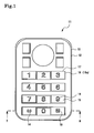
- Fig. 1 is a plan view of a pushbutton switch cover sheet (cover sheet) according to a first embodiment of the present invention
- Fig. 2 is a sectional view taken along the line II-II of Fig. 1;
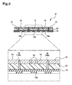
- Fig. 3 is a sectional view, corresponding to Fig. 2, of a cover sheet according to a second embodiment of the present invention
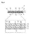
- Fig. 4 is a sectional view, corresponding to Fig. 2, of a cover sheet according to a third embodiment of the present invention.
- Fig. 5 is a plan view, corresponding to Fig. 1, of a modification of the pushbutton switch cover sheet according to the first embodiment of the present invention
- Fig. 6 is a sectional view of the pushbutton switch cover sheet taken along the line VI-VI of Fig. 5;
- Fig. 7 is a sectional view, corresponding to Fig. 2, of another modification of the pushbutton switch cover sheet according to the first embodiment of the present invention.
- Fig. 8 is a sectional view, corresponding to Fig. 2, of a modification of the pushbutton switch cover sheet according to the third embodiment of the present invention.
- Fig. 9 is a sectional view, corresponding to Fig. 2, of another modification of the pushbutton switch cover sheet according to the third embodiment of the present invention.
- Fig. 10 is a sectional view, corresponding to Fig. 2, of a modification of the pushbutton switch cover sheet according to the first embodiment of the present invention
- Fig. 11 is a sectional view, corresponding to Fig. 2, of still another modification of the pushbutton switch cover sheet according to the first embodiment of the present invention
- Fig. 12 is a plan view of a pushbutton switch cover sheet with no reinforcing member.
- Fig. 13 is a sectional view of the pushbutton switch cover sheet, taken along the line XII-XII of Fig. 12.
- the "apparatus” may be an electronic device.
- This electronic device may include a mobile phone, a PDA, a remote controller, a car navigation apparatus, a car audio apparatus, or any other device having a keypad or pushbutton switch cover sheet.
- a pushbutton switch cover sheet (11) according to a first embodiment of the present invention is formed by using an adhesive or the like to bond a thin metal plate (12) with the upper surface of a base sheet (13), the base sheet (13) being formed of a rubber-like elastic material.
- the thin metal plate (12) On the thin metal plate (12), there are provided a plurality of reinforcing members (17) formed of a transparent resin material and arranged in correspondence with the individual depressing-operation portions (15) to cover the thin metal plate (12). Side surfaces of the reinforcing members (17) are flush with the dividing sections (16), the dividing sections (16) extending through the thin metal plate (12).
- depressing the depressing-operation portions (15) may depress contacts on a printed circuit board (not shown) provided under the pushbutton switch cover sheet (11), thereby making it possible to effect key input.
- the thin metal plate (12) may be formed of a metal plate. This metal plate can be made of stainless steel or the like.
- the thickness of the thin metal plate (12) may range from 50 ⁇ m to 2000 ⁇ m. More preferably, the thickness of thin metal plate (12) may range from 50 ⁇ m to 300 ⁇ m.
- the thickness of the thin metal plate (12) is less than 50 ⁇ m, the rigidity of the thin metal plate (12) is rather low, and it is difficult to suppress distortion of the pushbutton switch cover sheet (11).
- the thickness of thin metal plate (12) exceeds 2000 ⁇ m, not only it is difficult to meet the requirement for a reduction in the thickness of the apparatus, but also a large load is required for input operation, and no tactile feel can be obtained.
- the thickness range of 50 ⁇ m to 300 ⁇ m may be preferable since, when the thickness exceeds 300 ⁇ m, it becomes somewhat difficult to perform the working process to form the dividing holes (16a) and the display portions (14) so as to cause the dividing holes 16a and the display portions (14) to extend through the thin metal plate (12). Furthermore, this thickness range from 50 ⁇ m to 2000 ⁇ m helps to meet a number of requirements, such as a reduction in apparatus thickness, the requisite rigidity of the thin metal plate (12), and depression-operability.
- the dividing holes (16a) and the display portions (14) may be formed by photo etching or the like.
- the display portions (14) need not extend through the thin metal plate (12). However, in the case of an illumination type cover sheet (11), through which illumination is effected through the display portions (14), the display portions (14) are formed as through-holes constituting light paths.
- the reinforcing members (17) provided on the thin metal plate (12) their thickness preferably ranges from 0.2 mm to 2.0 mm so that the reinforcing members (17) may prevent damage and deformation of the thin metal plate (12), and meet the requirement for a reduction in the thickness of the apparatus.
- the type of polymeric material forming the reinforcing members (17) may be, for example, a hard resin, a thermoplastic elastomer, or synthetic rubber.
- the thickness of the reinforcing members (17) is as small as 0.2 mm to 2.0 mm, it is desirable for the material of the reinforcing members (17) to be one having a bending modulus of not less than 70 MPa and a Shore D hardness of not less than 40 so that no deformation, such as bending or denting, may not occur upon depressing operation. It should be noted, however, when, as in this embodiment, the reinforcing members (17) are provided on the upper surface side of the thin metal plate (12), it is desirable to use a highly transparent and hard polymeric material, such as polymethyl metacrylate resin, polycarbonate resin, or polystyrene resin so as not to impair the design of the thin metal plate (12).
- a highly transparent and hard polymeric material such as polymethyl metacrylate resin, polycarbonate resin, or polystyrene resin
- the reinforcing members (17) may be formed of thin and rectangular parallelepiped hard resin members, may be formed as the reinforcing members (17) obtained by stamping the portions corresponding to the dividing sections (16) from a film-shaped resin material, or may be formed as film-like reinforcing members (17) obtained by applying a liquid resin to the portions corresponding to the depressing-operation portions (15).
- the base sheet (13) may be formed of a rubber-like elastic material.
- This rubber-like elastic material for the base sheet (13) may be silicone rubber or thermoplastic elastomer. Since the base sheet (13) formed of a rubber-like elastic material is provided on the lower surface of the thin metal plate (12), the thin metal plate (12) is not directly pressed against the printed circuit board but the base sheet (13) is brought into contact with the contacts on the printed circuit board. Thus, the printed circuit board can be made relatively free from damage. Further, since the base sheet (13) covers the lower surface of the thin metal plate (12), it is possible to prevent intrusion of water through the dividing holes (16a) and the display portions (14).
- the pushbutton switch cover sheet (11) may be formed of a transparent material when the pushbutton switch cover sheet (11) is to be formed as an illumination type cover sheet (11).
- the base sheet (13) prefferably has, at positions on the lower surface thereof below the depressing-operation portions (15), pushers (13a) for depressing the contacts.
- the pushers (13a) can reliably lead the depressing operation received by the depressing-operation portions (15) to conduction of the contacts, thereby making it possible to avoid a situation in which no input is effected although the depressing-operation portions (15) have been depressed.
- the thin metal plate (12) is provided in a mold, and a thermoplastic transparent hard resin constituting the reinforcing members (17) and a thermoplastic elastomer constituting the base sheet (13) are injected into the mold for integral molding.
- the reinforcing members (17) and the base sheet (13) may be formed separately, and then bonded to the thin metal plate (12) by adhesive.
- the reinforcing members (17) and the thin metal plate (12) may be fixed to each other through integral molding in which the material of the reinforcing members (17) is injected, and the thin metal plate (12) and the base sheet (13) are fixed to each other by adhesive.
- each of the reinforcing members (17) is separately formed for each depressing-operation portion (15), so no great load is required for depressing operation.
- the reinforcing members (17) are provided on the upper surfaces of the depressing-operation portions (15), there is no fear of the thin metal plate (12) suffering damage or deformation, such as bending or denting, even if depression is effected with a sharp object at the time of depressing operation.
- a pushbutton switch cover sheet (21) according to a second embodiment of the present invention differs from the pushbutton switch cover sheet (11) according to the first embodiment of the present invention in that reinforcing members (27) are provided on the lower surface of the thin metal plate (12). That is, as shown in Fig. 3, the reinforcing members (27) are provided between the thin metal plate (12) and the base sheet (13) formed of a rubber-like elastic material. Also in the production of the pushbutton switch cover sheet (21), as in the case of the pushbutton switch cover sheet (11) according to the first embodiment of the present invention, it is possible to firmly attach the thin metal plate (12), the reinforcing members (27), and the base sheet (13) to each other.
- the thin metal plate (12), the reinforcing members (27), and the base sheet (13) may be firmly attached to each other by injection integral molding.
- the thin metal plate (12), the reinforcing members (27), and the base sheet (13) may be firmly attached to each other by an adhesive.
- Other methods and processes used to firmly attach the thin metal plate (12), the reinforcing members (27), and the base sheet (13) to each other is also within the scope of the invention.
- the reinforcing members (27) reinforce the lower surface of the thin metal plate (12).
- the reinforcing members (27) do not directly protect the upper surface of the thin metal plate (12) on which input operation is conducted.
- the thin metal plate (12) is reinforced from the lower surface and increases in rigidity, it is possible to make the surface of the thin metal plate (12) relatively free from damage or deformation, such as bending or denting.
- the upper and lower reinforcing members (37a and 37b) may range from 0.1 mm to 1.0 mm. This range from 0.1 mm to 1.0 mm may permit the upper and lower reinforcing members 37a and 37b to meet the requirement for a reduction in apparatus thickness.
- the reinforcing members (37a) provided on the upper surface of the thin metal plate (12) may be formed of a transparent resin material.
- the display portions 14 may be visually recognized when the reinforcing members (37a) provided on the upper surface of the thin metal plate (12) is formed of a transparent resin material.. In this way, the reinforcing members (37a and 37b) may be provided on the upper and lower surfaces of the thin metal plate (12).
- Providing the reinforcing members (37a and 37b) on the upper and lower surfaces of the thin metal plate (12) may reinforce the thin metal plate (12). Providing the reinforcing members (37a and 37b) on the upper and lower surfaces of the thin metal plate (12) may also prevent the thin metal plate 12 from suffering damage or undergoing deformation, such as bending and denting.
- the reinforcing members (17, 27, 37a, and 37b) may be provided mainly for the purpose of preventing deformation of the thin metal plate (12), as shown in Figs. 5 and 6.
- the reinforcing members (47) associated with the pushbutton switch cover sheet (41) may be somewhat smaller than the depressing-operation portions (15) defined by the dividing sections (16).
- the reinforcing members (47) are provided on the upper surface of the thin metal plate (12), as shown in Fig. 6, the reinforcing members (47) are spaced apart from each other to a degree that an object does not directly come into contact with the thin metal plate (12).
- a pushbutton switch (51) shown in Fig. 7 may include a reinforcing member (57), the upper surfaces of the reinforcing member (57) being formed in a dome-like configuration.
- a reinforcing member (57) in which their upper surfaces are formed in a dome-like configuration it is possible to provide a pushbutton switch cover sheet (51) which is superior in operability.
- the reinforcing members (37a or 37b) provided on the upper or lower surface of the thin metal plate (12) as upwardly convex reinforcing members (67a) as shown in Fig. 8, or downwardly convex reinforcing members (77b) as shown in Fig. 9.
- the upwardly convex reinforcing members (67a) are advantageous in that the individual depressing-operation portions (15) can be easily recognized. In the case of the downwardly convex reinforcing members (77b), the depressing force is easily concentrated, and the ON-load can be reduced.
- the dividing sections (16) defining the depressing-operation portions (15) provided on the thin metal plate (12) may be formed as dividing grooves (16b) recessed on the upper side of the thin metal plate (12), or as dividing lines drawn in printing ink on the upper surface of the thin metal plate (12).
- the through-holes (16a) may lessen the input load when performing input operation.
- An example of the half-through dividing sections (16) as grooves (16b) is shown in Fig. 10.
- a base sheet (83) in the case of an illumination type cover sheet (71), it is desirable to form a base sheet (83) in a double-layer construction composed of a light-tight upper layer (83a) and a light-transmitting lower layer (83b).
- the light-tight upper layer (83a) may be formed of a film-shaped resin.
- the light-tight upper layer (83a) being formed of a rubber-like elastic material is also within the scope of the invention.
- the light-tight upper layer (83a) has through-holes (83c) corresponding to the display portions (14).
- the light-transmitting lower layer (83b) may be formed of a rubber-like elastic material, and has no such through-holes (83c) as formed in the upper layer (83a). Due to the use of the base sheet (83), constructed as described above, a pushbutton switch cover sheet (81) can prevent light leakage through the dividing holes (16a), making it possible to solely illuminate the display portions (14). Further, it is also possible to prevent intrusion of water from the display portions (14).
- the display portions (14) are provided on the thin metal plate (12), it is not always necessary to provide the display portions (14) on the thin metal plate (12). For example, it is also possible to form display portions (14) by performing printing on the reinforcing members (17) provided on the upper surface of the thin metal plate (12).
- pushbutton switch cover sheets (11, 21, 41, 51, 61, 71, and 81) of the above-described embodiments are for use in any electronic device, by, for example, changing the positional relationship of the depressing-operation portions (15) with respect to the pushbutton switch cover sheets (11, 21, 41, 51, 61, 71, and 81).
- Example 1 A pushbutton switch cover sheet (11) of the same construction as that according to the first embodiment of the present invention was manufactured.
- U-shaped dividing holes (16a) were formed in a thin metal plate (12) of a predetermined thickness formed of stainless steel, with the area of each of the tongue-shaped depressing-operation portions (15) surrounded by the dividing holes (16a) being 0.5 cm 2 .
- reinforcing members (17) of polycarbonate resin with a thickness of 0.2 mm were firmly attached by adhesive to the upper surface of the thin metal plate (12) so as to extend along and to be flush with the depressing-operation portions (15). The adhesive was caused to spread over the entire lower surfaces of the reinforcing members (17).
- a base sheet (13) which was formed of silicone rubber and whose thickness directly below the thin metal plate (12) was 0.2 mm.
- the thin metal plate (12) and the base sheet (13) were firmly attached to each other at positions spaced apart from the depressing-operation portions (15).
- Table 1 shows the results of comparison in terms of the influence on the ON-load (the load when the contact is turned on through depression of the depressing-operation portion (15)), the reinforcing effect, and the ability to meet the requirement for a reduction in apparatus thickness depending upon the difference in the thickness of the reinforcing members (17) in the pushbutton switch cover sheet (11) thus produced.
- Table 1 Relationship between the thickness of the reinforcing members and the ON-load, the reinforcing effect, and the ability to meet the requirement for a reduction in apparatus thickness Specimen No. S1 S2 S3 R1 R2 R3 Thickness of the reinforcing members (mm) 0.2 1.0 2.0 None 0.1 2.5 ON-load (N) 2.67 2.71 3.02 2.67 2.67 3.45 Reinforcing effect (*1) ⁇ ⁇ ⁇ ⁇ ⁇ ⁇
- Ability to meet the requirement for a reduction in apparatus thickness (*2) ⁇ ⁇ ⁇ ⁇ ⁇ *1) ⁇ The thin metal plate undergoes no deformation, such as bending or denting, even if depression is effected hard with a nail.
- ⁇ The thin metal plate undergoes deformation, such as bending or denting, if depression is effected hard with a nail. *2)
- ⁇ It is possible to meet the requirement for a reduction in apparatus thickness.
- ⁇ The pushbutton switch cover sheet is too thick to allow a reduction in apparatus thickness.
- specimens S1 through S3 in which the thickness of the reinforcing members (17) is 0.2 mm to 2.0 mm, no deformation, such as bending or denting, occurred even when depressing operation was effected with a nail, and it was possible to obtain a satisfactory tactile feel at the time of depressing operation.
- Example 2 A pushbutton switch cover sheet (21) of the same construction as that according to the second embodiment of the present invention was produced.
- U-shaped dividing holes (16a) were formed in a thin metal plate (12) of a predetermined thickness formed of stainless steel, with the area of each of the tongue-shaped depressing-operation portions (51) surrounded by the dividing holes (16a) being 0.5 cm 2 .
- reinforcing members (27) of polycarbonate resin with a thickness of 0.2 mm were firmly attached by adhesive to the lower surface of the thin metal plate (12) so as to extend along and to be flush with the depressing-operation portions (15). The adhesive was caused to spread over the entire surfaces of the reinforcing members (27) bonded with the thin metal plate (12).
- a base sheet (13) which was formed of silicone rubber and whose thickness directly below the depressing-operation portions (15) was 0.2 mm.
- the reinforcing member (27) and the base sheet (13) were firmly attached to each other at positions spaced apart from the depressing-operation portions (15) which does not measure the ON-load.
- Table 2 shows the results of comparison in terms of the influence on the ON-load, the reinforcing effect, and the ability to meet the requirement for a reduction in apparatus thickness depending upon the difference in the thickness of the reinforcing members (27) in the pushbutton switch cover sheet (21) thus produced.
- Table 2 Relationship between the thickness of the reinforcing members and the ON-load, the reinforcing effect, and the ability to meet the requirement for a reduction in apparatus thickness Specimen No. S4 S5 S6 R4 R5 Thickness of the reinforcing members (mm) 0,2 1.0 2.0 0.1 2.5 ON-load (N) 2.67 2.23 2.32 2.67 2.56 Reinforcing effect (*1) ⁇ ⁇ ⁇ ⁇ ⁇
- Ability to meet the requirement for a reduction in apparatus thickness (*2) ⁇ ⁇ ⁇ ⁇ *1) ⁇ The thin metal plate undergoes no deformation, such as bending or denting, even if depression is effected hard with a nail.
- ⁇ The thin metal plate undergoes deformation, such as bending or denting, if depression is effected hard with a nail. *2)
- ⁇ It is possible to meet the requirement for a reduction in apparatus thickness.
- ⁇ The pushbutton switch cover sheet is too thick to allow a reduction in apparatus thickness.
- Table 2 shows the differences in the ON-load, the reinforcing effect, and the ability to meet the requirement for a reduction in apparatus thickness depending upon the thickness of the reinforcing members in the second embodiment of the present invention.
- Table 2 shows the differences in the ON-load, the reinforcing effect, and the ability to meet the requirement for a reduction in apparatus thickness depending upon the thickness of the reinforcing members in the second embodiment of the present invention.
- Table 2 shows the differences in the ON-load, the reinforcing effect, and the ability to meet the requirement for a reduction in apparatus thickness depending upon the thickness of the reinforcing members in the second embodiment of the present invention.
- Table 2 shows the differences in the ON-load, the reinforcing effect, and the ability to meet the requirement for a reduction in apparatus thickness depending upon the thickness of the reinforcing members in the second embodiment of the present invention.
Landscapes
- Push-Button Switches (AREA)
Applications Claiming Priority (1)
| Application Number | Priority Date | Filing Date | Title |
|---|---|---|---|
| JP2005061370A JP4473752B2 (ja) | 2005-03-04 | 2005-03-04 | 押釦スイッチ用カバーシート |
Publications (2)
| Publication Number | Publication Date |
|---|---|
| EP1705678A2 true EP1705678A2 (fr) | 2006-09-27 |
| EP1705678A3 EP1705678A3 (fr) | 2007-10-17 |
Family
ID=36117646
Family Applications (1)
| Application Number | Title | Priority Date | Filing Date |
|---|---|---|---|
| EP06003879A Withdrawn EP1705678A3 (fr) | 2005-03-04 | 2006-02-25 | Membrane de recouvrement pour un interrupteur à bouton poussoir |
Country Status (4)
| Country | Link |
|---|---|
| US (3) | US20060197674A1 (fr) |
| EP (1) | EP1705678A3 (fr) |
| JP (1) | JP4473752B2 (fr) |
| CN (1) | CN1835156B (fr) |
Families Citing this family (31)
| Publication number | Priority date | Publication date | Assignee | Title |
|---|---|---|---|---|
| KR101243669B1 (ko) * | 2006-10-18 | 2013-03-25 | 엘지전자 주식회사 | 휴대 단말기 |
| JP4955442B2 (ja) * | 2007-03-30 | 2012-06-20 | ポリマテック株式会社 | 加飾シート、加飾成形体及び加飾キーシート並びに加飾シートの製造方法 |
| JP2009016315A (ja) * | 2007-07-09 | 2009-01-22 | Polymatech Co Ltd | キーシート |
| WO2009011298A1 (fr) * | 2007-07-13 | 2009-01-22 | Polymatech Co., Ltd. | Clavier souple |
| JP2009070665A (ja) * | 2007-09-12 | 2009-04-02 | Polymatech Co Ltd | キーシート |
| JP2009110778A (ja) | 2007-10-29 | 2009-05-21 | Sunarrow Ltd | キーシート |
| CN101436476B (zh) * | 2007-11-12 | 2012-02-22 | 毅嘉科技股份有限公司 | 具有波纹光泽的金属按键面板制作方法 |
| US8367235B2 (en) | 2008-01-18 | 2013-02-05 | Mophie, Inc. | Battery pack, holster, and extendible processing and interface platform for mobile devices |
| US8325955B2 (en) * | 2008-03-17 | 2012-12-04 | Auden Techno Corp. | Method for improving compatibility of hearing aid with antenna |
| US7982676B2 (en) * | 2008-10-29 | 2011-07-19 | Auden Techno Corp. | Antenna structure for a mobile phone |
| US7782610B2 (en) | 2008-11-17 | 2010-08-24 | Incase Designs Corp. | Portable electronic device case with battery |
| JP5330220B2 (ja) * | 2009-12-28 | 2013-10-30 | 信越ポリマー株式会社 | キートップ構造、電子機器およびキートップ構造の製造方法 |
| WO2011146778A1 (fr) | 2010-05-19 | 2011-11-24 | Mophie, Inc. | Accessoire de portefeuille électronique pour dispositif mobile |
| JPWO2012053187A1 (ja) * | 2010-10-22 | 2014-02-24 | パナソニック株式会社 | キーシート及びこれを用いた可動接点体 |
| EP2717734A4 (fr) | 2011-06-10 | 2015-03-04 | Mophie Inc | Accessoire de communication sans fil pour dispositif mobile |
| US9755444B2 (en) * | 2013-02-25 | 2017-09-05 | Mophie, Inc. | Protective case with switch cover |
| EP2974044A4 (fr) | 2013-03-15 | 2016-11-09 | Mophie Inc | Boîtier protecteur pour un dispositif mobile |
| CN103258665B (zh) * | 2013-05-21 | 2015-07-29 | 苏州华之杰电讯有限公司 | 一种触发调速开关 |
| WO2015081125A1 (fr) | 2013-11-27 | 2015-06-04 | Mophie, Inc. | Bloc-batterie doté d'une mémoire supplémentaire |
| JP2015149150A (ja) * | 2014-02-05 | 2015-08-20 | アルプス電気株式会社 | 揺動型スイッチ |
| CN104125734B (zh) * | 2014-07-22 | 2017-04-12 | 珠海格力电器股份有限公司 | 遥控器 |
| US9997933B2 (en) | 2014-09-03 | 2018-06-12 | Mophie, Inc. | Systems and methods for battery charging and management |
| USD797091S1 (en) | 2014-11-25 | 2017-09-12 | Mophie, Inc. | Case for a mobile electronic device |
| USD797092S1 (en) | 2014-11-25 | 2017-09-12 | Mophie, Inc. | Case for a mobile electronic device |
| USD797093S1 (en) | 2014-12-03 | 2017-09-12 | Mophie, Inc. | Case for a mobile electronic device |
| US9356267B1 (en) | 2014-12-17 | 2016-05-31 | Mophie, Inc. | Protective battery case to partially enclose a mobile electronic device |
| USD766819S1 (en) | 2015-04-06 | 2016-09-20 | Mophie, Inc. | Protective battery case |
| USD861653S1 (en) | 2015-05-27 | 2019-10-01 | Mophie Inc. | Protective battery case for mobile communications device |
| USD950538S1 (en) * | 2016-03-03 | 2022-05-03 | Mophie Inc. | Case for a mobile electronic device |
| CN107180722B (zh) * | 2017-06-29 | 2019-05-03 | 苏州达方电子有限公司 | 发光键盘 |
| US10516431B2 (en) | 2017-11-21 | 2019-12-24 | Mophie Inc. | Mobile device case for receiving wireless signals |
Citations (2)
| Publication number | Priority date | Publication date | Assignee | Title |
|---|---|---|---|---|
| JP2003197063A (ja) | 2001-12-27 | 2003-07-11 | Polymatech Co Ltd | 樹脂キートップおよびその製造方法並びに樹脂キートップ付きキーシート。 |
| JP2004313857A (ja) | 2003-04-14 | 2004-11-11 | Shokudai Hanbai Kk | 凝集沈降剤 |
Family Cites Families (9)
| Publication number | Priority date | Publication date | Assignee | Title |
|---|---|---|---|---|
| JPS5843147Y2 (ja) * | 1978-12-28 | 1983-09-29 | シャープ株式会社 | キ−入力装置 |
| JPS59103163A (ja) * | 1982-12-03 | 1984-06-14 | Casio Comput Co Ltd | シ−ト状小型電子機器 |
| JPS62115616A (ja) * | 1985-11-14 | 1987-05-27 | 松下電器産業株式会社 | キ−ボ−ド |
| US4771139A (en) * | 1986-06-27 | 1988-09-13 | Desmet Gregory L | Keyboard with metal cover and improved switches |
| JP4010355B2 (ja) * | 2001-07-16 | 2007-11-21 | ポリマテック株式会社 | 押釦スイッチ用キートップ及びその製造方法 |
| US6913517B2 (en) * | 2002-05-23 | 2005-07-05 | Cabot Microelectronics Corporation | Microporous polishing pads |
| JP4165646B2 (ja) * | 2003-12-25 | 2008-10-15 | ポリマテック株式会社 | キーシート |
| US7070349B2 (en) * | 2004-06-18 | 2006-07-04 | Motorola, Inc. | Thin keyboard and components for electronics devices and methods |
| TWI269332B (en) * | 2005-06-29 | 2006-12-21 | Speed Tech Corp | Keypad and manufacturing method thereof |
-
2005
- 2005-03-04 JP JP2005061370A patent/JP4473752B2/ja not_active Expired - Lifetime
-
2006
- 2006-02-25 EP EP06003879A patent/EP1705678A3/fr not_active Withdrawn
- 2006-03-01 US US11/363,930 patent/US20060197674A1/en not_active Abandoned
- 2006-03-02 CN CN2006100547305A patent/CN1835156B/zh not_active Expired - Fee Related
-
2008
- 2008-03-27 US US12/078,108 patent/US20080185274A1/en not_active Abandoned
- 2008-03-27 US US12/078,104 patent/US7829810B2/en not_active Expired - Fee Related
Patent Citations (2)
| Publication number | Priority date | Publication date | Assignee | Title |
|---|---|---|---|---|
| JP2003197063A (ja) | 2001-12-27 | 2003-07-11 | Polymatech Co Ltd | 樹脂キートップおよびその製造方法並びに樹脂キートップ付きキーシート。 |
| JP2004313857A (ja) | 2003-04-14 | 2004-11-11 | Shokudai Hanbai Kk | 凝集沈降剤 |
Also Published As
| Publication number | Publication date |
|---|---|
| JP2006244924A (ja) | 2006-09-14 |
| CN1835156B (zh) | 2010-09-08 |
| US7829810B2 (en) | 2010-11-09 |
| JP4473752B2 (ja) | 2010-06-02 |
| EP1705678A3 (fr) | 2007-10-17 |
| CN1835156A (zh) | 2006-09-20 |
| US20080185273A1 (en) | 2008-08-07 |
| US20080185274A1 (en) | 2008-08-07 |
| US20060197674A1 (en) | 2006-09-07 |
Similar Documents
| Publication | Publication Date | Title |
|---|---|---|
| US7829810B2 (en) | Pushbutton switch cover sheet | |
| US7538286B2 (en) | Key sheet and pushbutton switch | |
| US7034235B2 (en) | Key sheet | |
| TWI457960B (zh) | 窄的按鍵開關 | |
| US7465889B2 (en) | Pushbutton switch cover sheet and method of manufacturing the same | |
| JP4435507B2 (ja) | キーシート | |
| EP2709134A1 (fr) | Commutateur à deux étages | |
| JP2009187854A (ja) | キーシート | |
| EP2015329B1 (fr) | Feuille à touches | |
| US7358454B2 (en) | Key sheet | |
| KR20080056647A (ko) | 가동 접점체와 이를 이용한 스위치 | |
| US20080197005A1 (en) | Ultra-thin keypad | |
| US7705256B2 (en) | Thin key sheet | |
| JP2004227867A (ja) | 押釦スイッチ用部材及びその製造方法 | |
| JP4347679B2 (ja) | キーシート | |
| JP2000188036A (ja) | スイッチ機構 | |
| KR101347426B1 (ko) | 키탑 구조, 전자기기 및 키탑 구조의 제조 방법 | |
| KR100538112B1 (ko) | 플라스틱 시트를 이용한 버튼 플레이트 및 개인휴대단말기 | |
| JP2008077850A (ja) | 押圧スイッチ | |
| JP4362361B2 (ja) | キーシート | |
| JP2003138124A (ja) | プラスチックシート状材及び積層成形体並びにフィルムキー | |
| JP2010027542A (ja) | シートスイッチモジュール | |
| CN102224555A (zh) | 键盘板的制造方法及键盘板 | |
| TWM449301U (zh) | 懸臂式鍵盤裝置 |
Legal Events
| Date | Code | Title | Description |
|---|---|---|---|
| PUAI | Public reference made under article 153(3) epc to a published international application that has entered the european phase |
Free format text: ORIGINAL CODE: 0009012 |
|
| AK | Designated contracting states |
Kind code of ref document: A2 Designated state(s): AT BE BG CH CY CZ DE DK EE ES FI FR GB GR HU IE IS IT LI LT LU LV MC NL PL PT RO SE SI SK TR |
|
| AX | Request for extension of the european patent |
Extension state: AL BA HR MK YU |
|
| PUAL | Search report despatched |
Free format text: ORIGINAL CODE: 0009013 |
|
| AK | Designated contracting states |
Kind code of ref document: A3 Designated state(s): AT BE BG CH CY CZ DE DK EE ES FI FR GB GR HU IE IS IT LI LT LU LV MC NL PL PT RO SE SI SK TR |
|
| AX | Request for extension of the european patent |
Extension state: AL BA HR MK YU |
|
| 17P | Request for examination filed |
Effective date: 20080409 |
|
| 17Q | First examination report despatched |
Effective date: 20080528 |
|
| AKX | Designation fees paid |
Designated state(s): DE FI GB SE |
|
| STAA | Information on the status of an ep patent application or granted ep patent |
Free format text: STATUS: THE APPLICATION IS DEEMED TO BE WITHDRAWN |
|
| 18D | Application deemed to be withdrawn |
Effective date: 20120901 |