EP1705687A1 - Procédé de détection d'arc - Google Patents
Procédé de détection d'arc Download PDFInfo
- Publication number
- EP1705687A1 EP1705687A1 EP05006680A EP05006680A EP1705687A1 EP 1705687 A1 EP1705687 A1 EP 1705687A1 EP 05006680 A EP05006680 A EP 05006680A EP 05006680 A EP05006680 A EP 05006680A EP 1705687 A1 EP1705687 A1 EP 1705687A1
- Authority
- EP
- European Patent Office
- Prior art keywords
- signal
- determined
- output signal
- duration
- wave
- Prior art date
- Legal status (The legal status is an assumption and is not a legal conclusion. Google has not performed a legal analysis and makes no representation as to the accuracy of the status listed.)
- Granted
Links
Images

Classifications
-
- H—ELECTRICITY
- H01—ELECTRIC ELEMENTS
- H01J—ELECTRIC DISCHARGE TUBES OR DISCHARGE LAMPS
- H01J37/00—Discharge tubes with provision for introducing objects or material to be exposed to the discharge, e.g. for the purpose of examination or processing thereof
- H01J37/32—Gas-filled discharge tubes
- H01J37/32431—Constructional details of the reactor
- H01J37/32623—Mechanical discharge control means
-
- H—ELECTRICITY
- H01—ELECTRIC ELEMENTS
- H01J—ELECTRIC DISCHARGE TUBES OR DISCHARGE LAMPS
- H01J2237/00—Discharge tubes exposing object to beam, e.g. for analysis treatment, etching, imaging
- H01J2237/02—Details
- H01J2237/0203—Protection arrangements
- H01J2237/0206—Extinguishing, preventing or controlling unwanted discharges
Definitions
- the invention relates to a method for arc detection in a plasma process, which is fed by a particular free-swinging alternator with an output signal of the alternator for power supply, one with the timing of the output signal or an output signal related to the internal signal of the alternator in relation standing size is measured or determined
- the coating of substrates e.g. Glass surfaces by sputtering / sputtering in plasma processes, both reactive and conventional, are e.g. known from the architectural glass coating.
- a plasma is generated with a current or voltage source, which removes material from a target, which is deposited on the substrate, e.g. the glass pane, deposits.
- the atoms can still combine with gas atoms or molecules in a reactive process, depending on the desired coating.
- MF generators are commonly used, which usually work at a frequency of 10 - 500kHz. These are available as so-called free-swinging MF generators or as MF generators with fixed frequency.
- the freely oscillating MF generators are usually constructed as follows: From a single or multi-phase voltage of the supply network is a regulated or unregulated DC voltage, the DC link voltage generated. The DC link voltage is converted with an inverter circuit (eg bridge circuit) to a medium frequency (MF) AC voltage (10-500kHz). The MF output power signal is switched to a resonant circuit, which is excited to vibrate. In this case, the inverter is operated so that the resonant circuit is operated in the vicinity of the resonance frequency.
- MF medium frequency
- the resonant circuit may be a series resonant circuit or a parallel resonant circuit.
- a series resonant circuit is excited with an output power signal having a voltage source characteristic
- the parallel circuit is excited with an output power signal having a current source characteristic.
- inductors with a sufficiently large inductance are connected in series with the inverter.
- the MF power is coupled to the coil of the resonant circuit and connected to two electrodes in a coating chamber of a coating system, so that in the coating chamber, a plasma can be generated.
- the decoupling can be done via an output transformer, which ensures the galvanic isolation from the mains.
- the electrodes operate alternately as anode and cathode in an MF excitation system.
- the resonant frequency of the resonant circuit is dependent on the impedance of the plasma.
- the controller for the inverter In order for the inverter to always operate near the resonant frequency, the controller for the inverter must monitor the period or duration of a half cycle of the MF output power signal. It takes the duration of the period or half-wave as a measure of the duration of the next switching of the inverter. If the duration of the period or half-wave changes, this is an indication that the plasma impedance has changed.
- the object of the present invention is to provide a method and a device for an even faster arc detection.
- This object is achieved by a method in the aforementioned type in that, taking into account the time course, a reference variable is determined, the reference variable is compared with a threshold value and an arc is detected for a given comparison result. While it is known in the art to monitor an output signal and to deduce from the monitoring of plasma impedance changes and, if appropriate, to adapt the plasma process, it is possible with the method according to the invention to quickly detect the occurrence of arcs in the plasma process and to react to them if necessary. As an output signal related to the internal signal, for example, an output signal of an inverter of the alternator is in question, which is applied to an output resonant circuit of the alternator.
- the magnitude, the period duration or the frequency spectrum of the output signal or of the internal signal related to the output signal can be considered as the quantity related to the time profile.
- This method enables extremely fast arc detection.
- an arc can within half a period, i. be detected within 40 ⁇ s.
- the power supply to the plasma process is interrupted, in particular interrupted for a predefinable period of time.
- the residual energy in the output resonant circuit can swing out and arcs are not additionally supplied with energy. This leads to a rapid erasure of arcs and thus to minor damage in the plasma chamber.
- the power supply to the plasma process may be interrupted by shorting the lines forming the input of an inverter of the alternator or low impedance connected. This is possible if the current is limited by an intermediate circuit voltage to an inverter, as is frequently achieved by throttling, for example, in MF generators with parallel resonant circuit at the output.
- the inverter is switched so that the current coming from the power supply, at least two lines different potential having current path is short-circuited or connected low impedance.
- the duration of half-waves of the output signal is determined as the quantity related to the time profile of the output signal or of the internal signal.
- a zero-crossing detection of the output voltage is realized anyway. Zero crossing detection is needed to control an inverter. This zero-crossing detection can be used to detect arcs within the duration of a half-wave.
- the duration of the half-waves is determined by detecting the zero crossings of the output signal or of the internal signal and determining the time difference between two zero crossings.
- the duration of the halfwaves may be determined from the period or the frequency of the output signal.
- the time interval from a zero crossing to the next zero crossing can be determined particularly easily.
- the inverter is reversed to match the next zero crossing, taking into account dead times of the inverter circuit, which is why the reversal of the inverter begins after a slightly shorter time than the time previously measured for the duration of the half-wave.
- the actual zero crossing of the voltage is monitored again and the actual time until again determined to zero crossing.
- the time from zero crossing to zero crossing also changes slowly.
- a sudden significant change, especially a shortening of the time from one zero crossing to the next zero crossing, is a sure indication of an arc in the plasma. Therefore, it is particularly advantageous if the duration of the current half-wave is determined as a reference variable.
- the difference or the ratio of two half-wave durations as reference variable, in particular the current half-wave duration and the preceding half-wave duration. If several half-wave durations are determined, the period can also be determined and a value normalized to the period can be determined as the reference variable.
- the method can be carried out particularly easily and with little computational effort if a size is specified as the threshold value.
- a particularly simple plasma process-dependent adjustment of the threshold results when the period of the output signal or of the internal signal is determined and the threshold value is determined as a function of the period.
- the frequency and thus the period of the output signal is a measure of the impedance of the plasma process. It therefore changes with a change in impedance and thus when an arc occurs.
- the last determined period can be used or a period averaged from a predeterminable number of preceding periods can be used.
- the period of the output signal can be constantly detected and updated.
- the invention relates to a plasma excitation arrangement with a particular free-swinging alternator, which is connected to a plasma process, ie electrodes of a plasma chamber, with a signal monitoring device for monitoring the time course of an output signal or an internal signal of the alternator, wherein a Referenzierenars healthy is provided is connected to the signal monitoring device and a comparator, and a Schwellwertvorgabe listening is provided, which is also connected to the comparator, wherein the comparator with means for generating a shutdown signal, in particular the AC generator, connected, or has such.
- arcs can be quickly detected in a plasma process, and the power supply to the plasma process can be quickly inhibited.
- the temporal course can in particular thereby be monitored that the zero crossings of the output signal or the internal signal are detected.
- the frequency or period of the output signal or the internal signal can be monitored.
- the shutdown signal the interruption of the power supply to the plasma chamber can be effected.
- a control device for controlling the alternator, wherein the reference quantity determination device and the comparator can be arranged in the control device.
- the signal monitoring device as a comparator circuit and the reference size determination device as a processor, in particular as a digital signal processor formed.
- a plasma excitation arrangement 1 shows a plasma excitation arrangement 1, which can be connected to a multiphase input voltage via a mains connection to 2.
- a DC power supply 3 is connected to the polyphase input voltage via the mains connection 2 in order to generate a DC link voltage at its output 4.
- the DC power supply 3 may comprise a mains rectifier and a DC / DC converter.
- An AC generator 5 designed as a medium frequency (MF) unit is fed by the intermediate circuit voltage.
- an inverter 6 is connected via throttles 7, 8 to the intermediate circuit voltage.
- an alternating voltage is generated This alternating voltage is present as an internal signal at the output of the inverter 6.
- a galvanic isolation is realized by an output transformer 10, which transforms the AC voltage of the inverter 6 into an output signal at the output 11 of the AC generator 5.
- a capacitor 9 and the leakage inductance of the output transformer 10 result in a parallel resonant circuit, which constitutes an output resonant circuit.
- the output signal can be supplied to a plasma chamber, not shown.
- the signal monitoring devices 12, 13 are connected to a control device 14.
- the control device 14 comprises a reference quantity determination device 15 in order to determine a reference variable from the determined internal signal or output signal or a signal related to the temporal course of the signals. This reference variable is compared in a comparator 16 with a threshold, which is predetermined by a threshold value setting device 17.
- the comparator 16 controls means 18 for generating a switch-off signal in dependence on the comparison result.
- a profile of an output signal 20 of the alternator 5 is shown by way of example.
- the zero crossings t1 - t4 are detected.
- a comparator in the signal monitor 13 generates a slope of a signal at each zero crossing t1, t2, t3, t4 of the monitored signal.
- the time interval from a zero crossing t1-t4 to the next zero crossing t1-t4 is determined.
- the inverter 6 is reversed to match the next zero crossing, thereby dead times of the inverter circuit are taken into account, which is why the polarity reversal of the inverter 6 starts after a slightly shorter time than the time period that was measured for the previous half-wave (inverter reversal eg at time t21).
- the actual zero crossing t1-t4 of the output signal 20, in particular the output voltage is monitored again and the actual time until the zero crossing t1-t4 is again determined.
- the time period from zero crossing t1 - t4 to zero crossing t1 - t4 also changes slowly.
- a sudden significant change in particular a shortening of the period of time from a zero crossing to the next zero crossing, such as from t2 to t31 of the output signal 21 in Fig. 2b, is a sure indication of the occurrence of an arc in the plasma.
- the threshold value at which an arc is to be detected can be set or predetermined by the threshold value setting device 17.
- the measured duration of a half wave can be used as a reference, which is compared with a threshold value.
- the reference variables can also be normalized to the period T.
- the period T can be calculated continuously so that 'allowed' impedance fluctuations do not lead to the detection of an arc.
- a digital control device 17 in conjunction with the arc detection is advantageous.
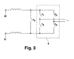
- FIG. 3 shows a detailed representation of an inverter 6.
- the inverter 6 has a full bridge, which consists of four switching elements T1 - T4 designed as transistors. These switching elements T1 - T4 are controlled by the control device 14. To interrupt the power supply to the plasma chamber are various Scenarios conceivable. On the one hand, it is conceivable to switch the switching elements T1 and T3 to short-circuit the current from the DC power supply 3 or to short-circuit the terminals 30, 31 or to connect them to low resistance.
- the switching elements T1, T2 or T3, T4 or all the switching elements T1 - T4 are driven so that they are conductive, the output resonant circuit consisting of the capacitor 9 and the primary inductance 32 of the output transformer 10, shorted, so that in this way the power supply to the plasma chamber is interrupted.
- a switching element T5 can furthermore be arranged between the terminals 30, 31 or at the input of the inverter 6.
- the switching elements T1-T5 can be controlled by the control device 17, in particular by the means 18 for generating a switch-off signal.
Landscapes
- Physics & Mathematics (AREA)
- Engineering & Computer Science (AREA)
- Plasma & Fusion (AREA)
- Chemical & Material Sciences (AREA)
- Analytical Chemistry (AREA)
- Plasma Technology (AREA)
- Arc Welding Control (AREA)
- Investigating, Analyzing Materials By Fluorescence Or Luminescence (AREA)
- Analysing Materials By The Use Of Radiation (AREA)
Priority Applications (7)
| Application Number | Priority Date | Filing Date | Title |
|---|---|---|---|
| AT05006680T ATE362194T1 (de) | 2005-03-26 | 2005-03-26 | Verfahren zur arcerkennung |
| DE502005000705T DE502005000705D1 (de) | 2005-03-26 | 2005-03-26 | Verfahren zur Arcerkennung |
| EP05006680A EP1705687B1 (fr) | 2005-03-26 | 2005-03-26 | Procédé de détection d'arc |
| PL05006680T PL1705687T3 (pl) | 2005-03-26 | 2005-03-26 | Sposób wykrywania łuku |
| JP2006083799A JP4523564B2 (ja) | 2005-03-26 | 2006-03-24 | プラズマプロセスでのアーク識別方法およびプラズマ励起装置 |
| US11/277,460 US7262606B2 (en) | 2005-03-26 | 2006-03-24 | Method of arc detection |
| KR1020060026774A KR100783454B1 (ko) | 2005-03-26 | 2006-03-24 | 아크 탐지의 방법 |
Applications Claiming Priority (1)
| Application Number | Priority Date | Filing Date | Title |
|---|---|---|---|
| EP05006680A EP1705687B1 (fr) | 2005-03-26 | 2005-03-26 | Procédé de détection d'arc |
Publications (2)
| Publication Number | Publication Date |
|---|---|
| EP1705687A1 true EP1705687A1 (fr) | 2006-09-27 |
| EP1705687B1 EP1705687B1 (fr) | 2007-05-09 |
Family
ID=35044559
Family Applications (1)
| Application Number | Title | Priority Date | Filing Date |
|---|---|---|---|
| EP05006680A Expired - Lifetime EP1705687B1 (fr) | 2005-03-26 | 2005-03-26 | Procédé de détection d'arc |
Country Status (6)
| Country | Link |
|---|---|
| EP (1) | EP1705687B1 (fr) |
| JP (1) | JP4523564B2 (fr) |
| KR (1) | KR100783454B1 (fr) |
| AT (1) | ATE362194T1 (fr) |
| DE (1) | DE502005000705D1 (fr) |
| PL (1) | PL1705687T3 (fr) |
Cited By (10)
| Publication number | Priority date | Publication date | Assignee | Title |
|---|---|---|---|---|
| EP1978542A1 (fr) * | 2007-03-08 | 2008-10-08 | HÜTTINGER Elektronik GmbH + Co. KG | Procédé et dispositif destinés à l'extraction de décharges en arc lors du fonctionnement d'un processus plasma |
| US7640120B2 (en) | 2005-12-22 | 2009-12-29 | Huettinger Elektronik Gmbh + Co. Kg | Method and device for detecting arcs |
| US7795817B2 (en) | 2006-11-24 | 2010-09-14 | Huettinger Elektronik Gmbh + Co. Kg | Controlled plasma power supply |
| US7995313B2 (en) | 2006-11-23 | 2011-08-09 | Huettinger Elektronik Gmbh + Co. Kg | Method for operating a plasma process and arc discharge detection device |
| US8007641B2 (en) | 2004-03-25 | 2011-08-30 | Huettinger Elektronik Gmbh + Co. Kg | Method of detecting arc discharges in a plasma process |
| US8085054B2 (en) | 2006-11-28 | 2011-12-27 | Huettinger Elektronik Gmbh + Co. Kg | Detecting arc discharges |
| DE102011112434A1 (de) * | 2011-01-05 | 2012-07-05 | Oerlikon Trading Ag, Trübbach | Blitzdetektion in Beschichtungsanlagen |
| US8735767B2 (en) | 2006-12-14 | 2014-05-27 | Trumpf Huettinger Gmbh + Co. Kg | Responding to arc discharges |
| US10181392B2 (en) | 2013-10-01 | 2019-01-15 | Trumpf Huettinger Gmbh + Co. Kg | Monitoring a discharge in a plasma process |
| US10290477B2 (en) | 2014-02-07 | 2019-05-14 | Trumpf Huettinger Sp. Z O. O. | Monitoring a discharge in a plasma process |
Families Citing this family (5)
| Publication number | Priority date | Publication date | Assignee | Title |
|---|---|---|---|---|
| US8779928B2 (en) * | 2012-05-03 | 2014-07-15 | General Electric Company | Systems and methods to detect generator collector flashover |
| JP5679241B1 (ja) | 2013-09-27 | 2015-03-04 | 株式会社京三製作所 | 電圧形直流電源装置および電圧形直流電源装置の制御方法 |
| EP3054472A1 (fr) * | 2015-02-03 | 2016-08-10 | TRUMPF Huettinger Sp. Z o. o. | Dispositif et procédé de traitement d'arcs |
| EP3609300B1 (fr) * | 2017-04-04 | 2021-06-23 | Fuji Corporation | Dispositif de génération de plasma avec détecteur pour relever un courant circulant à travers un câble de masse |
| KR102208819B1 (ko) * | 2020-12-09 | 2021-01-28 | 주식회사 더블유지에스 | 플라즈마 공정 중 발생하는 아크 현상을 모니터링하기 위한 rf 신호 모니터링 장치 및 시스템 |
Citations (3)
| Publication number | Priority date | Publication date | Assignee | Title |
|---|---|---|---|---|
| WO1999014394A1 (fr) * | 1997-09-17 | 1999-03-25 | Tokyo Electron Limited | Dispositif et procede de detection et de prevention de formation d'arc dans un systeme a plasma haute frequence |
| US6420863B1 (en) * | 1998-10-22 | 2002-07-16 | Fraunhofer-Gesellschaft zur Förderung der angewandten Forschung e.V | Method for monitoring alternating current discharge on a double electrode and apparatus |
| EP1441576A1 (fr) * | 2001-10-22 | 2004-07-28 | Shibaura Mechatronics Corporation | Procede permettant d'evaluer un arc de dispositif de decharge luminescente et suppresseur de decharge d'arc haute frequence |
Family Cites Families (3)
| Publication number | Priority date | Publication date | Assignee | Title |
|---|---|---|---|---|
| DE4326100B4 (de) * | 1993-08-04 | 2006-03-23 | Unaxis Deutschland Holding Gmbh | Verfahren und Vorrichtung zum Beschichten von Substraten in einer Vakuumkammer, mit einer Einrichtung zur Erkennung und Unterdrückung von unerwünschten Lichtbögen |
| DE4441206C2 (de) * | 1994-11-19 | 1996-09-26 | Leybold Ag | Einrichtung für die Unterdrückung von Überschlägen in Kathoden-Zerstäubungseinrichtungen |
| KR100785865B1 (ko) * | 2005-02-24 | 2007-12-21 | 이엔테크놀로지 주식회사 | 플라즈마 전원장치용 아크 검출 및 아크 에너지 저감 회로 |
-
2005
- 2005-03-26 EP EP05006680A patent/EP1705687B1/fr not_active Expired - Lifetime
- 2005-03-26 AT AT05006680T patent/ATE362194T1/de not_active IP Right Cessation
- 2005-03-26 DE DE502005000705T patent/DE502005000705D1/de not_active Expired - Lifetime
- 2005-03-26 PL PL05006680T patent/PL1705687T3/pl unknown
-
2006
- 2006-03-24 KR KR1020060026774A patent/KR100783454B1/ko not_active Expired - Lifetime
- 2006-03-24 JP JP2006083799A patent/JP4523564B2/ja not_active Expired - Fee Related
Patent Citations (3)
| Publication number | Priority date | Publication date | Assignee | Title |
|---|---|---|---|---|
| WO1999014394A1 (fr) * | 1997-09-17 | 1999-03-25 | Tokyo Electron Limited | Dispositif et procede de detection et de prevention de formation d'arc dans un systeme a plasma haute frequence |
| US6420863B1 (en) * | 1998-10-22 | 2002-07-16 | Fraunhofer-Gesellschaft zur Förderung der angewandten Forschung e.V | Method for monitoring alternating current discharge on a double electrode and apparatus |
| EP1441576A1 (fr) * | 2001-10-22 | 2004-07-28 | Shibaura Mechatronics Corporation | Procede permettant d'evaluer un arc de dispositif de decharge luminescente et suppresseur de decharge d'arc haute frequence |
Cited By (14)
| Publication number | Priority date | Publication date | Assignee | Title |
|---|---|---|---|---|
| US9484189B2 (en) | 2004-03-25 | 2016-11-01 | Trumpf Huettinger Gmbh + Co. Kg | Method of detecting arc discharge in a plasma process |
| US8007641B2 (en) | 2004-03-25 | 2011-08-30 | Huettinger Elektronik Gmbh + Co. Kg | Method of detecting arc discharges in a plasma process |
| US7640120B2 (en) | 2005-12-22 | 2009-12-29 | Huettinger Elektronik Gmbh + Co. Kg | Method and device for detecting arcs |
| US7995313B2 (en) | 2006-11-23 | 2011-08-09 | Huettinger Elektronik Gmbh + Co. Kg | Method for operating a plasma process and arc discharge detection device |
| US8044595B2 (en) | 2006-11-23 | 2011-10-25 | Huettinger Elektronik Gmbh + Co. Kg | Operating a plasma process |
| US7795817B2 (en) | 2006-11-24 | 2010-09-14 | Huettinger Elektronik Gmbh + Co. Kg | Controlled plasma power supply |
| US8110992B2 (en) | 2006-11-24 | 2012-02-07 | Huettinger Elektronik Gmbh + Co. Kg | Controlled plasma power supply |
| US8085054B2 (en) | 2006-11-28 | 2011-12-27 | Huettinger Elektronik Gmbh + Co. Kg | Detecting arc discharges |
| US8735767B2 (en) | 2006-12-14 | 2014-05-27 | Trumpf Huettinger Gmbh + Co. Kg | Responding to arc discharges |
| US7929261B2 (en) | 2007-03-08 | 2011-04-19 | Huettinger Elektronik Gmbh + Co. Kg | Suppressing arc discharges |
| EP1978542A1 (fr) * | 2007-03-08 | 2008-10-08 | HÜTTINGER Elektronik GmbH + Co. KG | Procédé et dispositif destinés à l'extraction de décharges en arc lors du fonctionnement d'un processus plasma |
| DE102011112434A1 (de) * | 2011-01-05 | 2012-07-05 | Oerlikon Trading Ag, Trübbach | Blitzdetektion in Beschichtungsanlagen |
| US10181392B2 (en) | 2013-10-01 | 2019-01-15 | Trumpf Huettinger Gmbh + Co. Kg | Monitoring a discharge in a plasma process |
| US10290477B2 (en) | 2014-02-07 | 2019-05-14 | Trumpf Huettinger Sp. Z O. O. | Monitoring a discharge in a plasma process |
Also Published As
| Publication number | Publication date |
|---|---|
| PL1705687T3 (pl) | 2007-09-28 |
| JP2006278335A (ja) | 2006-10-12 |
| DE502005000705D1 (de) | 2007-06-21 |
| KR100783454B1 (ko) | 2007-12-07 |
| KR20060103404A (ko) | 2006-09-29 |
| EP1705687B1 (fr) | 2007-05-09 |
| ATE362194T1 (de) | 2007-06-15 |
| JP4523564B2 (ja) | 2010-08-11 |
Similar Documents
| Publication | Publication Date | Title |
|---|---|---|
| EP1705687B1 (fr) | Procédé de détection d'arc | |
| EP1801946B1 (fr) | Procédé et dispositif de détection d'arc dans un procédé plasma | |
| EP2457314B1 (fr) | Procédé et circuit pour l'amélioration de facteur de puissance | |
| DE202018006714U1 (de) | Leistungswandlereinheit, Plasmabearbeitungseinrichtung und Steuereinrichtung zur Steuerung mehrerer Plasmaprozesse | |
| EP2174338B1 (fr) | Procédé d'utilisation d'un dispositif d'alimentation en plasma et dispositif d'alimentation en plasma | |
| DE102013110883B3 (de) | Vorrichtung und Verfahren zur Überwachung einer Entladung in einem Plasmaprozess | |
| DE202018006711U1 (de) | Leistungswandlereinheit, Plasmabearbeitungseinrichtung und Steuereinrichtung zur Steuerung mehrerer Plasmaprozesse | |
| DE19848636C2 (de) | Verfahren zur Überwachung einer Wechselspannungs-Entladung an einer Doppelelektrode | |
| EP0954876A1 (fr) | Procede et systeme d'exploitation de decharges de magnetrons | |
| DE112010005683B4 (de) | Funkenerosionssteuervorrichtung | |
| CH678825A5 (fr) | ||
| DE3208673C2 (fr) | ||
| DE112008003662B4 (de) | Elektrische Entladungsbearbeitungsvorrichtung und elektrisches Entladungsbearbeitungsverfahren | |
| DE102016122964A1 (de) | System und Verfahren für ein Leistungswandlungssystem | |
| DE4302404C2 (de) | Schaltungsanordnung zur Stromversorgung einer Funkenerodiermaschine | |
| EP0710429B1 (fr) | Procede permettant d'adapter le generateur dans des processus bipolaires de decharge par effluves basse pression | |
| WO2017084857A1 (fr) | Procédé de détection d'une défaillance dans un groupe générateur | |
| DE112017005583B4 (de) | Stromversorgungs-Steuervorrichtung für eine Funkenerosionsmaschine | |
| WO2002033716A1 (fr) | Procede et dispositif pour reduire l'usure des contacts d'un appareil de coupure | |
| DE102005003672A1 (de) | Hochfrequenz-Impulsoszillator | |
| EP0458794A1 (fr) | Procede et dispositif pour commander des gradateurs de courant alternatif monophases ou polyphases. | |
| EP2811810B1 (fr) | Procédé de détermination de courant de crête et dispositif de chauffage à induction | |
| EP1624546B1 (fr) | Dispositif et méthode pour produire une décharge Corona | |
| EP0783702B1 (fr) | Procede et dispositif de mesure d'impedance dans des reseaux a courant alternatif, ainsi que procede et dispositif pour empecher la formation de reseaux separes | |
| EP4523239A1 (fr) | Ensemble d'alimentation en énergie, dispositif de génération de plasma et procédé de commande d'une pluralité de processus au plasma |
Legal Events
| Date | Code | Title | Description |
|---|---|---|---|
| PUAI | Public reference made under article 153(3) epc to a published international application that has entered the european phase |
Free format text: ORIGINAL CODE: 0009012 |
|
| 17P | Request for examination filed |
Effective date: 20060511 |
|
| AK | Designated contracting states |
Kind code of ref document: A1 Designated state(s): AT BE BG CH CY CZ DE DK EE ES FI FR GB GR HU IE IS IT LI LT LU MC NL PL PT RO SE SI SK TR |
|
| AX | Request for extension of the european patent |
Extension state: AL BA HR LV MK YU |
|
| RAP1 | Party data changed (applicant data changed or rights of an application transferred) |
Owner name: HUETTINGER ELEKTRONIK GMBH + CO. KG |
|
| GRAP | Despatch of communication of intention to grant a patent |
Free format text: ORIGINAL CODE: EPIDOSNIGR1 |
|
| GRAS | Grant fee paid |
Free format text: ORIGINAL CODE: EPIDOSNIGR3 |
|
| GRAA | (expected) grant |
Free format text: ORIGINAL CODE: 0009210 |
|
| AK | Designated contracting states |
Kind code of ref document: B1 Designated state(s): AT BE BG CH CY CZ DE DK EE ES FI FR GB GR HU IE IS IT LI LT LU MC NL PL PT RO SE SI SK TR |
|
| PG25 | Lapsed in a contracting state [announced via postgrant information from national office to epo] |
Ref country code: FI Free format text: LAPSE BECAUSE OF FAILURE TO SUBMIT A TRANSLATION OF THE DESCRIPTION OR TO PAY THE FEE WITHIN THE PRESCRIBED TIME-LIMIT Effective date: 20070509 |
|
| REG | Reference to a national code |
Ref country code: GB Ref legal event code: FG4D Free format text: NOT ENGLISH |
|
| AKX | Designation fees paid |
Designated state(s): AT BE BG CH CY CZ DE DK EE ES FI FR GB GR HU IE IS IT LI LT LU MC NL PL PT RO SE SI SK TR |
|
| REG | Reference to a national code |
Ref country code: CH Ref legal event code: EP |
|
| REG | Reference to a national code |
Ref country code: IE Ref legal event code: FG4D Free format text: LANGUAGE OF EP DOCUMENT: GERMAN |
|
| REF | Corresponds to: |
Ref document number: 502005000705 Country of ref document: DE Date of ref document: 20070621 Kind code of ref document: P |
|
| PG25 | Lapsed in a contracting state [announced via postgrant information from national office to epo] |
Ref country code: SE Free format text: LAPSE BECAUSE OF FAILURE TO SUBMIT A TRANSLATION OF THE DESCRIPTION OR TO PAY THE FEE WITHIN THE PRESCRIBED TIME-LIMIT Effective date: 20070809 |
|
| PG25 | Lapsed in a contracting state [announced via postgrant information from national office to epo] |
Ref country code: ES Free format text: LAPSE BECAUSE OF FAILURE TO SUBMIT A TRANSLATION OF THE DESCRIPTION OR TO PAY THE FEE WITHIN THE PRESCRIBED TIME-LIMIT Effective date: 20070820 |
|
| GBT | Gb: translation of ep patent filed (gb section 77(6)(a)/1977) |
Effective date: 20070813 |
|
| PG25 | Lapsed in a contracting state [announced via postgrant information from national office to epo] |
Ref country code: IS Free format text: LAPSE BECAUSE OF FAILURE TO SUBMIT A TRANSLATION OF THE DESCRIPTION OR TO PAY THE FEE WITHIN THE PRESCRIBED TIME-LIMIT Effective date: 20070909 |
|
| ET | Fr: translation filed | ||
| REG | Reference to a national code |
Ref country code: PL Ref legal event code: T3 |
|
| NLV1 | Nl: lapsed or annulled due to failure to fulfill the requirements of art. 29p and 29m of the patents act | ||
| REG | Reference to a national code |
Ref country code: IE Ref legal event code: FD4D |
|
| PG25 | Lapsed in a contracting state [announced via postgrant information from national office to epo] |
Ref country code: BG Free format text: LAPSE BECAUSE OF FAILURE TO SUBMIT A TRANSLATION OF THE DESCRIPTION OR TO PAY THE FEE WITHIN THE PRESCRIBED TIME-LIMIT Effective date: 20070809 Ref country code: DK Free format text: LAPSE BECAUSE OF FAILURE TO SUBMIT A TRANSLATION OF THE DESCRIPTION OR TO PAY THE FEE WITHIN THE PRESCRIBED TIME-LIMIT Effective date: 20070509 Ref country code: SI Free format text: LAPSE BECAUSE OF FAILURE TO SUBMIT A TRANSLATION OF THE DESCRIPTION OR TO PAY THE FEE WITHIN THE PRESCRIBED TIME-LIMIT Effective date: 20070509 Ref country code: NL Free format text: LAPSE BECAUSE OF FAILURE TO SUBMIT A TRANSLATION OF THE DESCRIPTION OR TO PAY THE FEE WITHIN THE PRESCRIBED TIME-LIMIT Effective date: 20070509 Ref country code: PT Free format text: LAPSE BECAUSE OF FAILURE TO SUBMIT A TRANSLATION OF THE DESCRIPTION OR TO PAY THE FEE WITHIN THE PRESCRIBED TIME-LIMIT Effective date: 20071009 Ref country code: CZ Free format text: LAPSE BECAUSE OF FAILURE TO SUBMIT A TRANSLATION OF THE DESCRIPTION OR TO PAY THE FEE WITHIN THE PRESCRIBED TIME-LIMIT Effective date: 20070509 Ref country code: IE Free format text: LAPSE BECAUSE OF FAILURE TO SUBMIT A TRANSLATION OF THE DESCRIPTION OR TO PAY THE FEE WITHIN THE PRESCRIBED TIME-LIMIT Effective date: 20070509 |
|
| PG25 | Lapsed in a contracting state [announced via postgrant information from national office to epo] |
Ref country code: SK Free format text: LAPSE BECAUSE OF FAILURE TO SUBMIT A TRANSLATION OF THE DESCRIPTION OR TO PAY THE FEE WITHIN THE PRESCRIBED TIME-LIMIT Effective date: 20070509 Ref country code: LT Free format text: LAPSE BECAUSE OF FAILURE TO SUBMIT A TRANSLATION OF THE DESCRIPTION OR TO PAY THE FEE WITHIN THE PRESCRIBED TIME-LIMIT Effective date: 20070509 |
|
| PLBE | No opposition filed within time limit |
Free format text: ORIGINAL CODE: 0009261 |
|
| STAA | Information on the status of an ep patent application or granted ep patent |
Free format text: STATUS: NO OPPOSITION FILED WITHIN TIME LIMIT |
|
| 26N | No opposition filed |
Effective date: 20080212 |
|
| PG25 | Lapsed in a contracting state [announced via postgrant information from national office to epo] |
Ref country code: GR Free format text: LAPSE BECAUSE OF FAILURE TO SUBMIT A TRANSLATION OF THE DESCRIPTION OR TO PAY THE FEE WITHIN THE PRESCRIBED TIME-LIMIT Effective date: 20070810 |
|
| PG25 | Lapsed in a contracting state [announced via postgrant information from national office to epo] |
Ref country code: RO Free format text: LAPSE BECAUSE OF FAILURE TO SUBMIT A TRANSLATION OF THE DESCRIPTION OR TO PAY THE FEE WITHIN THE PRESCRIBED TIME-LIMIT Effective date: 20070509 |
|
| PG25 | Lapsed in a contracting state [announced via postgrant information from national office to epo] |
Ref country code: MC Free format text: LAPSE BECAUSE OF NON-PAYMENT OF DUE FEES Effective date: 20080331 |
|
| PG25 | Lapsed in a contracting state [announced via postgrant information from national office to epo] |
Ref country code: EE Free format text: LAPSE BECAUSE OF FAILURE TO SUBMIT A TRANSLATION OF THE DESCRIPTION OR TO PAY THE FEE WITHIN THE PRESCRIBED TIME-LIMIT Effective date: 20070509 |
|
| PGFP | Annual fee paid to national office [announced via postgrant information from national office to epo] |
Ref country code: AT Payment date: 20090323 Year of fee payment: 5 |
|
| PGFP | Annual fee paid to national office [announced via postgrant information from national office to epo] |
Ref country code: PL Payment date: 20090318 Year of fee payment: 5 |
|
| PG25 | Lapsed in a contracting state [announced via postgrant information from national office to epo] |
Ref country code: CY Free format text: LAPSE BECAUSE OF FAILURE TO SUBMIT A TRANSLATION OF THE DESCRIPTION OR TO PAY THE FEE WITHIN THE PRESCRIBED TIME-LIMIT Effective date: 20070509 |
|
| PGFP | Annual fee paid to national office [announced via postgrant information from national office to epo] |
Ref country code: BE Payment date: 20090330 Year of fee payment: 5 |
|
| PGFP | Annual fee paid to national office [announced via postgrant information from national office to epo] |
Ref country code: IT Payment date: 20090328 Year of fee payment: 5 |
|
| PG25 | Lapsed in a contracting state [announced via postgrant information from national office to epo] |
Ref country code: HU Free format text: LAPSE BECAUSE OF FAILURE TO SUBMIT A TRANSLATION OF THE DESCRIPTION OR TO PAY THE FEE WITHIN THE PRESCRIBED TIME-LIMIT Effective date: 20071110 Ref country code: LU Free format text: LAPSE BECAUSE OF NON-PAYMENT OF DUE FEES Effective date: 20080326 |
|
| PG25 | Lapsed in a contracting state [announced via postgrant information from national office to epo] |
Ref country code: TR Free format text: LAPSE BECAUSE OF FAILURE TO SUBMIT A TRANSLATION OF THE DESCRIPTION OR TO PAY THE FEE WITHIN THE PRESCRIBED TIME-LIMIT Effective date: 20070509 |
|
| BERE | Be: lapsed |
Owner name: HUTTINGER ELEKTRONIK G.M.B.H. + CO. KG Effective date: 20100331 |
|
| PG25 | Lapsed in a contracting state [announced via postgrant information from national office to epo] |
Ref country code: AT Free format text: LAPSE BECAUSE OF NON-PAYMENT OF DUE FEES Effective date: 20100326 |
|
| PG25 | Lapsed in a contracting state [announced via postgrant information from national office to epo] |
Ref country code: BE Free format text: LAPSE BECAUSE OF NON-PAYMENT OF DUE FEES Effective date: 20100331 |
|
| PG25 | Lapsed in a contracting state [announced via postgrant information from national office to epo] |
Ref country code: IT Free format text: LAPSE BECAUSE OF NON-PAYMENT OF DUE FEES Effective date: 20100326 |
|
| REG | Reference to a national code |
Ref country code: PL Ref legal event code: LAPE |
|
| PG25 | Lapsed in a contracting state [announced via postgrant information from national office to epo] |
Ref country code: PL Free format text: LAPSE BECAUSE OF NON-PAYMENT OF DUE FEES Effective date: 20100326 |
|
| REG | Reference to a national code |
Ref country code: CH Ref legal event code: PFA Owner name: TRUMPF HUETTINGER GMBH + CO. KG, DE Free format text: FORMER OWNER: HUETTINGER ELEKTRONIK GMBH + CO. KG, DE |
|
| REG | Reference to a national code |
Ref country code: DE Ref legal event code: R082 Ref document number: 502005000705 Country of ref document: DE Representative=s name: KOHLER SCHMID MOEBUS PATENTANWAELTE, DE Effective date: 20130801 Ref country code: DE Ref legal event code: R081 Ref document number: 502005000705 Country of ref document: DE Owner name: TRUMPF HUETTINGER GMBH + CO. KG, DE Free format text: FORMER OWNER: HUETTINGER ELEKTRONIK GMBH + CO. KG, 79111 FREIBURG, DE Effective date: 20130801 Ref country code: DE Ref legal event code: R082 Ref document number: 502005000705 Country of ref document: DE Representative=s name: KOHLER SCHMID MOEBUS PATENTANWAELTE PARTNERSCH, DE Effective date: 20130801 |
|
| REG | Reference to a national code |
Ref country code: FR Ref legal event code: PLFP Year of fee payment: 11 |
|
| PGFP | Annual fee paid to national office [announced via postgrant information from national office to epo] |
Ref country code: CH Payment date: 20150325 Year of fee payment: 11 |
|
| PGFP | Annual fee paid to national office [announced via postgrant information from national office to epo] |
Ref country code: FR Payment date: 20150319 Year of fee payment: 11 Ref country code: GB Payment date: 20150324 Year of fee payment: 11 |
|
| REG | Reference to a national code |
Ref country code: CH Ref legal event code: PL |
|
| GBPC | Gb: european patent ceased through non-payment of renewal fee |
Effective date: 20160326 |
|
| REG | Reference to a national code |
Ref country code: FR Ref legal event code: ST Effective date: 20161130 |
|
| PG25 | Lapsed in a contracting state [announced via postgrant information from national office to epo] |
Ref country code: LI Free format text: LAPSE BECAUSE OF NON-PAYMENT OF DUE FEES Effective date: 20160331 Ref country code: FR Free format text: LAPSE BECAUSE OF NON-PAYMENT OF DUE FEES Effective date: 20160331 Ref country code: GB Free format text: LAPSE BECAUSE OF NON-PAYMENT OF DUE FEES Effective date: 20160326 Ref country code: CH Free format text: LAPSE BECAUSE OF NON-PAYMENT OF DUE FEES Effective date: 20160331 |
|
| PGFP | Annual fee paid to national office [announced via postgrant information from national office to epo] |
Ref country code: DE Payment date: 20240320 Year of fee payment: 20 |
|
| REG | Reference to a national code |
Ref country code: DE Ref legal event code: R071 Ref document number: 502005000705 Country of ref document: DE |