EP1705724B1 - Actionneur piézo-électrique et dispositif d'éjection de liquide - Google Patents
Actionneur piézo-électrique et dispositif d'éjection de liquide Download PDFInfo
- Publication number
- EP1705724B1 EP1705724B1 EP20060111701 EP06111701A EP1705724B1 EP 1705724 B1 EP1705724 B1 EP 1705724B1 EP 20060111701 EP20060111701 EP 20060111701 EP 06111701 A EP06111701 A EP 06111701A EP 1705724 B1 EP1705724 B1 EP 1705724B1
- Authority
- EP
- European Patent Office
- Prior art keywords
- piezoelectric
- ceramic
- piezoelectric ceramic
- ratio
- piezoelectric actuator
- Prior art date
- Legal status (The legal status is an assumption and is not a legal conclusion. Google has not performed a legal analysis and makes no representation as to the accuracy of the status listed.)
- Ceased
Links
- 239000007788 liquid Substances 0.000 title claims description 32
- 238000007599 discharging Methods 0.000 title claims description 17
- 239000000919 ceramic Substances 0.000 claims description 101
- 238000006073 displacement reaction Methods 0.000 claims description 42
- 239000013078 crystal Substances 0.000 claims description 9
- HFGPZNIAWCZYJU-UHFFFAOYSA-N lead zirconate titanate Chemical compound [O-2].[O-2].[O-2].[O-2].[O-2].[Ti+4].[Zr+4].[Pb+2] HFGPZNIAWCZYJU-UHFFFAOYSA-N 0.000 claims description 6
- 229910052712 strontium Inorganic materials 0.000 claims description 4
- 229910052769 Ytterbium Inorganic materials 0.000 claims description 3
- 229910052787 antimony Inorganic materials 0.000 claims description 3
- 229910052758 niobium Inorganic materials 0.000 claims description 3
- 230000010287 polarization Effects 0.000 claims description 3
- 229910052714 tellurium Inorganic materials 0.000 claims description 3
- 229910052725 zinc Inorganic materials 0.000 claims description 3
- 229910052745 lead Inorganic materials 0.000 claims description 2
- 229910052719 titanium Inorganic materials 0.000 claims description 2
- 229910052726 zirconium Inorganic materials 0.000 claims description 2
- 239000000463 material Substances 0.000 description 16
- 230000035882 stress Effects 0.000 description 13
- 239000000203 mixture Substances 0.000 description 9
- 239000000758 substrate Substances 0.000 description 9
- 238000010586 diagram Methods 0.000 description 7
- 239000000843 powder Substances 0.000 description 7
- 238000005245 sintering Methods 0.000 description 7
- 238000002441 X-ray diffraction Methods 0.000 description 5
- 230000006866 deterioration Effects 0.000 description 5
- 238000007639 printing Methods 0.000 description 5
- 150000001875 compounds Chemical class 0.000 description 4
- NKZSPGSOXYXWQA-UHFFFAOYSA-N dioxido(oxo)titanium;lead(2+) Chemical compound [Pb+2].[O-][Ti]([O-])=O NKZSPGSOXYXWQA-UHFFFAOYSA-N 0.000 description 4
- 238000000034 method Methods 0.000 description 4
- KFZMGEQAYNKOFK-UHFFFAOYSA-N Isopropanol Chemical compound CC(C)O KFZMGEQAYNKOFK-UHFFFAOYSA-N 0.000 description 3
- 239000011230 binding agent Substances 0.000 description 3
- 230000000694 effects Effects 0.000 description 3
- 238000011156 evaluation Methods 0.000 description 3
- SOGAXMICEFXMKE-UHFFFAOYSA-N Butylmethacrylate Chemical compound CCCCOC(=O)C(C)=C SOGAXMICEFXMKE-UHFFFAOYSA-N 0.000 description 2
- 229910001252 Pd alloy Inorganic materials 0.000 description 2
- 239000000853 adhesive Substances 0.000 description 2
- 230000001070 adhesive effect Effects 0.000 description 2
- 239000012298 atmosphere Substances 0.000 description 2
- JRPBQTZRNDNNOP-UHFFFAOYSA-N barium titanate Chemical compound [Ba+2].[Ba+2].[O-][Ti]([O-])([O-])[O-] JRPBQTZRNDNNOP-UHFFFAOYSA-N 0.000 description 2
- 229910002113 barium titanate Inorganic materials 0.000 description 2
- 238000005304 joining Methods 0.000 description 2
- 229910052451 lead zirconate titanate Inorganic materials 0.000 description 2
- 238000004519 manufacturing process Methods 0.000 description 2
- SWELZOZIOHGSPA-UHFFFAOYSA-N palladium silver Chemical compound [Pd].[Ag] SWELZOZIOHGSPA-UHFFFAOYSA-N 0.000 description 2
- 238000009774 resonance method Methods 0.000 description 2
- 239000002002 slurry Substances 0.000 description 2
- 238000012360 testing method Methods 0.000 description 2
- XLYOFNOQVPJJNP-UHFFFAOYSA-N water Substances O XLYOFNOQVPJJNP-UHFFFAOYSA-N 0.000 description 2
- QGZKDVFQNNGYKY-UHFFFAOYSA-O Ammonium Chemical compound [NH4+] QGZKDVFQNNGYKY-UHFFFAOYSA-O 0.000 description 1
- 229910052581 Si3N4 Inorganic materials 0.000 description 1
- 230000001133 acceleration Effects 0.000 description 1
- 239000000654 additive Substances 0.000 description 1
- 239000003513 alkali Substances 0.000 description 1
- QVGXLLKOCUKJST-UHFFFAOYSA-N atomic oxygen Chemical compound [O] QVGXLLKOCUKJST-UHFFFAOYSA-N 0.000 description 1
- 229910052788 barium Inorganic materials 0.000 description 1
- 230000008602 contraction Effects 0.000 description 1
- PMHQVHHXPFUNSP-UHFFFAOYSA-M copper(1+);methylsulfanylmethane;bromide Chemical compound Br[Cu].CSC PMHQVHHXPFUNSP-UHFFFAOYSA-M 0.000 description 1
- RKTYLMNFRDHKIL-UHFFFAOYSA-N copper;5,10,15,20-tetraphenylporphyrin-22,24-diide Chemical compound [Cu+2].C1=CC(C(=C2C=CC([N-]2)=C(C=2C=CC=CC=2)C=2C=CC(N=2)=C(C=2C=CC=CC=2)C2=CC=C3[N-]2)C=2C=CC=CC=2)=NC1=C3C1=CC=CC=C1 RKTYLMNFRDHKIL-UHFFFAOYSA-N 0.000 description 1
- 230000007547 defect Effects 0.000 description 1
- 239000002270 dispersing agent Substances 0.000 description 1
- 238000007606 doctor blade method Methods 0.000 description 1
- 239000002003 electrode paste Substances 0.000 description 1
- 230000002708 enhancing effect Effects 0.000 description 1
- 230000008020 evaporation Effects 0.000 description 1
- 238000001704 evaporation Methods 0.000 description 1
- 230000001747 exhibiting effect Effects 0.000 description 1
- 239000000446 fuel Substances 0.000 description 1
- 238000010438 heat treatment Methods 0.000 description 1
- CPLXHLVBOLITMK-UHFFFAOYSA-N magnesium oxide Inorganic materials [Mg]=O CPLXHLVBOLITMK-UHFFFAOYSA-N 0.000 description 1
- 239000000395 magnesium oxide Substances 0.000 description 1
- AXZKOIWUVFPNLO-UHFFFAOYSA-N magnesium;oxygen(2-) Chemical compound [O-2].[Mg+2] AXZKOIWUVFPNLO-UHFFFAOYSA-N 0.000 description 1
- 238000005259 measurement Methods 0.000 description 1
- 230000007246 mechanism Effects 0.000 description 1
- 229910052751 metal Inorganic materials 0.000 description 1
- 239000002184 metal Substances 0.000 description 1
- 238000012986 modification Methods 0.000 description 1
- 230000004048 modification Effects 0.000 description 1
- TWNQGVIAIRXVLR-UHFFFAOYSA-N oxo(oxoalumanyloxy)alumane Chemical compound O=[Al]O[Al]=O TWNQGVIAIRXVLR-UHFFFAOYSA-N 0.000 description 1
- 229910052760 oxygen Inorganic materials 0.000 description 1
- 239000001301 oxygen Substances 0.000 description 1
- RVTZCBVAJQQJTK-UHFFFAOYSA-N oxygen(2-);zirconium(4+) Chemical compound [O-2].[O-2].[Zr+4] RVTZCBVAJQQJTK-UHFFFAOYSA-N 0.000 description 1
- KDLHZDBZIXYQEI-UHFFFAOYSA-N palladium Substances [Pd] KDLHZDBZIXYQEI-UHFFFAOYSA-N 0.000 description 1
- 229920005646 polycarboxylate Polymers 0.000 description 1
- 238000002360 preparation method Methods 0.000 description 1
- 238000003825 pressing Methods 0.000 description 1
- 230000008569 process Effects 0.000 description 1
- 230000009467 reduction Effects 0.000 description 1
- 238000011160 research Methods 0.000 description 1
- 230000004044 response Effects 0.000 description 1
- 238000007650 screen-printing Methods 0.000 description 1
- 239000004065 semiconductor Substances 0.000 description 1
- HQVNEWCFYHHQES-UHFFFAOYSA-N silicon nitride Chemical compound N12[Si]34N5[Si]62N3[Si]51N64 HQVNEWCFYHHQES-UHFFFAOYSA-N 0.000 description 1
- 229910052709 silver Inorganic materials 0.000 description 1
- 239000004332 silver Substances 0.000 description 1
- 238000005476 soldering Methods 0.000 description 1
- 239000006104 solid solution Substances 0.000 description 1
- 239000002904 solvent Substances 0.000 description 1
- 230000007480 spreading Effects 0.000 description 1
- 238000003892 spreading Methods 0.000 description 1
- 230000008646 thermal stress Effects 0.000 description 1
- 229910052721 tungsten Inorganic materials 0.000 description 1
- 239000010937 tungsten Substances 0.000 description 1
- 229910001928 zirconium oxide Inorganic materials 0.000 description 1
Images
Classifications
-
- B—PERFORMING OPERATIONS; TRANSPORTING
- B41—PRINTING; LINING MACHINES; TYPEWRITERS; STAMPS
- B41J—TYPEWRITERS; SELECTIVE PRINTING MECHANISMS, i.e. MECHANISMS PRINTING OTHERWISE THAN FROM A FORME; CORRECTION OF TYPOGRAPHICAL ERRORS
- B41J2/00—Typewriters or selective printing mechanisms characterised by the printing or marking process for which they are designed
- B41J2/005—Typewriters or selective printing mechanisms characterised by the printing or marking process for which they are designed characterised by bringing liquid or particles selectively into contact with a printing material
- B41J2/01—Ink jet
- B41J2/135—Nozzles
- B41J2/14—Structure thereof only for on-demand ink jet heads
- B41J2/14201—Structure of print heads with piezoelectric elements
- B41J2/14233—Structure of print heads with piezoelectric elements of film type, deformed by bending and disposed on a diaphragm
-
- H—ELECTRICITY
- H10—SEMICONDUCTOR DEVICES; ELECTRIC SOLID-STATE DEVICES NOT OTHERWISE PROVIDED FOR
- H10N—ELECTRIC SOLID-STATE DEVICES NOT OTHERWISE PROVIDED FOR
- H10N30/00—Piezoelectric or electrostrictive devices
- H10N30/20—Piezoelectric or electrostrictive devices with electrical input and mechanical output, e.g. functioning as actuators or vibrators
- H10N30/204—Piezoelectric or electrostrictive devices with electrical input and mechanical output, e.g. functioning as actuators or vibrators using bending displacement, e.g. unimorph, bimorph or multimorph cantilever or membrane benders
- H10N30/2047—Membrane type
-
- H—ELECTRICITY
- H10—SEMICONDUCTOR DEVICES; ELECTRIC SOLID-STATE DEVICES NOT OTHERWISE PROVIDED FOR
- H10N—ELECTRIC SOLID-STATE DEVICES NOT OTHERWISE PROVIDED FOR
- H10N30/00—Piezoelectric or electrostrictive devices
- H10N30/80—Constructional details
- H10N30/85—Piezoelectric or electrostrictive active materials
- H10N30/853—Ceramic compositions
-
- B—PERFORMING OPERATIONS; TRANSPORTING
- B41—PRINTING; LINING MACHINES; TYPEWRITERS; STAMPS
- B41J—TYPEWRITERS; SELECTIVE PRINTING MECHANISMS, i.e. MECHANISMS PRINTING OTHERWISE THAN FROM A FORME; CORRECTION OF TYPOGRAPHICAL ERRORS
- B41J2/00—Typewriters or selective printing mechanisms characterised by the printing or marking process for which they are designed
- B41J2/005—Typewriters or selective printing mechanisms characterised by the printing or marking process for which they are designed characterised by bringing liquid or particles selectively into contact with a printing material
- B41J2/01—Ink jet
- B41J2/135—Nozzles
- B41J2/14—Structure thereof only for on-demand ink jet heads
- B41J2/14201—Structure of print heads with piezoelectric elements
- B41J2/14233—Structure of print heads with piezoelectric elements of film type, deformed by bending and disposed on a diaphragm
- B41J2002/14266—Sheet-like thin film type piezoelectric element
-
- B—PERFORMING OPERATIONS; TRANSPORTING
- B41—PRINTING; LINING MACHINES; TYPEWRITERS; STAMPS
- B41J—TYPEWRITERS; SELECTIVE PRINTING MECHANISMS, i.e. MECHANISMS PRINTING OTHERWISE THAN FROM A FORME; CORRECTION OF TYPOGRAPHICAL ERRORS
- B41J2202/00—Embodiments of or processes related to ink-jet or thermal heads
- B41J2202/01—Embodiments of or processes related to ink-jet heads
- B41J2202/03—Specific materials used
Definitions
- the present invention relates to a piezoelectric actuator and a discharging device, and in particular, to a piezoelectric actuator and discharging device which are appropriate for fuel injectors, inkjet printers, piezoelectric resonators, oscillators, ultrasonic motors, ultrasonic transducers, filters, piezoelectric sensors, such as acceleration sensors, knocking sensors and AE sensors, and are appropriate for use as printing heads using, specifically, spreading vibration, extensional vibration and thickness longitudinal vibration.
- piezoelectric actuators for example, have a very high response speed to electrical signals in the microseconds, and therefore, are applied as piezoelectric actuators for the positioning of XY stages in semiconductor manufacturing units, piezoelectric actuators which are used for the printing head of inkjet printers and the like.
- piezoelectric actuators which are used for the printing head of inkjet printers and the like.
- recent increase in the speed of color printers, as well as reduction in price make high the requirement of using piezoelectric actuators for discharging ink in inkjet printers and the like.
- a piezoelectric element is used in such piezoelectric actuators.
- a so-called unimorph type piezoelectric actuator having a ceramic substrate which works as a ceramic diaphragm, and a first electrode layer, a piezoelectric layer and a second electrode layer which are provided on top of the ceramic substrate in this order, has been proposed (see, for example, No. WO02/073710 )
- the piezoelectric element (displacement element) is formed of the first electric layer and the second electric layer sandwiching the above described piezoelectric layer.
- an adhesive which is hardened at a high temperature for example, not lower than 100°C is used.
- the coefficient of linear thermal expansion is different between the ceramic substrate and the displacement element, and therefore, heating at the time of adhesion causes compressive stress in the displacement element, and a problem arises, such that this compressive stress significantly causes the piezoelectric properties of the displacement element to significantly deteriorate.
- the present invention provides a piezoelectric actuator and a liquid discharging device which have excellent durability when driven.
- the present inventors conducted diligent research in order to solve the above described problem, and as a result, discovered the following. That is to say, it is indispensable to use zonal rotational distortion in the piezoelectric material in order to gain high displacement properties. In order to gain large zonal rotational distortion in this manner, it is effective to use the composition on the rhombohedral crystal side in the vicinity of the morphotropic phase boundary (MPB) or to add a trivalent, pentavalent or higher donor component.
- MPB morphotropic phase boundary
- the orientation of the crystal easily changes due to stress. Therefore, in the case where a substrate having the same composition as the piezoelectric material is used as the ceramic diaphragm in such a manner that displacement is repeatedly carried out, stress occurs in the ceramic diaphragm, and thereby, the orientation of the crystal changes. As a result, the state of binding of the piezoelectric element (displacement element) changes, and displacement is lowered.
- the ceramic diaphragm prefferably be made of a piezoelectric material having the same composition as the piezoelectric layer which forms the displacement element, in order to reduce thermal stress caused by the difference in the coefficient of linear thermal expansion between the ceramic diaphragm and the displacement element when these are sintered at the same time.
- the second piezoelectric ceramic which carries out displacement is a piezoelectric material having a large amount of zonal rotational component and for the first piezoelectric ceramic to be a piezoelectric material having little zonal rotation, in order to restrict the orientation of the crystal.
- the piezoelectric actuator of the present invention was completed on the basis of the above described discovery, and is formed of a ceramic diaphragm made of a first piezoelectric ceramic, and a number of displacement elements which are provided on the surface of the ceramic diagram, where the displacement elements are piezoelectric actuators which are formed of a piezoelectric layer made of a second piezoelectric ceramic, as well as a common electrode and a drive electrode which sandwich this piezoelectric layer, and the above described first piezoelectric ceramic and the above described second piezoelectric ceramic have approximately the same main component and different piezoelectric properties.
- the above described piezoelectric actuator is joined to a flow path member having a liquid pressurizing chamber and a nozzle hole that is connected to the liquid pressurizing chamber inside, and liquid with which the above described liquid pressurizing chamber is filled is pressurized by the above described piezoelectric actuator, so that liquid drops are discharged from the above described nozzle hole.
- the first piezoelectric ceramic and the second piezoelectric ceramic have approximately the same main component and different piezoelectric properties, and thereby, a piezoelectric actuator and a discharging device which have excellent durability when driven can be implemented.
- first and second piezoelectric ceramics are made of piezoelectric ceramics having the same composition, it is not necessary for the composition of the two to be completely identical, and the two may have different compositions, as long as the effects of the present invention can be gained, that is to say, displacement can be prevented from lowering, and excellent durability when driven can be gained.
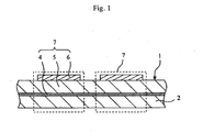
- Fig. 1 is a schematic cross sectional diagram showing a piezoelectric actuator according to the present embodiment. As shown in this figure, this piezoelectric actuator 1 is provided with a number of displacement elements 7 on the surface of a ceramic diaphragm 2. Each displacement element 7 is formed of a common electrode 4, a piezoelectric layer 5 and a drive electrode 6, which are layered in this order, and thus, piezoelectric layer 5 is placed so as to be sandwiched between common electrode 4 and drive electrode 6.
- Common electrode 4 is grounded, and at the same time, a voltage is applied to each drive electrode 6 from the outside. As a result, piezoelectric layer 5 is displaced due to the voltage that is applied across common electrode 4 and drive electrode 6.
- piezoelectric actuator 1 ceramic diaphragm 2 is made of a first piezoelectric ceramic, and piezoelectric layer 5 is made of a second piezoelectric ceramic.
- first piezoelectric ceramic and the second piezoelectric ceramic have approximately the same components, and are made of the materials having different piezoelectric properties. As a result, piezoelectric actuator 1 has excellent durability when driven.
- the above described piezoelectric ceramics mean ceramics exhibiting piezoelectric properties, and compounds in a Bi layer form, materials having a tungsten bronze structure, alkali niobate compounds having a perovskite structure, lead zirconate titanate containing Pb (PZT) and compounds containing lead titanate and having a perovskite structure can be cited as examples. From among these, lead zirconate titanate containing Pb and lead titanate are appropriate from the point of view of enhancing both wettability with and the strength of adhesiveness to electrodes.
- lead titanate and barium titanate are effective in gaining a high binding strength. That is to say, it is preferable for the crystal to contain Pb as an element for forming site A, and contain Zr and/or Ti as an element for forming site B, and in particular, to be of a lead titanate zirconate based compound in order to have a high d constant and to gain a piezoelectric sintered body, which can be displaced to a great degree.
- the same main components are selected for the two in order to make the difference in the coefficient of thermal expansion small, while additives can be changed in order to make the piezoelectric properties different.
- the second piezoelectric ceramic can be made to form a piezoelectric material having many zonal rotational components.
- first piezoelectric ceramic and second piezoelectric ceramic prefferably include Pb, Zr and Ti as the main components.
- PZT for the first piezoelectric ceramic, and to make PZT, which is the main component, contain at least one type of element selected from among Sr, Ba, Ni, Sb, Nb, Zn, Yb and Te in the second piezoelectric ceramic.
- Sr, Ba, Ni, Sb, Nb, Zn, Yb and Te in the second piezoelectric ceramic.
- PZT may be used for the second piezoelectric ceramic, and at least one type of element selected from among Sr, Ba, Ni, Sb, Nb, Zn, Yb and Te may be contained in PZT, which is the main component in the first piezoelectric ceramic.
- an alkaline earth element as an element for forming site A.
- Ba and Sr are preferable as the alkaline earth element from the point of view of gaining a high level of displacement, and when 0.02 mol to 0.08 mol of Ba and 0.02 mol to 0.12 mol of Sr are contained, it is advantageous to gain a great displacement in the case where the main composition is a tetragonal composition.
- the ratio of Zr/Ti in the first piezoelectric ceramic is 0.96 to 0.81, for the ratio of Zr/Ti of the second piezoelectric ceramic to be 1.17 to 0.92, and for the ratio of Zr/Ti of the first piezoelectric ceramic to be smaller than the ratio of Zr/Ti in the second piezoelectric ceramic. As a result, a great binding strength can be gained.
- the lattice constant ratio of c 1 /a 1 in the first piezoelectric ceramic is 1.013 to 1.030, preferably 1.015 to 1.017
- the lattice constant ratio of e 2 /a 2 in the second piezoelectric ceramic is 1.01 to 1.016, preferably 1.011 to 1.a13
- c 1 /a 1 and c 2 /a 2 can be gained, for example, by finding the ratio of the lattice constant of axis a to the lattice constant of axis c in accordance with an X-ray diffraction method (XRD) as described below.
- XRD X-ray diffraction method
- the piezoelectric properties are different between the first and second piezoelectric ceramics, and concretely, it is preferable for the piezoelectric properties of the first piezoelectric ceramic to be not higher than 75%, and particularly, not higher than 7a% of the piezoelectric properties of the second piezoelectric ceramic. Having low piezoelectric properties means having small zonal rotations, providing piezoelectric ceramic with a high binding strength.
- the lower limit value of the above described piezoelectric properties is preferably not lower than 40 %.
- the above described piezoelectric properties mean piezoelectric properties d 31 .
- the piezoelectric properties d 31 can be found, for example, in accordance with a resonance method using an impedance analyzer as described below. Here, when the value of piezoelectric properties d 31 is "-,” this "-" indicates the direction, and the higher the absolute value is, the better the characteristics are.
- Common electrode 4 is fabricated through simultaneous sintering, and therefore, it is made of a silver-palladium alloy which contains not lower than 87 volume % of silver, preferably not lower than 90 volume %, and more preferably not lower than 93 volume %, and it is preferable to control the amount of residual stress, which occurs inside of piezoelectric actuator 1 after sintering, so as to be not higher than 100 MPa. As a result, the effects of reducing compressive stress due to the contraction of electrodes can be expected.
- the average grain diameter of common electrode 4 is 0.1 ⁇ m to 5.0 ⁇ m.
- common electrode 4 In order to increase the strength of adhesiveness, reduce the residual stress and further stabilize piezoelectric properties d 31 , it is preferable for common electrode 4 to include piezoelectric ceramics. These piezoelectric ceramics may be included at the ratio of 10 volume % to 60 volume % when the total amount of the silver-palladium alloy is 100 volume %, preferably 18 volume % to 50 volume %, and more preferably 20 volume % to 30 volume %. As a result, the strength of adhesiveness between common electrode 4 and piezoelectric layer 5 can be increased while the residual stress is reduced.
- the average crystal grain diameter of the above described piezoelectric ceramics is 0.3 ⁇ m to 1.0 ⁇ m in order to make the residual stress uniform. Furthermore, it is preferable for it to be 0.4 ⁇ m to 0.6 ⁇ m in order to suppress the defects. As a result, even in the case where residual stress occurs, the residual stress which occurs in each displacement element 7 is made uniform, and thus has a small variation, and therefore, the effects on piezoelectric properties d 31 are reduced.
- the ratio of orientation of the crystal that forms the second piezoelectric ceramic before polarization is not lower than 50% in the direction of axis a.
- the compressive stress that is applied to displacement elements 7 can be reduced.
- the above described ratio of orientation in axis a is not higher than 75%.
- the above described orientation can be found, for example, by analyzing the crystal structure in accordance with an XRD (X-ray diffraction method).
- a PZT powder is prepared as a powder of the first piezoelectric ceramic, and one type from among the above described PZT based materials is prepared as a powder of the second piezoelectric ceramic. Then, an appropriate organic binder is added to these piezoelectric ceramic powders, which is then formed into a tape form, and a green sheet is fabricated.
- An Ag-Pd paste is applied to and layered on a portion of the fabricated green sheet as a common electrode, and a pressure of 10 MPa to 50 MPa is applied, and after that, is cut into a desired form.
- the binder is removed from this at approximately 400°C, and after that, it is sintered. After sintering, a desired drive electrode is formed on the surface and is polarized, and thus, a piezoelectric actuator 1, which is a layered piezoelectric body, is gained.
- the density before sintering it is preferable for the density before sintering to be not lower than 4.5 g/cm 2 . As a result, it becomes possible to sinter at a low temperature. In the case where the density before sintering is increased, it also becomes easy to suppress the evaporation of Pb.
- a piezoelectric actuator of the present invention is provided with a number of displacement elements on top of one substrate (ceramic diaphragm) as described above, and therefore, can be appropriately used in a liquid discharging device.
- a piezoelectric actuator which is used in a liquid discharging device according to one embodiment of the present invention, is described in detail in reference to the drawings.
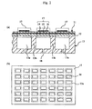
- Fig. 2(a) is a schematic cross sectional diagram showing a liquid discharging device of the present embodiment
- Fig. 2(b) is a plan diagram thereof.
- this liquid discharging device is formed by joining a piezoelectric actuator 11 to a flow path member 13.
- the inside of flow path member 13 is provided with liquid pressurizing chambers 13a and nozzle holes 18, which connect to liquid pressurizing chambers 13a.
- liquid discharging device can be appropriately used as an ink jet print head which is, for example, used in a recording device having an ink jet system.
- a common electrode 14 and a piezoelectric layer 15 are formed on top of a ceramic diaphragm 12 in this order, and furthermore, a number of drive electrodes 16 are formed on the surface of the piezoelectric layer 15 so that a number of displacement elements 17, having a structure where the piezoelectric layer 15 is sandwiched between the common electrode 14 and a drive electrode 16, are formed on the ceramic diaphragm 12.
- This piezoelectric actuator 11 is joined to the flow path member 13.
- the ceramic diaphragm 12 is joined to the flow path member 13 by means of an adhesive or the like so as to close off the top portions of the liquid pressurizing chambers 13a.
- each of the drive electrodes 16 which form the displacement elements 17 is placed on and joined to the portion directly above a liquid pressurizing chamber 13a. Then, the liquid pressurizing chambers 13a are filled with ink.
- a print head can be implemented using an inexpensive IC.
- Such a print head has excellent displacement properties, making possible a high speed discharge with precision, and thus, an appropriate print head for high speed printing can be provided.
- precise high speed printing can be achieved with ease by a printer having, for example, an ink tank for supplying ink to the above described print head and a mechanism for conveying a sheet of paper for recording that makes printing on a sheet of paper for recording possible, in comparison with the prior art.
- a piezoelectric ceramic powder containing lead titanate zirconate (PZT) of a purity of not less than 99% was prepared. Then, using this piezoelectric ceramic powder, ceramic green sheets which are to become first piezoelectric ceramic and second piezoelectric ceramic, as shown in Table 1, were fabricated through sintering. Concretely, butyl methacrylate was added as a water-based binder, ammonium polycarboxylate was added as a dispersing agent, and isopropyl alcohol and pure water was respectively added to the above described piezoelectric ceramic powder as a solvent, and this was mixed so as to gain a slurry. This slurry was applied to a carrier film in accordance with a doctor blade method, and ceramic green sheets in sheet form having a thickness of 30 ⁇ m were fabricated.
- PZT lead titanate zirconate
- the green sheets gained as in the above were used and combined as shown in Table 1, and piezoelectric actuators were fabricated.
- a common electrode paste was printed on the surface of a green sheet (first piezoelectric ceramic) for a ceramic diaphragm so as to have a thickness of 4 ⁇ m, and a common electrode was formed.
- a green sheet for a piezoelectric layer (second piezoelectric ceramic) was layered on a green sheet for a ceramic diaphragm which was laid in such a manner that the side having the common electrode printed on it was facing upwards, and pressure was applied through pressing, and thus, a layered body was gained.
- This layered body was degreased, and after that, held for 4 hours in an atmosphere of not less than 99% oxygen at 980°C so as to be sintered, and thus, a layered body having a piezoelectric layer 5, a ceramic diaphragm 2 and a common electrode 4 as shown in Fig. 1 was fabricated.
- drive electrodes 6 were formed on the surface of the piezoelectric layer 5, in the following manner. That is to say, first, Au paste was applied through screen printing. This was sintered in a normal atmosphere at 600°C to 800°C, so that the drive electrodes 6 were formed.
- the lattice constant ratio c/a and the piezoelectric constant d 31 which indicate the properties of a piezoelectric actuator, were respectively measured in the following manner. The results of measurement are shown in Table 1.
- the lattice constant ratio c/a of each piezoelectric ceramic layer was gained by finding the ratio of the lattice constant in axis a and the lattice constant in axis c through XRD.
- Au was vapor deposited on the front and rear surfaces of the above described layered body (after sintering), and this was processed to a size of 3 mm x 12 mm.
- a direct current voltage of 4 kV/mm was applied for 1 minute via the Au electrodes on the front and rear surfaces, and thus, a polarizing process was carried out.
- d 31 of this sample was found in accordance with a resonance method using an impedance analyzer.
- Each piezoelectric actuator was processed to a size of 8 mm x 8 mm, and thus, test pieces were fabricated.
- each test piece was made to adhere to a metal substrate having an outer form of 10 mm x 10 mm with a hole of 4 mm x 4 mm, and used as a sample for measuring displacement.
- a direct current voltage of 3 kV/mm was applied for 5 minutes across the common electrode and the drive electrodes in the direction of the thickness, and thus, polarization was carried out.
- Second piezoelectric ceramic First piezoelectric ceramic Displacement Ratio of deterioration in durability (%) Material Subcomponent c/a Zr/Ti d 31 Material Subcomponent c/a Zr/Ti d 31 pm/V pm/V nm * 1 PZT Sr ⁇ Ba ⁇ Nb 1.01 1.17 -250 PZT Sr ⁇ Be ⁇ Nb 1.01 1.17 -250 80 10 2 PZT Sr ⁇ Ba ⁇ Nb 1.01 1.17 -220 PZT Sr ⁇ Ba ⁇ Nb 1.013 0.95 -180 78 5 3 PZT Sr ⁇ Ba ⁇ Nb 1.01 1.17 -220 PZT Sr ⁇ Ba ⁇ Nb 1.017 0.88 -130 77 4 4 PZT Sr ⁇ Ba ⁇ Nb 1.012 1 -200 PZT Sr ⁇ Ba ⁇ Nb 1.016 0.92 -150 75 2 5 PZT Sr ⁇ Ba ⁇ Nb 1.012 1 -200 PZT Sr ⁇
- samples No. 2 to 12 of the present invention have a displacement of not less than 53 nm, and the ratio of deterioration in durability after displacement of 50 hours was not higher than 5%.
- sample No. 1 where the first piezoelectric ceramic and the second piezoelectric ceramic are the same, and which is outside the scope of the present invention, had a great ratio of deterioration of not less than 10%.
- samples No. 2 to 12 of the present invention have excellent durability when driven.
Landscapes
- Chemical & Material Sciences (AREA)
- Engineering & Computer Science (AREA)
- Ceramic Engineering (AREA)
- Particle Formation And Scattering Control In Inkjet Printers (AREA)
- General Electrical Machinery Utilizing Piezoelectricity, Electrostriction Or Magnetostriction (AREA)
- Fuel-Injection Apparatus (AREA)
Claims (8)
- Actionneur piézoélectrique (1 ; 11) comprenant :un diaphragme en céramique (2 ; 12) composé d'une première céramique piézoélectrique ; et un certain nombre d'éléments de déplacement (7 ; 17) qui sont fournis sur une surface du diaphragme en céramique,chaque élément de déplacement étant formé d'une couche piézoélectrique (5 ; 15) composée d'une seconde céramique piézoélectrique ainsi que d'une électrode commune (4 ; 14) et d'une électrode de commande (6 ; 16) qui prennent en sandwich cette couche piézoélectrique,caractérisé en ce que
ladite première céramique pièzoélectrique et ladite seconde céramique piézoélectrique sont sensiblement composées des mêmes composants principaux et possèdent des propriétés piézoélectriques différentes. - Actionneur piézoélectrique selon la revendication 1, dans lequel les propriétés piézoélectriques de ladite première céramique piézoélectrique ne dépassent pas 75 % des propriétés piézoélectriques de ladite seconde céramique piézoélectrique.
- Actionneur piézoélectrique selon la revendication 1, dans lequel ladite première céramique piézoélectrique et ladite seconde céramique piézoélectrique comprennent du Pb, du Zr et du Ti en tant que composants principaux.
- Actionneur piézoélectrique selon la revendication 3, dans lequel ladite première céramique piézoélectrique et ladite seconde céramique piézoélectrique contiennent du zirconate titanate de plomb en tant que composant principal, et la seconde céramique piézoélectrique contient au moins un type d'élément choisi dans le groupe constitué par Sr, Ba, Ni, Sb, Nb, Zn, Yb et Te.
- Actionneur piézoélectrique selon la revendication 1, dans lequel le rapport des constantes de réseau c1/a1 de ladite première céramique piézoélectrique est de 1,013 à 1,030, le rapport des constantes de réseau c2/a2 de ladite seconde céramique piézoélectrique est de 1,01 à 1,016 et la valeur de c1/a1 est supérieure à la valeur de c2/a2.
- Actionneur piézoélectrique selon la revendication 1, dans lequel le rapport Zr/Ti dans ladite première céramique piézoélectrique est de 0,96 à 0,81, le rapport Zr/Ti dans ladite seconde céramique piézoélectrique est de 1,17 à 0,92 et le rapport Zr/Ti dans ladite première céramique piézoélectrique est inférieur au rapport Zr/Ti dans ladite seconde céramique piézoélectrique.
- Actionneur piézoélectrique selon la revendication 1, dans lequel le rapport de l'orientation du cristal formant ladite seconde céramique piézoélectrique avant polarisation n'est pas inférieur à 50 % dans la direction de l'axe a.
- Dispositif d'éjection de liquide, comprenant un élément de voie de passage (13) dont l'intérieur est pourvu d'une chambre de pressurisation de liquide (13a) et d'un orifice de buse (18) qui est relié à la chambre de pressurisation de liquide, et d'un actionneur piézoélectrique (11) selon la revendication 1 raccordé à l'élément de voie de passage, dans lequel le liquide avec lequel la chambre de pressurisation de liquide est remplie est mis sous pression au moyen dudit actionneur piézoélectrique, de sorte qu'une goutte de liquide peut être éjectée par ledit orifice de buse.
Applications Claiming Priority (1)
| Application Number | Priority Date | Filing Date | Title |
|---|---|---|---|
| JP2005088390A JP4911907B2 (ja) | 2005-03-25 | 2005-03-25 | 圧電アクチュエータ及び液体吐出装置 |
Publications (3)
| Publication Number | Publication Date |
|---|---|
| EP1705724A2 EP1705724A2 (fr) | 2006-09-27 |
| EP1705724A3 EP1705724A3 (fr) | 2008-08-20 |
| EP1705724B1 true EP1705724B1 (fr) | 2009-08-19 |
Family
ID=36588942
Family Applications (1)
| Application Number | Title | Priority Date | Filing Date |
|---|---|---|---|
| EP20060111701 Ceased EP1705724B1 (fr) | 2005-03-25 | 2006-03-24 | Actionneur piézo-électrique et dispositif d'éjection de liquide |
Country Status (5)
| Country | Link |
|---|---|
| US (1) | US20060214540A1 (fr) |
| EP (1) | EP1705724B1 (fr) |
| JP (1) | JP4911907B2 (fr) |
| CN (1) | CN100559622C (fr) |
| DE (1) | DE602006008516D1 (fr) |
Families Citing this family (8)
| Publication number | Priority date | Publication date | Assignee | Title |
|---|---|---|---|---|
| JP4784611B2 (ja) * | 2008-01-31 | 2011-10-05 | ブラザー工業株式会社 | 圧電アクチュエータの製造方法及び液体移送装置の製造方法 |
| JP5560587B2 (ja) * | 2009-04-30 | 2014-07-30 | ブラザー工業株式会社 | 圧電アクチュエータの製造方法 |
| JP2012206294A (ja) * | 2011-03-29 | 2012-10-25 | Seiko Epson Corp | 液体噴射ヘッドおよび液体噴射装置 |
| US8897469B2 (en) * | 2013-03-12 | 2014-11-25 | Abatech Electronics Co., Ltd. | Slim speaker structure having vibration effect |
| TWI717498B (zh) * | 2016-06-21 | 2021-02-01 | 日商前進材料科技股份有限公司 | 膜構造體及其製造方法 |
| JP7085208B2 (ja) * | 2018-12-11 | 2022-06-16 | 国立研究開発法人産業技術総合研究所 | 圧電体およびそれを用いたmemsデバイス |
| CN113611727B (zh) * | 2021-07-30 | 2023-06-30 | 苏州清越光电科技股份有限公司 | 发声显示屏及其制备方法和工作方法、显示装置 |
| CN116792301A (zh) * | 2023-06-01 | 2023-09-22 | 华为技术有限公司 | 驱动泵、液冷模组、电子设备及振子制备方法 |
Family Cites Families (11)
| Publication number | Priority date | Publication date | Assignee | Title |
|---|---|---|---|---|
| JP3398962B2 (ja) * | 1991-05-09 | 2003-04-21 | 東陶機器株式会社 | 強誘電体磁器組成物 |
| JPH06172027A (ja) * | 1992-12-02 | 1994-06-21 | Toto Ltd | 強誘電体磁器組成物 |
| JP3517876B2 (ja) * | 1998-10-14 | 2004-04-12 | セイコーエプソン株式会社 | 強誘電体薄膜素子の製造方法、インクジェット式記録ヘッド及びインクジェットプリンタ |
| US6523943B1 (en) * | 1999-11-01 | 2003-02-25 | Kansai Research Institute, Inc. | Piezoelectric element, process for producing the piezoelectric element, and head for ink-jet printer using the piezoelectric element |
| JP2003165212A (ja) * | 2001-11-30 | 2003-06-10 | Brother Ind Ltd | インクジェットヘッド |
| JP3903936B2 (ja) * | 2002-03-18 | 2007-04-11 | セイコーエプソン株式会社 | 圧電素子、圧電アクチュエータ、及び、液体噴射ヘッド |
| JP4422973B2 (ja) * | 2002-08-27 | 2010-03-03 | 京セラ株式会社 | 積層圧電体、アクチュエータ及び印刷ヘッド |
| DE10348346A1 (de) * | 2002-10-17 | 2004-05-27 | Kyocera Corp. | Aktuator, Herstellungsverfahren und Druckkopf |
| KR20040070564A (ko) * | 2003-02-04 | 2004-08-11 | 삼성전자주식회사 | 강유전체 커패시터 및 그 제조방법 |
| JP4362045B2 (ja) * | 2003-06-24 | 2009-11-11 | 京セラ株式会社 | 圧電変換装置 |
| JP4307161B2 (ja) * | 2003-06-26 | 2009-08-05 | 京セラ株式会社 | 印刷ヘッド及び電子機器 |
-
2005
- 2005-03-25 JP JP2005088390A patent/JP4911907B2/ja not_active Expired - Fee Related
-
2006
- 2006-03-24 CN CNB2006100680852A patent/CN100559622C/zh not_active Expired - Fee Related
- 2006-03-24 US US11/388,488 patent/US20060214540A1/en not_active Abandoned
- 2006-03-24 DE DE200660008516 patent/DE602006008516D1/de not_active Expired - Lifetime
- 2006-03-24 EP EP20060111701 patent/EP1705724B1/fr not_active Ceased
Also Published As
| Publication number | Publication date |
|---|---|
| CN1838443A (zh) | 2006-09-27 |
| US20060214540A1 (en) | 2006-09-28 |
| JP4911907B2 (ja) | 2012-04-04 |
| EP1705724A3 (fr) | 2008-08-20 |
| EP1705724A2 (fr) | 2006-09-27 |
| JP2006269916A (ja) | 2006-10-05 |
| CN100559622C (zh) | 2009-11-11 |
| DE602006008516D1 (de) | 2009-10-01 |
Similar Documents
| Publication | Publication Date | Title |
|---|---|---|
| KR100651046B1 (ko) | 유전체막 구조체, 유전체막 구조체를 사용하는 압전액추에이터 및 잉크젯 헤드 | |
| JP4422973B2 (ja) | 積層圧電体、アクチュエータ及び印刷ヘッド | |
| US7528530B2 (en) | Piezoelectric substance, piezoelectric substance element, liquid discharge head, liquid discharge device and method for producing piezoelectric substance | |
| EP1965450B1 (fr) | Composition de porcelaine piézoélectrique/électristrictive et élément piézoélectrique/électrostrictif | |
| EP2131409B1 (fr) | Actionneur piézoélectrique stratifié et tête d'éjection de liquide | |
| EP2061099B1 (fr) | Actionneur piézoélectrique en mode cisaillement et tête de délivrance de gouttelettes | |
| EP1705724B1 (fr) | Actionneur piézo-électrique et dispositif d'éjection de liquide | |
| EP2104155B1 (fr) | Procédé de fabrication de composition céramique piézoélectrique/électrostrictive | |
| JP4812244B2 (ja) | 印刷ヘッド | |
| EP2296200A1 (fr) | Tête d'éjection de liquide, appareil d'éjection de liquide et élément piézoélectrique | |
| JP4485140B2 (ja) | 圧電アクチュエータおよびその製造方法 | |
| EP1793431B1 (fr) | Méthode d'inspection d'un actionneur piézoélectrique | |
| JP2006269916A5 (fr) | ||
| JP4977380B2 (ja) | 圧電アクチュエータおよびその駆動方法、並びに印刷ヘッド | |
| EP2287128A1 (fr) | Composition céramique piézoélectrique/électrostrictive | |
| JP5121186B2 (ja) | 圧電体、圧電体素子、液体吐出ヘッド及び液体吐出装置 | |
| JP2005041053A (ja) | 液体吐出装置 | |
| CN101070005B (zh) | 促动器及其制造方法以及打印头 | |
| JP5096659B2 (ja) | 圧電アクチュエータおよび印刷ヘッド | |
| JP2007088445A (ja) | 圧電体、圧電素子、液体吐出ヘッド、液体吐出装置及び圧電体の製造方法 | |
| JP4901165B2 (ja) | 積層圧電体 | |
| JP5144912B2 (ja) | 積層圧電アクチュエータ、および印刷ヘッド | |
| JP2006237077A (ja) | 積層圧電体及び圧電アクチュエータ | |
| JP2007209096A (ja) | 圧電アクチュエータおよび液体噴出装置 |
Legal Events
| Date | Code | Title | Description |
|---|---|---|---|
| PUAI | Public reference made under article 153(3) epc to a published international application that has entered the european phase |
Free format text: ORIGINAL CODE: 0009012 |
|
| AK | Designated contracting states |
Kind code of ref document: A2 Designated state(s): AT BE BG CH CY CZ DE DK EE ES FI FR GB GR HU IE IS IT LI LT LU LV MC NL PL PT RO SE SI SK TR |
|
| AX | Request for extension of the european patent |
Extension state: AL BA HR MK YU |
|
| PUAL | Search report despatched |
Free format text: ORIGINAL CODE: 0009013 |
|
| AK | Designated contracting states |
Kind code of ref document: A3 Designated state(s): AT BE BG CH CY CZ DE DK EE ES FI FR GB GR HU IE IS IT LI LT LU LV MC NL PL PT RO SE SI SK TR |
|
| AX | Request for extension of the european patent |
Extension state: AL BA HR MK YU |
|
| 17P | Request for examination filed |
Effective date: 20081117 |
|
| GRAP | Despatch of communication of intention to grant a patent |
Free format text: ORIGINAL CODE: EPIDOSNIGR1 |
|
| RIN1 | Information on inventor provided before grant (corrected) |
Inventor name: YUU, YOSHIHIRO,C/O KYOCERA CORPORATION, |
|
| AKX | Designation fees paid |
Designated state(s): DE FR GB |
|
| RAP1 | Party data changed (applicant data changed or rights of an application transferred) |
Owner name: KYOCERA CORPORATION |
|
| RAP1 | Party data changed (applicant data changed or rights of an application transferred) |
Owner name: KYOCERA CORPORATION |
|
| GRAS | Grant fee paid |
Free format text: ORIGINAL CODE: EPIDOSNIGR3 |
|
| GRAA | (expected) grant |
Free format text: ORIGINAL CODE: 0009210 |
|
| AK | Designated contracting states |
Kind code of ref document: B1 Designated state(s): DE FR GB |
|
| REG | Reference to a national code |
Ref country code: GB Ref legal event code: FG4D |
|
| REF | Corresponds to: |
Ref document number: 602006008516 Country of ref document: DE Date of ref document: 20091001 Kind code of ref document: P |
|
| RTI2 | Title (correction) |
Free format text: PIEZOELECTRIC ACTUATOR AND LIQUID DISCHARGING DEVICE |
|
| REG | Reference to a national code |
Ref country code: GB Ref legal event code: S117 Free format text: REQUEST FILED; REQUEST FOR CORRECTION UNDER SECTION 117 FILED ON 10 SEPTEMBER 2009 |
|
| PLBE | No opposition filed within time limit |
Free format text: ORIGINAL CODE: 0009261 |
|
| STAA | Information on the status of an ep patent application or granted ep patent |
Free format text: STATUS: NO OPPOSITION FILED WITHIN TIME LIMIT |
|
| 26N | No opposition filed |
Effective date: 20100520 |
|
| REG | Reference to a national code |
Ref country code: FR Ref legal event code: PLFP Year of fee payment: 11 |
|
| REG | Reference to a national code |
Ref country code: DE Ref legal event code: R082 Ref document number: 602006008516 Country of ref document: DE Representative=s name: VIERING, JENTSCHURA & PARTNER MBB PATENT- UND , DE |
|
| REG | Reference to a national code |
Ref country code: FR Ref legal event code: PLFP Year of fee payment: 12 |
|
| REG | Reference to a national code |
Ref country code: FR Ref legal event code: PLFP Year of fee payment: 13 |
|
| PGFP | Annual fee paid to national office [announced via postgrant information from national office to epo] |
Ref country code: DE Payment date: 20200310 Year of fee payment: 15 Ref country code: GB Payment date: 20200311 Year of fee payment: 15 |
|
| PGFP | Annual fee paid to national office [announced via postgrant information from national office to epo] |
Ref country code: FR Payment date: 20200214 Year of fee payment: 15 |
|
| REG | Reference to a national code |
Ref country code: DE Ref legal event code: R119 Ref document number: 602006008516 Country of ref document: DE |
|
| GBPC | Gb: european patent ceased through non-payment of renewal fee |
Effective date: 20210324 |
|
| PG25 | Lapsed in a contracting state [announced via postgrant information from national office to epo] |
Ref country code: DE Free format text: LAPSE BECAUSE OF NON-PAYMENT OF DUE FEES Effective date: 20211001 Ref country code: FR Free format text: LAPSE BECAUSE OF NON-PAYMENT OF DUE FEES Effective date: 20210331 Ref country code: GB Free format text: LAPSE BECAUSE OF NON-PAYMENT OF DUE FEES Effective date: 20210324 |