EP1705732A1 - Lithiumakkumulator - Google Patents
Lithiumakkumulator Download PDFInfo
- Publication number
- EP1705732A1 EP1705732A1 EP06111291A EP06111291A EP1705732A1 EP 1705732 A1 EP1705732 A1 EP 1705732A1 EP 06111291 A EP06111291 A EP 06111291A EP 06111291 A EP06111291 A EP 06111291A EP 1705732 A1 EP1705732 A1 EP 1705732A1
- Authority
- EP
- European Patent Office
- Prior art keywords
- cap plate
- battery
- plate
- cap
- opening
- Prior art date
- Legal status (The legal status is an assumption and is not a legal conclusion. Google has not performed a legal analysis and makes no representation as to the accuracy of the status listed.)
- Granted
Links
Images




Classifications
-
- H—ELECTRICITY
- H01—ELECTRIC ELEMENTS
- H01M—PROCESSES OR MEANS, e.g. BATTERIES, FOR THE DIRECT CONVERSION OF CHEMICAL ENERGY INTO ELECTRICAL ENERGY
- H01M50/00—Constructional details or processes of manufacture of the non-active parts of electrochemical cells other than fuel cells, e.g. hybrid cells
- H01M50/10—Primary casings; Jackets or wrappings
- H01M50/102—Primary casings; Jackets or wrappings characterised by their shape or physical structure
- H01M50/103—Primary casings; Jackets or wrappings characterised by their shape or physical structure prismatic or rectangular
-
- H—ELECTRICITY
- H01—ELECTRIC ELEMENTS
- H01M—PROCESSES OR MEANS, e.g. BATTERIES, FOR THE DIRECT CONVERSION OF CHEMICAL ENERGY INTO ELECTRICAL ENERGY
- H01M10/00—Secondary cells; Manufacture thereof
- H01M10/05—Accumulators with non-aqueous electrolyte
- H01M10/052—Li-accumulators
-
- H—ELECTRICITY
- H01—ELECTRIC ELEMENTS
- H01M—PROCESSES OR MEANS, e.g. BATTERIES, FOR THE DIRECT CONVERSION OF CHEMICAL ENERGY INTO ELECTRICAL ENERGY
- H01M10/00—Secondary cells; Manufacture thereof
- H01M10/05—Accumulators with non-aqueous electrolyte
- H01M10/058—Construction or manufacture
- H01M10/0587—Construction or manufacture of accumulators having only wound construction elements, i.e. wound positive electrodes, wound negative electrodes and wound separators
-
- H—ELECTRICITY
- H01—ELECTRIC ELEMENTS
- H01M—PROCESSES OR MEANS, e.g. BATTERIES, FOR THE DIRECT CONVERSION OF CHEMICAL ENERGY INTO ELECTRICAL ENERGY
- H01M50/00—Constructional details or processes of manufacture of the non-active parts of electrochemical cells other than fuel cells, e.g. hybrid cells
- H01M50/10—Primary casings; Jackets or wrappings
- H01M50/147—Lids or covers
-
- H—ELECTRICITY
- H01—ELECTRIC ELEMENTS
- H01M—PROCESSES OR MEANS, e.g. BATTERIES, FOR THE DIRECT CONVERSION OF CHEMICAL ENERGY INTO ELECTRICAL ENERGY
- H01M50/00—Constructional details or processes of manufacture of the non-active parts of electrochemical cells other than fuel cells, e.g. hybrid cells
- H01M50/10—Primary casings; Jackets or wrappings
- H01M50/147—Lids or covers
- H01M50/148—Lids or covers characterised by their shape
- H01M50/15—Lids or covers characterised by their shape for prismatic or rectangular cells
-
- H—ELECTRICITY
- H01—ELECTRIC ELEMENTS
- H01M—PROCESSES OR MEANS, e.g. BATTERIES, FOR THE DIRECT CONVERSION OF CHEMICAL ENERGY INTO ELECTRICAL ENERGY
- H01M50/00—Constructional details or processes of manufacture of the non-active parts of electrochemical cells other than fuel cells, e.g. hybrid cells
- H01M50/10—Primary casings; Jackets or wrappings
- H01M50/147—Lids or covers
- H01M50/166—Lids or covers characterised by the methods of assembling casings with lids
- H01M50/169—Lids or covers characterised by the methods of assembling casings with lids by welding, brazing or soldering
-
- H—ELECTRICITY
- H01—ELECTRIC ELEMENTS
- H01M—PROCESSES OR MEANS, e.g. BATTERIES, FOR THE DIRECT CONVERSION OF CHEMICAL ENERGY INTO ELECTRICAL ENERGY
- H01M50/00—Constructional details or processes of manufacture of the non-active parts of electrochemical cells other than fuel cells, e.g. hybrid cells
- H01M50/50—Current conducting connections for cells or batteries
- H01M50/572—Means for preventing undesired use or discharge
-
- Y—GENERAL TAGGING OF NEW TECHNOLOGICAL DEVELOPMENTS; GENERAL TAGGING OF CROSS-SECTIONAL TECHNOLOGIES SPANNING OVER SEVERAL SECTIONS OF THE IPC; TECHNICAL SUBJECTS COVERED BY FORMER USPC CROSS-REFERENCE ART COLLECTIONS [XRACs] AND DIGESTS
- Y02—TECHNOLOGIES OR APPLICATIONS FOR MITIGATION OR ADAPTATION AGAINST CLIMATE CHANGE
- Y02E—REDUCTION OF GREENHOUSE GAS [GHG] EMISSIONS, RELATED TO ENERGY GENERATION, TRANSMISSION OR DISTRIBUTION
- Y02E60/00—Enabling technologies; Technologies with a potential or indirect contribution to GHG emissions mitigation
- Y02E60/10—Energy storage using batteries
-
- Y—GENERAL TAGGING OF NEW TECHNOLOGICAL DEVELOPMENTS; GENERAL TAGGING OF CROSS-SECTIONAL TECHNOLOGIES SPANNING OVER SEVERAL SECTIONS OF THE IPC; TECHNICAL SUBJECTS COVERED BY FORMER USPC CROSS-REFERENCE ART COLLECTIONS [XRACs] AND DIGESTS
- Y02—TECHNOLOGIES OR APPLICATIONS FOR MITIGATION OR ADAPTATION AGAINST CLIMATE CHANGE
- Y02P—CLIMATE CHANGE MITIGATION TECHNOLOGIES IN THE PRODUCTION OR PROCESSING OF GOODS
- Y02P70/00—Climate change mitigation technologies in the production process for final industrial or consumer products
- Y02P70/50—Manufacturing or production processes characterised by the final manufactured product
Definitions
- the present invention relates to a lithium secondary battery. More particularly, the present invention relates to a battery configured to accommodate externally-applied pressure in a safe manner, wherein a cap portion can be bent in a predetermined direction when the battery is subjected to a transversely-applied pressure, in order to increase a margin of safety against potential short circuits.
- FIG. 1 illustrates an exploded perspective view of a conventional battery.
- a conventional battery may include an electrode assembly 112 having a positive electrode plate 113, a negative electrode plate 115 and a separator 114.
- the battery may further include a housing to enclose the electrode assembly 112, the housing including a can 110 for receiving the electrode assembly 112 and an electrolyte, and a cap assembly 120 for tightly sealing an upper opening 110a of the can 110.
- the electrode assembly 112 may have the separator 114 wound between the positive electrode plate 113 and the negative electrode plate 115.
- a positive electrode tap 116 may be coupled to the positive electrode plate 113 and may protrude from an upper end of the electrode assembly 112.
- a negative electrode tap 117 may be coupled to the negative electrode plate 115 and may protrude from the upper end of the electrode assembly 112.
- the positive electrode tap 116 and the negative electrode tap 117 may be spaced apart by a predetermined distance and may be electrically insulated from each other.
- the positive electrode tap 116 and the negative electrode tap 117 may be made of metal, e.g., nickel.
- the can 110 may be made of, e.g., aluminum or an alloy thereof, and may be formed by, e.g., a deep drawing method.
- the can 110 may have a substantially flat bottom surface.
- the cap assembly 120 may include a cap plate 140, an insulation plate 150, a terminal plate 160 and an electrode terminal 130.
- the cap assembly 120 may be associated with a separate insulation case 170, and may then be coupled to the upper opening 110a of the can 110 so as to tightly seal the can 110.
- the cap plate 140 may be made from, e.g., a metal plate, and may have a size and shape corresponding to those of the upper opening 110a of the can 110.
- the cap plate 140 may have a hole 141 formed therethrough at a center portion thereof.
- the hole 141 may have a predetermined size for receiving the electrode terminal 130.
- the cap plate 140 may also have an electrolyte injection hole 142 formed therein in a suitable location, e.g., offset to one side.
- the electrolyte injection hole 142 may have a predetermined size and may be sealed by a sealing means 143.
- the electrolyte injection hole 142 provides for electrolyte to be injected through the cap assembly 120 after the cap assembly 120 is coupled to the upper opening 110a of the can 110. After injection of the electrolyte, the injection hole 142 may be sealed.
- the insulation plate 150 may be made from an insulation material and may be attached to the lower surface of the cap plate 140.
- the insulation plate 150 may have a hole 151 formed therethrough corresponding to the hole 141, such that the electrode terminal 130 may pass through the hole 151.
- the insulation plate 150 may also have a receiving recess 152 formed in a lower surface thereof, in order to receive the terminal plate 160.
- the terminal plate 160 may be made of a metal, e.g., a nickel alloy, and may be attached to the lower surface of the insulation plate 150.
- the terminal plate 160 may have a hole 161 formed therethrough corresponding to the hole 141, such that the electrode terminal 130 may pass through the holes 141, 161.
- the electrode terminal 130 may make contact with the terminal plate 160, e.g., along a contact region at the periphery of the hole 161.
- the electrode terminal 130 may pass through the holes 141, 151 and 161 and may be electrically connected with the terminal plate 160 while being electrically insulated from the cap plate 140 by a gasket 146 and the insulation plate 150.
- the negative electrode tap 117 which is coupled to the negative electrode plate 115, may be welded to a side of the terminal plate 160.
- the positive electrode tap 116 which is coupled to the positive electrode plate 113, may be welded to a side of the cap plate 140 opposite to the negative electrode tap 117.
- the negative electrode tap 117 may be welded to the cap plate 140, and the positive electrode tap 116 may be welded to the terminal plate 160.
- Suitable welding methods may include, e.g., resistance welding, laser welding, etc. Of these, resistance welding may be particularly suitable.
- the electrode terminal 130 may have the gasket 146 mounted thereon.
- the gasket 146 may be made of any suitable insulating material including, e.g., the material used for the insulation plate 150.
- the gasket 146 may be any suitable form, including, e.g., tubular, annular, flat with a hole defined therethrough, etc.
- the electrode terminal 130 may be inserted, along with the gasket 146, into the hole 141, such that the electrode terminal 130 is insulated from the cap plate 140.
- the electrode terminal 130 may be connected to the negative electrode tap 117, and thus to the negative electrode plate 115, or it may be connected to the positive electrode tap 116, and thus to the positive electrode plate 113, so as to operate as a negative or positive electrode terminal.
- the battery illustrated in FIG. 1 may be a conventional lithium secondary battery.
- Battery designs for the latest portable devices may take advantage of the lithium secondary battery's high energy density to provide small form factor batteries, e.g., thin batteries having an elongated, rectangular shape.
- such designs may have weak battery housings, i.e., the battery may not be able to withstand impact or externally applied pressure.
- the electrode assembly contained in the battery housing may be deformed due to deformation of the can. This may, in turn, result in internal defects such as an internal electric short circuit between the electrode plates. Such defects may have serious results, including fires and explosions of the battery.
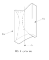
- FIG. 2 illustrates a generalized perspective view of a compressed conventional battery housing.
- FIG. 2 illustrates a conventional battery housing that has been compressed by a force Fa applied in a transverse direction, i.e., applied to opposing sides of the can 110 in a direction normal to the longitudinal axis b.
- Fa a force applied in a transverse direction
- FIGS. 1 and 2 when the battery is deformed by this transversely-applied force Fa, as is done during compression safety tests, the substantially flat bottom surface of the can 110 may deform inward and upward.
- the substantially flat top surface of the cap assembly 120 may deform inward and downward.
- the deformation or caving-in of the can 110 bottom may apply pressure to the electrode assembly 112 contained in the battery housing. In particular, it may force the electrode assembly 112 upward and against the cap assembly 120. This may result in the upper portion of the electrode assembly 112 coming into contact with various elements of the cap assembly 120, possibly causing an internal electric short circuit between the electrode plates and subsequent fire or explosion of the battery.
- a lithium secondary battery which substantially overcomes one or more of the problems due to the limitations and disadvantages of the related art.
- a lithium secondary battery configured to accommodate externally-applied pressure in a safe manner when the battery is subjected to a transversely-applied pressure.
- a lithium secondary battery comprising:
- a battery including an electrode assembly having electrode plates, a can defining a space receiving the electrode assembly, and a cap plate covering the space, wherein the cap plate is configured to deform away from the space when predetermined sides of the can are deformed toward the space.
- the deformation region is a protuberance formed upward at a center portion of the cap plate, the protuberance including a stepped portion.
- the stepped portion may have a side surface inclined at an angle with respect to a major surface of the cap plate.
- the stepped portion may have a side surface normal to a major surface of the cap plate.
- the stepped portion may have a curved side surface.
- the stepped portion may have a height equal to at least 50% of a thickness of the cap plate.
- the protuberance may have a long dimension with a length of about 20% to about 70% of the cap plate.
- the cap plate may include two stepped portions extending away from the opening of the can, the stepped portions defining a center region of the cap plate, a hole may be defined through the cap plate in the center region, and the electrode assembly may further include an electrode terminal disposed through the hole and electrically coupled to an electrode plate.
- the cap plate may have a recess defined in a surface that faces the opening of the can, and end regions of the cap plate may be coplanar with a center region of the cap plate.
- the recess may form a loop in the surface, the loop enclosing the center region.
- the loop may enclose a substantially rectangular region.
- At least two recesses may be defined in the surface, the recesses extending laterally across a width of the cap plate.
- an inner surface of the cap plate faces the opening and the deformation region includes at least one concave feature at the inner surface of the cap plate.
- the opening and the cap plate may be monolithically formed.
- the concave feature may be defined by at least one stepped portion, the stepped portion extending away from the space.
- the concave feature may be defined by two stepped portions extending away from the opening and laterally across a width of the cap plate, the two stepped portions defining two end regions and a central region, and the central region may be offset from the two end regions, such that an inner surface of the central region is not coplanar with inner surfaces of the two end regions.
- the concave feature may be a groove formed in the inner surface of the cap plate.
- the groove may be continuously formed in a loop.
- a battery housing for a battery electrode assembly including a body, the body defining a space to contain the battery electrode assembly, and a cap plate defining an upper wall of the space, wherein an inner surface of the cap plate faces the space and includes at least one concave feature.
- the body and the cap plate may be monolithically formed.
- the concave feature may be defined by at least one stepped portion, the stepped portion extending away from the space.
- a battery housing for housing an electrode assembly, including a can having an opening for receiving the electrode assembly, and a unit for covering the opening without short circuiting the electrode assembly if predetermined sides of the can are deformed inwardly.
- the unit for covering may be configured to deform outward, away from the electrode assembly, if the predetermined sides of the can are deformed inwardly.
- a battery according to the present invention includes a cap plate configured to prevent internal electric short circuits.
- the cap plate may have a stepped portion formed upward, and a corresponding concave underside, at a central region of the cap plate, such that transverse pressure applied to the battery causes deformation to the cap plate to occur in an upward direction, thereby preventing the upper portion of the electrode assembly contained in the battery housing from being pressed against the cap plate and avoiding internal electric short circuits between the electrode plates.
- FIG. 3 illustrates an exploded perspective view of a battery and battery housing according to the present invention.
- the battery according to the present invention may include an electrode assembly 312 having a positive electrode plate 313, a negative electrode plate 315 and a separator 314.
- the battery housing may include a can 310 containing the electrode assembly 312 and an electrolyte, and may include a cap assembly 320 for tightly sealing an upper opening 310a of the can 310.
- the electrode assembly 312 may have the separator 314 wound between the positive electrode plate 313 and the negative electrode plate 315.
- a positive electrode tap 316 may be coupled to the positive electrode plate 313 and may protrude from the upper portion of the electrode assembly 312.
- a negative electrode tap 317 may be coupled to the negative electrode plate 315 and may protrude from the upper portion of the electrode assembly 312.
- the positive electrode tap 316 and the negative electrode tap 317 may be spaced apart and electrically may be insulated from each other.
- the positive electrode tap 316 and the negative electrode tap 317 may be formed from a metal, e.g., nickel metal.
- the cap assembly 320 may include a cap plate 340, an insulation plate 350, a terminal plate 360 and an electrode terminal 330.
- the cap assembly 320 may be associated with a separate insulation case 370, and may then be coupled to the upper opening 310a so as to tightly seal the can 310.
- the cap plate 340 may have a hole 342 provided therein for the injection of electrolyte.
- the cap plate 340 may be formed of a metal and may have a thickness of about 0.8 mm. The cap plate 340 will be described in greater detail below.
- the insulation plate 350 may be made from an insulation material and may be attached to a lower surface of the cap plate 340.
- the insulation plate 350 may have a hole 351 formed therethrough corresponding to a hole 341.
- the electrode terminal 330 may extend through the holes 341, 351.
- the insulation plate 350 may also have a recess 352 formed in a lower surface thereof, in order to receive the terminal plate 360.
- the terminal plate 360 may be made of a metal, e.g., a nickel alloy, and may be attached to the lower surface of the insulation plate 350.
- the terminal plate 360 may have a hole 361 formed therethrough corresponding to the hole 341, such that the electrode terminal 330 may pass through the holes 341, 361.
- the electrode terminal 330 may make contact with the terminal plate 360, e.g., along a contact region at the periphery of the hole 361. Accordingly, the electrode terminal 330 may pass through the holes 341, 351 and 361, and may be electrically connected with terminal plate 360, while being electrically insulated from the cap plate 340 by a gasket 346 and the insulation plate 350.
- the negative electrode tap 317 which is coupled to the negative electrode plate 315, may be welded to a side of the terminal plate 360.
- the positive electrode tap 316 which is coupled to the positive electrode plate 313, may be welded to a side of the cap plate 340 opposite to the negative electrode tap 317.
- the negative electrode tap 317 may be welded to the cap plate 340, and the positive electrode tap 316 may be welded to the terminal plate 360.
- Suitable welding methods may include, e.g., resistance welding, laser welding, etc.
- the electrode terminal 330 may have the gasket 346 mounted thereon.
- the gasket 346 may be made of any suitable insulating material including, e.g., the material used for the insulation plate 350.
- the gasket 346 may be any suitable form, including, e.g., tubular, annular, flat with a hole defined therethrough, etc.
- the electrode terminal 330 may be inserted, along with the gasket 346, into the hole 341, such that the electrode terminal 330 is insulated from the cap plate 340.
- the electrode terminal 330 may be connected to the negative electrode tap 317, and thus to the negative electrode plate 315, or it may be connected to the positive electrode tap 316, and thus to the positive electrode plate 313, so as to operate as a negative or positive electrode terminal.
- the cap assembly 320 of FIGS. 4A-4B may have the cap plate 340 substituted by cap plates 540, 640, 740 and 840.
- FIG. 4A illustrates a plan view of the cap plate 340 for the battery and battery housing, according to a first embodiment of the present invention
- FIG. 4B illustrates a sectional view of the cap plate 340 of FIG. 4A, taken along line A-A in FIG. 4A
- the battery and battery housing according to the first embodiment of the present invention may include the cap plate 340.
- the cap plate 340 may be, e.g., a metal plate, and may have a shape and dimensions corresponding to the upper opening 310a of the can 310 illustrated in FIG. 3, in order to be installed therein.
- the cap plate 340 may have the hole 341 formed therethrough, at a center portion thereof, the hole 341 having a predetermined size, to accommodate the insertion of the electrode terminal 330.
- the gasket 346 may be mounted around the periphery of the electrode terminal 330 and inserted, along with the electrode terminal 330, into the hole 341, in order to insulate the electrode terminal 330 from the cap plate 340.
- the cap plate 340 may also have the hole 342 formed at a side thereof for the injection of electrolyte.
- the cap plate 340 may have stepped portions 410 formed therein, the stepped portions 410 configured to extend away from the bulk of the battery housing when the cap assembly 320, which includes the cap plate 340, is assembled to the can 310. That is, the stepped portions 410 may extend upward, away from the body of the battery, and correspondingly define a concave underside of the cap plate 340. In other words, the cap plate 340 has a protuberance being realized as the stepped portions 410.
- the protuberance defines a deformation region, that means if one are more predetermined sides of the can 310 are deformed inwardly by pressure then the region, respectively the protuberance will deform away from the opening (outwardly).
- the stepped portion 410 may be inclined at an angle with respect to a longitudinal axis b of the battery. This may allow the cap plate 340 to bend outward easily, away from the body of the battery, when the lithium secondary battery is subjected to the transversely-applied force Fa.
- the stepped portion 410 may have a height h greater than about 50% of the thickness t of the cap plate 340.
- the upper surface of a center region 445 of the cap plate 340 may be offset from the upper surface of the peripheral regions of the cap plate 340 by the height h, i.e. offset away from the body of the battery by the height h.
- the height h may be determined in consideration of the final assembly of the cap plate 340 to the other elements of the cap assembly 320.
- the stepped portion 410 may have a height h of about 0.1 mm to about 0.5 mm in some implementations.
- the cap assembly 320 may have little or no effect when the can 310 is subjected to the transverse force Fa, and the cap assembly 320 may not deform away from the body of the battery. If the height h of the step portion 410 too great, e.g., larger than about 0.5 mm, the cap assembly may be effective at bending away from the body of the battery in response to the transverse force Fa, but the cap assembly 320 may have an overall height that is too great, such that the battery does not satisfy the size requirements of the particular application. However, where size requirements are not an issue, the height h of the stepped portion 410 need not be limited.
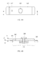
- FIG. 5A illustrates a plan view of a cap plate for the battery and battery housing, according to a second embodiment of the present invention
- FIG. 5B illustrates a sectional view of the cap plate of FIG. 5A, taken along line B-B in FIG. 5A
- the cap plate 540 may include a stepped portion 510 protruding upward, wherein the side surfaces are vertically formed.
- the stepped portion 510 is configured to cause the cap plate 540 to bend outward in response to the transverse force Fa, so as to reduce the chances of an internal electric short circuit, in similar fashion to that described above in connection with the cap plate 340.
- the vertically formed side surfaces of the stepped portion 510 may cause the cap plate 540 to bend outward to a lesser extent than the cap plate 340.
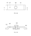
- FIG. 6A illustrates a plan view of a cap plate for the battery and battery housing, according to a third embodiment of the present invention
- FIG. 6B illustrates a sectional view of the cap plate of FIG. 6A, taken along line C-C in FIG. 6A
- the cap plate 640 may include a stepped portion 610 protruding upward, wherein the side surfaces are curved.
- the stepped portion 610 is configured to cause the cap plate 640 to bend outward in response to the transverse force Fa, in similar fashion to that described above in connection with the cap plate 340.
- FIG. 7A illustrates a plan view of a cap plate for the battery and battery housing, according to a fourth embodiment of the present invention
- FIG. 7B illustrates a sectional view of the cap plate of FIG. 7A, taken along line D-D in FIG. 7A
- the cap plate 740 may include stepped portions 710 protruding upward, wherein a center region 745 of the cap plate 740 is defined by the stepped portions 710.
- the stepped portions may protrude upward in any suitable form, including, e.g., at an angle, perpendicular to the major plane of the cap plate 740, or in a rounded shape, as described above in connection with FIGS. 4A-6B.
- the center region 745 may constitute a predetermined portion of the cap plate 740.
- the length l 1 of the center region 745, as defined by two stepped portions 710, may be about 20% to about 70% of the overall length of the cap plate 740.
- the center region 745 may be too long.
- the end regions of the cap plate 740, outside the center region 745, may be so short that welding in the end regions becomes impractical.
- the center region 745 may have a detrimental effect on the ability of the cap plate 740 to deform outwardly in response to the transverse force Fa. Specifically, the magnitude of the outward deformation of the cap plate 740 may be insufficient to provide the desired margin of safety for the electrode assembly 312, i.e., the electrode assembly 312 may get short circuited when the battery housing is deformed.
- the center region 745 may be too short. In particular, it may make the mounting of a terminal plate 360 to the insulation plate 350 unstable when the cap assembly 320 is put together.
- the stepped portions 710 also define end regions 746 of the cap plate 740.
- Each end region 746 may have a length l 2 of about 1 mm to about 10 mm, as defined between the stepped portion 710 and the end of the cap plate 740.
- the cap plate 740 has a thickness of 0.8 mm, and the end region 746 has a length l 2 that is greater than about 1 mm, in order to provide a stable portion whereby the cap plate 740 is welded to the upper opening 310a of the can 310.
- the end region 746 may also have a length l 2 that is less than or equal to about 10 mm, in order to allow enough room in the center region 745 for the insulation plate 350 and the terminal plate 360, which are mounted below the cap plate 740.
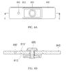
- FIG. 8A illustrates a plan view of a cap plate for the battery and battery housing, according to a fifth embodiment of the present invention
- FIG. 8B illustrates a sectional view of the cap plate of FIG. 8A, taken along line E-E in FIG. 8A
- the cap plate 840 may include a feature 810, wherein the feature 810 is a concave recess formed on the underside of the cap plate 840.
- the feature 810 is configured to cause the cap plate 840 to bend outward in response to the transverse force Fa, in similar fashion to that described above in connection with the cap plate 340.
- the upper surface of the cap plate 840 may be substantially planar, while the opposite surface, i.e., the inner surface when the cap plate 840 is installed in the can 310, has the feature 810 formed therein.
- the feature 810 may be, e.g., a groove.
- the center region of the cap plate is displaced or vertically offset from the end regions of the cap plate in the embodiments described above in connection with FIGS. 4A-7A, in the fifth embodiment the center region of the cap plate 840 may be substantially coplanar with the end regions of the cap plate 840.
- the feature 810 may be formed as a continuous, substantially rectangular feature, i.e., a substantially rectangular loop, that defines a center region inside the feature 810, as illustrated in FIG. 8A.
- the feature 810 may surround the electrode terminal 830.
- discontinuous features 810 may be formed, e.g., a pair of linear features (not shown) may be formed across the width of the cap plate 840, i.e., so as to be transverse to the line E-E in FIG. 8A.
- Still other implementations are possible, including continuous features defining, e.g., a rectangle having equal length sides (a square), an ellipse, etc.
- the feature 810 may be formed by any suitable operation including, e.g., etching or stamping.
- the feature 810 is formed by a stamping operation.
- the stamping operation may generate a corresponding convex protuberance 810' extending above the substantially planar surface of the cap plate 840, away from the battery. That is, in the implementation illustrated in FIGS. 8A and 8B, a stamping operation may simultaneously form the feature 810 on the underside of the cap plate 840 and the corresponding protuberance 810' on the top side of the cap plate 840.
- the protuberance 810' may be a relatively narrow elevated feature formed in a substantially rectangular loop shape. Apart from this protuberance 810', the upper surface of the cap plate 840 may be planar.
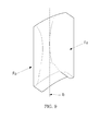
- FIG. 9 illustrates a generalized perspective view of a compressed battery housing according to the present invention.
- the substantially flat bottom surface of the can 110 may deform inward and upward.
- the cap assembly may be bent upward and outward. As a result, no force is applied to the upper portion of the electrode assembly contained in the battery housing, so that an internal electric short circuit does not occur in the electrode assembly.
- Exemplary embodiments of the present invention have been disclosed herein, and although specific terms are employed, they are used and are to be interpreted in a generic and descriptive sense only and not for purpose of limitation.
- the battery housing is described as having the cap plate separately provided and mounted to the battery housing, it will be appreciated that the cap plate according to the present invention may be monolithically formed with the battery housing, e.g., by a deep drawing process, and another portion of the housing, e.g., a separately formed bottom plate, may be separately provided in order to allow installation of the electrode assembly.
- the present invention while described above in the context of a prismatic or rectangular battery, may similarly be applied to cylindrical batteries, e.g., cylindrical lithium secondary batteries.
Landscapes
- Chemical & Material Sciences (AREA)
- Chemical Kinetics & Catalysis (AREA)
- Electrochemistry (AREA)
- General Chemical & Material Sciences (AREA)
- Engineering & Computer Science (AREA)
- Manufacturing & Machinery (AREA)
- Sealing Battery Cases Or Jackets (AREA)
- Secondary Cells (AREA)
- Connection Of Batteries Or Terminals (AREA)
Applications Claiming Priority (1)
| Application Number | Priority Date | Filing Date | Title |
|---|---|---|---|
| KR1020050024668A KR20060102751A (ko) | 2005-03-24 | 2005-03-24 | 리튬 이차전지 |
Publications (2)
| Publication Number | Publication Date |
|---|---|
| EP1705732A1 true EP1705732A1 (de) | 2006-09-27 |
| EP1705732B1 EP1705732B1 (de) | 2015-06-17 |
Family
ID=36591330
Family Applications (1)
| Application Number | Title | Priority Date | Filing Date |
|---|---|---|---|
| EP06111291.8A Ceased EP1705732B1 (de) | 2005-03-24 | 2006-03-17 | Lithiumakkumulator |
Country Status (5)
| Country | Link |
|---|---|
| US (2) | US8497033B2 (de) |
| EP (1) | EP1705732B1 (de) |
| JP (1) | JP4537334B2 (de) |
| KR (1) | KR20060102751A (de) |
| CN (1) | CN1838462B (de) |
Cited By (3)
| Publication number | Priority date | Publication date | Assignee | Title |
|---|---|---|---|---|
| EP2487735A3 (de) * | 2011-02-10 | 2013-06-05 | Samsung SDI Co., Ltd. | Sekundärbatterie |
| CN111566846A (zh) * | 2017-12-13 | 2020-08-21 | 三星Sdi株式会社 | 二次电池 |
| CN119208858A (zh) * | 2024-11-29 | 2024-12-27 | 深圳海辰储能科技有限公司 | 储能装置及用电设备 |
Families Citing this family (27)
| Publication number | Priority date | Publication date | Assignee | Title |
|---|---|---|---|---|
| USD556130S1 (en) * | 2004-06-22 | 2007-11-27 | Mitsumi Electric Co., Ltd. | Battery protection circuit module |
| KR20060102751A (ko) * | 2005-03-24 | 2006-09-28 | 삼성에스디아이 주식회사 | 리튬 이차전지 |
| JP2008112638A (ja) * | 2006-10-30 | 2008-05-15 | Sanyo Electric Co Ltd | 電池の製造方法 |
| KR100882912B1 (ko) * | 2007-10-15 | 2009-02-10 | 삼성에스디아이 주식회사 | 캡 조립체, 이를 구비하는 이차 전지, 상기 캡 조립체의제조방법 및 상기 이차전지의 제조방법 |
| KR100973309B1 (ko) * | 2007-12-13 | 2010-07-30 | 삼성에스디아이 주식회사 | 이차 전지용 절연 케이스 및 이를 구비하는 이차 전지 |
| KR101073193B1 (ko) * | 2009-09-28 | 2011-10-12 | 삼성에스디아이 주식회사 | 이차전지 |
| KR101122900B1 (ko) * | 2009-11-17 | 2012-03-21 | 삼성에스디아이 주식회사 | 이차전지용 케이스 및 이를 이용한 리튬 이차전지 |
| KR101233459B1 (ko) * | 2011-02-22 | 2013-02-14 | 삼성에스디아이 주식회사 | 이차 전지 |
| US9419252B2 (en) * | 2011-07-28 | 2016-08-16 | Samsung Sdi Co., Ltd. | Rechargeable battery |
| US20130029211A1 (en) * | 2011-07-28 | 2013-01-31 | Samsung Sdi Co., Ltd. | Rechargeable Battery |
| JP6237864B2 (ja) * | 2011-11-29 | 2017-11-29 | 株式会社Gsユアサ | 蓄電素子 |
| JP6115084B2 (ja) * | 2011-11-29 | 2017-04-19 | 株式会社Gsユアサ | 蓄電素子 |
| JP6048080B2 (ja) * | 2011-11-29 | 2016-12-21 | 株式会社Gsユアサ | 蓄電素子 |
| JP5858235B2 (ja) * | 2012-04-16 | 2016-02-10 | 三菱自動車工業株式会社 | 電池 |
| KR101947835B1 (ko) * | 2013-01-03 | 2019-02-13 | 삼성에스디아이 주식회사 | 이차전지 |
| KR101693294B1 (ko) * | 2013-01-21 | 2017-01-05 | 삼성에스디아이 주식회사 | 이차 전지 |
| KR101724006B1 (ko) * | 2013-09-13 | 2017-04-06 | 삼성에스디아이 주식회사 | 이차 전지 |
| KR102283782B1 (ko) * | 2014-11-26 | 2021-07-30 | 삼성에스디아이 주식회사 | 이차전지 |
| KR101545734B1 (ko) * | 2014-12-30 | 2015-08-19 | 한국단자공업 주식회사 | 차량용 배터리블록 |
| KR102344362B1 (ko) * | 2015-03-11 | 2021-12-28 | 삼성에스디아이 주식회사 | 배터리 모듈 |
| JP6996505B2 (ja) * | 2016-06-29 | 2022-01-17 | 三洋電機株式会社 | 二次電池 |
| KR102611656B1 (ko) * | 2016-08-30 | 2023-12-08 | 삼성에스디아이 주식회사 | 이차 전지 |
| CN110190221B (zh) * | 2019-05-14 | 2020-09-04 | 宁德时代新能源科技股份有限公司 | 电池模块和电池包 |
| CN216120451U (zh) * | 2021-07-20 | 2022-03-22 | 宁德时代新能源科技股份有限公司 | 端盖组件、电池单体、电池和使用电池的装置 |
| CN117242639A (zh) * | 2022-01-05 | 2023-12-15 | 宁德时代新能源科技股份有限公司 | 电池单体及其制造设备和制造方法、电池以及用电装置 |
| CN216872125U (zh) * | 2022-02-21 | 2022-07-01 | 宁德时代新能源科技股份有限公司 | 电池单体、电池和用电设备 |
| JP7774592B2 (ja) * | 2023-03-22 | 2025-11-21 | プライムプラネットエナジー&ソリューションズ株式会社 | 電池セル |
Citations (5)
| Publication number | Priority date | Publication date | Assignee | Title |
|---|---|---|---|---|
| JPH08162084A (ja) * | 1994-12-06 | 1996-06-21 | Matsushita Electric Ind Co Ltd | 薄型電池用防爆封口板 |
| EP0862229A1 (de) * | 1995-11-13 | 1998-09-02 | Konno kogyosho Co., Ltd. | Brechbares sicherungsventil für metallischen behälter |
| US6159631A (en) * | 1998-08-27 | 2000-12-12 | Polystor Corporation | Overcharge safety vents on prismatic cells |
| EP1132983A1 (de) * | 2000-03-09 | 2001-09-12 | Sanyo Electric Co., Ltd. | Batterie-Sicherheitsventil und Herstellverfahren dafür |
| US20050069760A1 (en) * | 2003-09-30 | 2005-03-31 | Yoshiki Somatomo | Sealed rectangular battery |
Family Cites Families (11)
| Publication number | Priority date | Publication date | Assignee | Title |
|---|---|---|---|---|
| US4347293A (en) | 1980-04-29 | 1982-08-31 | Gte Products Corporation | Electrochemical cell |
| US5567539A (en) | 1994-05-23 | 1996-10-22 | Fuji Photo Film Co., Ltd. | Non-aqueous secondary cell |
| JP3555240B2 (ja) | 1995-05-12 | 2004-08-18 | ソニー株式会社 | 密閉型電池 |
| US6001504A (en) * | 1998-03-11 | 1999-12-14 | Duracell Inc. | Prismatic battery housing |
| JP2001126679A (ja) * | 1999-10-29 | 2001-05-11 | Nec Mobile Energy Kk | 密閉型電池 |
| JP2002329484A (ja) * | 2001-04-27 | 2002-11-15 | Yuasa Corp | 密閉形電池 |
| KR100463188B1 (ko) | 2002-06-24 | 2004-12-23 | 삼성에스디아이 주식회사 | 리튬 이온 전지용 전해질 및 이를 포함하는 리튬 이온 전지 |
| JP2004039445A (ja) * | 2002-07-03 | 2004-02-05 | Toyota Motor Corp | 電池ケース |
| JP3898153B2 (ja) * | 2003-05-28 | 2007-03-28 | Necトーキン株式会社 | 密閉型二次電池 |
| KR100508947B1 (ko) | 2003-06-18 | 2005-08-17 | 삼성에스디아이 주식회사 | 이차 전지 및 이의 밀봉 방법 |
| KR20060102751A (ko) * | 2005-03-24 | 2006-09-28 | 삼성에스디아이 주식회사 | 리튬 이차전지 |
-
2005
- 2005-03-24 KR KR1020050024668A patent/KR20060102751A/ko not_active Ceased
-
2006
- 2006-03-13 US US11/373,209 patent/US8497033B2/en not_active Expired - Fee Related
- 2006-03-13 JP JP2006067894A patent/JP4537334B2/ja not_active Expired - Fee Related
- 2006-03-17 EP EP06111291.8A patent/EP1705732B1/de not_active Ceased
- 2006-03-24 CN CN2006100714609A patent/CN1838462B/zh not_active Expired - Fee Related
-
2013
- 2013-07-25 US US13/950,761 patent/US8771867B2/en not_active Expired - Fee Related
Patent Citations (5)
| Publication number | Priority date | Publication date | Assignee | Title |
|---|---|---|---|---|
| JPH08162084A (ja) * | 1994-12-06 | 1996-06-21 | Matsushita Electric Ind Co Ltd | 薄型電池用防爆封口板 |
| EP0862229A1 (de) * | 1995-11-13 | 1998-09-02 | Konno kogyosho Co., Ltd. | Brechbares sicherungsventil für metallischen behälter |
| US6159631A (en) * | 1998-08-27 | 2000-12-12 | Polystor Corporation | Overcharge safety vents on prismatic cells |
| EP1132983A1 (de) * | 2000-03-09 | 2001-09-12 | Sanyo Electric Co., Ltd. | Batterie-Sicherheitsventil und Herstellverfahren dafür |
| US20050069760A1 (en) * | 2003-09-30 | 2005-03-31 | Yoshiki Somatomo | Sealed rectangular battery |
Non-Patent Citations (1)
| Title |
|---|
| PATENT ABSTRACTS OF JAPAN vol. 1996, no. 10 31 October 1996 (1996-10-31) * |
Cited By (6)
| Publication number | Priority date | Publication date | Assignee | Title |
|---|---|---|---|---|
| EP2487735A3 (de) * | 2011-02-10 | 2013-06-05 | Samsung SDI Co., Ltd. | Sekundärbatterie |
| US8785037B2 (en) | 2011-02-10 | 2014-07-22 | Samsung Sdi Co., Ltd. | Secondary battery with stepped cap plate |
| CN111566846A (zh) * | 2017-12-13 | 2020-08-21 | 三星Sdi株式会社 | 二次电池 |
| CN111566846B (zh) * | 2017-12-13 | 2022-10-21 | 三星Sdi株式会社 | 二次电池 |
| US11664523B2 (en) | 2017-12-13 | 2023-05-30 | Samsung Sdi Co., Ltd. | Secondary battery |
| CN119208858A (zh) * | 2024-11-29 | 2024-12-27 | 深圳海辰储能科技有限公司 | 储能装置及用电设备 |
Also Published As
| Publication number | Publication date |
|---|---|
| CN1838462A (zh) | 2006-09-27 |
| US8497033B2 (en) | 2013-07-30 |
| JP4537334B2 (ja) | 2010-09-01 |
| CN1838462B (zh) | 2010-12-01 |
| US20130309557A1 (en) | 2013-11-21 |
| US20060216592A1 (en) | 2006-09-28 |
| KR20060102751A (ko) | 2006-09-28 |
| US8771867B2 (en) | 2014-07-08 |
| JP2006269423A (ja) | 2006-10-05 |
| EP1705732B1 (de) | 2015-06-17 |
Similar Documents
| Publication | Publication Date | Title |
|---|---|---|
| US8771867B2 (en) | Battery and battery housing | |
| US20230178788A1 (en) | Cap assembly for secondary battery, secondary battery and battery module | |
| US7862928B2 (en) | Can for a battery and battery using the same | |
| EP2362466B1 (de) | Wiederaufladbare Batterie mit Kurzschluss-Aktivierungselement | |
| EP2273587B1 (de) | Wiederaufladbare Batterie | |
| US9318732B2 (en) | Lithium rechargeable battery | |
| CN102064333B (zh) | 电池 | |
| US9118071B2 (en) | Rechargeable battery | |
| US9028993B2 (en) | Secondary battery | |
| JP5021900B2 (ja) | 密閉型電池 | |
| KR100709873B1 (ko) | 이차전지 | |
| KR100515356B1 (ko) | 이차 전지 및 이의 안전변 제조 방법 | |
| US20120208075A1 (en) | Secondary Battery | |
| KR20160015778A (ko) | 내진동 특성이 향상된 원통형 전지 | |
| US20060216578A1 (en) | Lithium secondary battery | |
| US12567657B2 (en) | Connecting lead and battery | |
| CN100423351C (zh) | 锂可充电电池 | |
| KR19980702192A (ko) | 박형전지 | |
| KR100624952B1 (ko) | 리튬 이차전지용 캔 및 이를 이용한 리튬 이차전지 | |
| KR200228355Y1 (ko) | 각형전지의캡조립체 | |
| KR100614355B1 (ko) | 리튬이온 이차전지 | |
| KR101285961B1 (ko) | 리튬 이차전지 | |
| KR20080057629A (ko) | 전극조립체와 그를 이용한 원통형 이차전지 |
Legal Events
| Date | Code | Title | Description |
|---|---|---|---|
| PUAI | Public reference made under article 153(3) epc to a published international application that has entered the european phase |
Free format text: ORIGINAL CODE: 0009012 |
|
| 17P | Request for examination filed |
Effective date: 20060317 |
|
| AK | Designated contracting states |
Kind code of ref document: A1 Designated state(s): AT BE BG CH CY CZ DE DK EE ES FI FR GB GR HU IE IS IT LI LT LU LV MC NL PL PT RO SE SI SK TR |
|
| AX | Request for extension of the european patent |
Extension state: AL BA HR MK YU |
|
| AKX | Designation fees paid |
Designated state(s): DE FR GB |
|
| GRAP | Despatch of communication of intention to grant a patent |
Free format text: ORIGINAL CODE: EPIDOSNIGR1 |
|
| INTG | Intention to grant announced |
Effective date: 20150121 |
|
| GRAS | Grant fee paid |
Free format text: ORIGINAL CODE: EPIDOSNIGR3 |
|
| GRAA | (expected) grant |
Free format text: ORIGINAL CODE: 0009210 |
|
| AK | Designated contracting states |
Kind code of ref document: B1 Designated state(s): DE FR GB |
|
| REG | Reference to a national code |
Ref country code: GB Ref legal event code: FG4D |
|
| REG | Reference to a national code |
Ref country code: DE Ref legal event code: R096 Ref document number: 602006045688 Country of ref document: DE |
|
| REG | Reference to a national code |
Ref country code: FR Ref legal event code: PLFP Year of fee payment: 11 |
|
| REG | Reference to a national code |
Ref country code: DE Ref legal event code: R097 Ref document number: 602006045688 Country of ref document: DE |
|
| PLBE | No opposition filed within time limit |
Free format text: ORIGINAL CODE: 0009261 |
|
| STAA | Information on the status of an ep patent application or granted ep patent |
Free format text: STATUS: NO OPPOSITION FILED WITHIN TIME LIMIT |
|
| 26N | No opposition filed |
Effective date: 20160318 |
|
| REG | Reference to a national code |
Ref country code: FR Ref legal event code: PLFP Year of fee payment: 12 |
|
| REG | Reference to a national code |
Ref country code: FR Ref legal event code: PLFP Year of fee payment: 13 |
|
| PGFP | Annual fee paid to national office [announced via postgrant information from national office to epo] |
Ref country code: DE Payment date: 20200303 Year of fee payment: 15 Ref country code: GB Payment date: 20200304 Year of fee payment: 15 |
|
| PGFP | Annual fee paid to national office [announced via postgrant information from national office to epo] |
Ref country code: FR Payment date: 20200227 Year of fee payment: 15 |
|
| REG | Reference to a national code |
Ref country code: DE Ref legal event code: R079 Ref document number: 602006045688 Country of ref document: DE Free format text: PREVIOUS MAIN CLASS: H01M0002040000 Ipc: H01M0050147000 |
|
| REG | Reference to a national code |
Ref country code: DE Ref legal event code: R119 Ref document number: 602006045688 Country of ref document: DE |
|
| GBPC | Gb: european patent ceased through non-payment of renewal fee |
Effective date: 20210317 |
|
| PG25 | Lapsed in a contracting state [announced via postgrant information from national office to epo] |
Ref country code: GB Free format text: LAPSE BECAUSE OF NON-PAYMENT OF DUE FEES Effective date: 20210317 Ref country code: FR Free format text: LAPSE BECAUSE OF NON-PAYMENT OF DUE FEES Effective date: 20210331 Ref country code: DE Free format text: LAPSE BECAUSE OF NON-PAYMENT OF DUE FEES Effective date: 20211001 |