EP1705907A1 - Frontprojektions-mehrfachprojektions-display - Google Patents
Frontprojektions-mehrfachprojektions-display Download PDFInfo
- Publication number
- EP1705907A1 EP1705907A1 EP04801622A EP04801622A EP1705907A1 EP 1705907 A1 EP1705907 A1 EP 1705907A1 EP 04801622 A EP04801622 A EP 04801622A EP 04801622 A EP04801622 A EP 04801622A EP 1705907 A1 EP1705907 A1 EP 1705907A1
- Authority
- EP
- European Patent Office
- Prior art keywords
- unit
- type multi
- projection display
- projection type
- front projection
- Prior art date
- Legal status (The legal status is an assumption and is not a legal conclusion. Google has not performed a legal analysis and makes no representation as to the accuracy of the status listed.)
- Withdrawn
Links
- 230000003287 optical effect Effects 0.000 claims description 33
- 239000003086 colorant Substances 0.000 claims description 10
- 238000011156 evaluation Methods 0.000 claims 1
- 238000000034 method Methods 0.000 abstract description 7
- 230000008569 process Effects 0.000 abstract description 6
- 238000010586 diagram Methods 0.000 description 49
- 230000008901 benefit Effects 0.000 description 40
- 239000004973 liquid crystal related substance Substances 0.000 description 40
- 238000010276 construction Methods 0.000 description 16
- 230000006866 deterioration Effects 0.000 description 6
- 230000000694 effects Effects 0.000 description 6
- 230000008859 change Effects 0.000 description 4
- 230000003203 everyday effect Effects 0.000 description 4
- 230000004044 response Effects 0.000 description 4
- 238000002834 transmittance Methods 0.000 description 4
- 230000007547 defect Effects 0.000 description 3
- 230000003247 decreasing effect Effects 0.000 description 2
- 230000002349 favourable effect Effects 0.000 description 2
- 238000009434 installation Methods 0.000 description 2
- 238000009877 rendering Methods 0.000 description 2
- 230000004907 flux Effects 0.000 description 1
- 238000005286 illumination Methods 0.000 description 1
- 230000006872 improvement Effects 0.000 description 1
- QSHDDOUJBYECFT-UHFFFAOYSA-N mercury Chemical compound [Hg] QSHDDOUJBYECFT-UHFFFAOYSA-N 0.000 description 1
- 229910052753 mercury Inorganic materials 0.000 description 1
- 229910001507 metal halide Inorganic materials 0.000 description 1
- 150000005309 metal halides Chemical class 0.000 description 1
- 238000012544 monitoring process Methods 0.000 description 1
- 230000009467 reduction Effects 0.000 description 1
- 239000004065 semiconductor Substances 0.000 description 1
Images













Classifications
-
- G—PHYSICS
- G03—PHOTOGRAPHY; CINEMATOGRAPHY; ANALOGOUS TECHNIQUES USING WAVES OTHER THAN OPTICAL WAVES; ELECTROGRAPHY; HOLOGRAPHY
- G03B—APPARATUS OR ARRANGEMENTS FOR TAKING PHOTOGRAPHS OR FOR PROJECTING OR VIEWING THEM; APPARATUS OR ARRANGEMENTS EMPLOYING ANALOGOUS TECHNIQUES USING WAVES OTHER THAN OPTICAL WAVES; ACCESSORIES THEREFOR
- G03B21/00—Projectors or projection-type viewers; Accessories therefor
- G03B21/14—Details
- G03B21/26—Projecting separately subsidiary matter simultaneously with main image
-
- H—ELECTRICITY
- H04—ELECTRIC COMMUNICATION TECHNIQUE
- H04N—PICTORIAL COMMUNICATION, e.g. TELEVISION
- H04N9/00—Details of colour television systems
- H04N9/12—Picture reproducers
- H04N9/31—Projection devices for colour picture display, e.g. using electronic spatial light modulators [ESLM]
- H04N9/3141—Constructional details thereof
- H04N9/3147—Multi-projection systems
-
- G—PHYSICS
- G03—PHOTOGRAPHY; CINEMATOGRAPHY; ANALOGOUS TECHNIQUES USING WAVES OTHER THAN OPTICAL WAVES; ELECTROGRAPHY; HOLOGRAPHY
- G03B—APPARATUS OR ARRANGEMENTS FOR TAKING PHOTOGRAPHS OR FOR PROJECTING OR VIEWING THEM; APPARATUS OR ARRANGEMENTS EMPLOYING ANALOGOUS TECHNIQUES USING WAVES OTHER THAN OPTICAL WAVES; ACCESSORIES THEREFOR
- G03B21/00—Projectors or projection-type viewers; Accessories therefor
-
- G—PHYSICS
- G03—PHOTOGRAPHY; CINEMATOGRAPHY; ANALOGOUS TECHNIQUES USING WAVES OTHER THAN OPTICAL WAVES; ELECTROGRAPHY; HOLOGRAPHY
- G03B—APPARATUS OR ARRANGEMENTS FOR TAKING PHOTOGRAPHS OR FOR PROJECTING OR VIEWING THEM; APPARATUS OR ARRANGEMENTS EMPLOYING ANALOGOUS TECHNIQUES USING WAVES OTHER THAN OPTICAL WAVES; ACCESSORIES THEREFOR
- G03B21/00—Projectors or projection-type viewers; Accessories therefor
- G03B21/14—Details
-
- H—ELECTRICITY
- H04—ELECTRIC COMMUNICATION TECHNIQUE
- H04N—PICTORIAL COMMUNICATION, e.g. TELEVISION
- H04N5/00—Details of television systems
- H04N5/74—Projection arrangements for image reproduction, e.g. using eidophor
-
- H—ELECTRICITY
- H04—ELECTRIC COMMUNICATION TECHNIQUE
- H04N—PICTORIAL COMMUNICATION, e.g. TELEVISION
- H04N9/00—Details of colour television systems
- H04N9/12—Picture reproducers
- H04N9/31—Projection devices for colour picture display, e.g. using electronic spatial light modulators [ESLM]
- H04N9/3191—Testing thereof
- H04N9/3194—Testing thereof including sensor feedback
Definitions
- the present invention relates to a front projection type multi-projection display.
- a front projection type multi-projection display in which a plurality of projector units (projection optical unit) are arranged in a horizontal direction and in a vertical direction and projection images from the plurality of projector units are projected onto a screen in a magnified scale to display one large screen image is known (for example, see Patent Documents 1 to 9).
- Such a multi-projection display can display images with high definition and high brightness, as compared to other conventional projectors.
- the multi-projection display will have wide commercial applications in future in business fields, such as cinemas, art galleries, museums, seminar halls, assembly halls, mini-theaters, public institutes, and companies or for domestic uses, such as an amusement and a home theater.
- Patent Document 1 Japanese Unexamined Patent Application Publication No. 8-82854
- Patent Document 2 Japanese Unexamined Patent Application Publication No. 8-94974
- Patent Document 3 Japanese Unexamined Patent Application Publication No. 2001-339672
- Patent Document 6 Japanese Unexamined Patent Application Publication No. 2001-251651
- Patent Document 7 Japanese Unexamined Patent Application Publication No. 6-178327
- Patent Document 8 Japanese Unexamined Patent Application Publication No. 9-211386
- the front projection type multi-projection display In the front projection type multi-projection display, generally, due to unevenness in characteristic in the light source or the electro-optical modulating device, it is the present situation that a brightness characteristic or a color characteristic for every projector unit is different. For this reason, in the front projection type multi-projection display, a voltage to be applied to the electro-optical modulating device for every projector unit is adjusted such that the difference of the brightness characteristics or the color characteristics is absorbed. As a result, in the front projection type multi-projection display, by performing the adjustment, the gradation source is needed to be used in the electro-optical modulating device, which results in problems in that the number of effective gradations inherent in the front projection type multi-projection display is lowered or the dynamic range becomes narrow.
- the front projection type multi-projection display of the present invention by controlling the amount of light emitted from the solid-state light source for every projector unit, it is possible to absorb the difference of the brightness characteristics or the color characteristics. For this reason, according to the front projection type multi-projection display of the present invention, since there is no need to use the gradation source in the electro-optical modulating device, there is no case in which the number of effective gradations inherent in the front projection type multi-projection display is lowered or the dynamic range becomes narrow.
- the front projection type multi-projection display of the invention unlike a case in which the high pressure mercury lamp or the metal halide lamp is used as the light source, even though the output of the solid-state light source changes high or low irrespective of the height of voltage, the color temperature is not almost changed. Thus, there is no deterioration of the image quality.
- the solid-state light source control unit preferably has a function of dynamically controlling the amount of light emitted from the solid-state light source.
- the solid-state light source control unit is allowed to dynamically control the amount of light emitted from the solid-state light source, for each projector unit, when an image in which a bright screen and a dark screen exist in one screen is displayed, it is possible for the front projection type multi-projection display to exhibit the expression ability exceeding the number of effective gradation or the dynamic range inherent in the front projection type multi-projection display. In addition, it is possible to perform high image quality display.
- the solid-state light source control unit preferably has a function of controlling a voltage to be supplied to the solid-state light source for every projector unit or for every electro-optical modulating device.
- the solid-state light source control unit preferably has a function of controlling an emitting period of the solid-state light source for every projector unit or for every electro-optical modulating device.
- the electro-optical modulating device is a liquid crystal device which writes one unit screen information twice or more
- the solid-state light source control unit has a function of allowing the solid-state light source to emit during one frame outside at least the first writing period of the liquid crystal device.
- the liquid crystal device is a hold type display device, unlike a case of a CRT of an impulse type display device, there is a problem in that a smooth moving picture display is not obtained due to a so-called tailing phenomenon (as regards the tailing phenomenon, see 'image quality of moving picture display in a hold type display' ( IEICE Technical Report, EID99-10, pages 55 to 60 (1999-06 )).
- the front projection type multi-projection display by performing writing twice or more to one unit screen information, it is possible to make a flicker inconspicuous.
- a liquid crystal device of a so-called n-time speed driving here, n is a natural number of 2 or more
- the solid-state light source is allowed to emit outside at least the first writing period of the liquid crystal device.
- the solid-state light source is allowed to emit during one frame outside the first writing period at which liquid crystal molecules do not yet sufficiently response.
- the electro-optical modulating device be a liquid crystal device which writes an image sequentially for every screen region
- the solid-state light source control unit has a function of allowing the solid-state light source to emit during one frame outside the image writing periods of the liquid crystal device.
- a liquid crystal device which is capable of making a flicker inconspicuous by writing sequentially images for every screen region is used, and the solid-state light source is allowed to emit outside the image writing periods of the liquid crystal device.
- the solid-state light source is allowed to emit outside the image writing periods of the liquid crystal device.
- the solid-state light source is allowed to emit outside the image writing periods.
- the solid-state light source is allowed to emit outside the image writing periods.
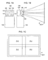
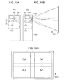
- Fig. 1 is a diagram showing a construction of a front projection type multi-projection display according to a first embodiment.
- Fig. 1A is a front view thereof
- Fig. 1B is a cross-sectional view as viewed from a side
- Fig. 1C is a view showing a projection image projected onto the screen.
- Fig. 2 is a diagram showing a construction of a projector unit in the front projection type multi-projection display according to the first embodiment.
- Figs. 3 to 5 are block diagrams showing an outline of the front projection type multi-projection display according to the first embodiment.
- the front projection type multi-projection display 100 is a front projection type multi-projection display in which images projected from 4 projector units 130 disposed in a housing 102 are projected onto a screen SCR as a projection plane.
- the front projection type multi-projection display 100 is provided on a stand 104, as shown in Figs. 1A and 1B.
- the respective projector units 130 comprises LED light sources 132R, 132G, and 132B as a solid-state light source, three liquid crystal devices 134R, 134G, and 134B as an electro-optical modulating device, a cross dichroic prism 136 and a projection lens 138.
- Illumination light components from the LED light sources 132R, 132G, and 132B are modulated by the liquid crystal devices 134R, 134G, and 134B based on unit image information A 1 to A n (see Fig. 3) or adjusting unit image information B 1 to B n (see Fig. 4) and are projected by the projection lens 138.
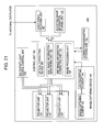
- the front projection type multi-projection display 100 comprises a control unit 110 having a unit image information generating unit 120, a unit image information correcting unit 150, an image processing unit 146, and an optical correcting device 154, four projector units 130, 30, 130, 130 an image-capturing device 140, a video signal receiving unit 160, an adjusting image information storing unit 122, and a correction parameter storing unit 152, as shown in Figs. 3 to 5.
- the unit image information generating unit 120 has a function of generating a plurality of unit image information A 1 to A n based on original image information A (see Fig. 3) and a function of generating the adjusting unit image information B 1 to B n based on the adjusting image information B (see Fig. 4).
- the image-capturing device 140 comprises an image-capturing element 142 for capturing a predetermined region of an adjusting image projected onto the screen SCR and an AD converting element 144 for converting an analog signal from the image-capturing element 142 into a digital signal.
- the image processing unit 146 has a function of comparing a result obtained by performing an image processing on the result captured by the image-capturing device 140 to the adjusting image information B to output the comparison result to the unit image information correcting unit 150.
- the unit image information correcting unit 150 has a function of correcting unit image information based on the result captured by the image-capturing device 140 such that a boundary between unit images projected by adjacent projector units among the plurality of projector units 130 is not noticeable on the screen SCR.
- corrected unit image information A 1* to A n* are outputted to the respective projector units 130 (see Fig. 5).
- the correction parameter storing unit 152 has a function of storing correction parameters determined when the unit image information correcting unit 150 corrects the unit image information.
- the adjusting image information storing unit 122 has a function of storing information regarding to adjusting images which are objects to be captured by the image-capturing device 140.
- the image-capturing device 140 is provided inside (at an inner position immediate to a front of) a housing 102 of the front projection type multi-projection display 100 and has an image-capturing element 142 for capturing a projection image.
- the front projection type multi-projection display 100 of the first embodiment it is possible to easily achieve the precise positional information of the image-capturing element 142 with respect to the projector units 130, and as a result it is possible to analyze more accurately the projection image, compared to the conventional art.
- the front projection type multi-projection display 100 of the first embodiment it is easy to put the control circuit for processing a result captured by the image-capturing device 140 in the housing 102 and as a result it is easy to move and install the front projection type multi-projection display 100.
- the LED light sources 132R, 132G, and 132B which can acquire a stable emitting state immediately after being turned on is used as light sources of the projector units 130, it is possible to drastically shorten the time required until the image-capturing device 140 captures the predetermined region of the adjusting image to be projected onto the screen SCR for every projector unit 130. As a result, the adjustment time for matching the projection images from the respective projector units 130 is drastically shortened, which greatly improves the convenience of the display device.
- the LED light sources 132R, 132G, and 132B can be easily set to a turned-on state or a turned-off state, a shutter used in the above mentioned Patent Document 3 is no longer needed. Also, since the LED light sources 132R, 132G, and 132B can acquire the stable emitting state immediately after being turned on, it is possible to begin capturing at once. Further, the time needed to operate the shutter can be shortened, and thus the adjustment time can be further shortened.
- the front projection type multi-projection display 100 of the first embodiment since the LED light sources 132R, 132G, and 132B are used as the solid-state light source, in addition to having a stable emitting state, the front projection type multi-projection display also has a sufficient brightness and color-rendering property.
- the image-capturing device 140 changes the capturing range S. Therefore, it is possible to capture images with a wide capturing range and a high magnification and to capture efficiently the projection image in various capturing modes.
- the image-capturing device 140 further have a zoom-function and an auto-focus function. Therefore, since it is possible to change the capturing range S or the magnifications with the zoom-function, the degree of freedom or flexibility of capturing is improved. Further, since the focus is automatically adjusted with the auto-focus function, the convenience is greatly improved.
- the image-capturing device 140 can capture the entire screen SCR, it is possible to improve the color balance and brightness balance in the entire screen.
- the unit image information correcting unit 150 preferably corrects unit image information based on the result of capturing the adjusting unit images which are projected by each of the projector units 130.
- the unit image information correcting unit 150 may correct unit image information based on the result of capturing a general image. However, in the present embodiment, by correcting unit image information based on the result of capturing the adjusting unit images, it is possible to correct more accurately and rapidly.
- the adjusting image information may be inputted in the front projection type multi-projection display 100 (by means of a DVD or the like) and the unit image information generating unit 120 may generate the adjusting unit image information using the adjusting image information. Further, every when the adjustment operation is performed, the adjusting unit image information may be directly inputted in the front projection type multi-projection display 100.
- the unit image information correcting unit 150 has a function of correcting the shapes, the positions and/or the inclinations of the unit images to be projected by the respective projector units 130. For this reason, the shapes, the positions and/or the inclinations between the projection images from the respective projector units 130 become proper, and thus it is possible to highly match the projection images from the respective projector units 130.
- the unit image information correcting unit 150 has another function of correcting the brightness and/or colors of the unit images to be projected by the respective projector units 130. For this reason, the brightness and/or colors between the projection images from the respective projector units 130 become proper, and thus it is possible to highly match the projection images from the respective projector units 130.
- the unit image information correcting unit 150 has a function of correcting the brightness and/or colors for every pixel in a plurality of projector units 130, 130, 130, 130. Accordingly, since the matching between the projection images from the respective projector units 130 is improved, it is possible to project the image true to the original image information to the screen SCR.
- the unit image information correcting unit 150 has another function of correcting the brightness and/or colors of the unit image for every pixel in the respective projector units 130 by comparing all of the adjusting images formed by a plurality of adjusting unit images projected by the plurality of projector units 130, 130, 130, 130 with the original adjusting image.
- the unit image information correcting unit 150 corrects the unit image information by using a correction parameter determined based on the captured result. Therefore, after determining the correction parameter based on the captured result, it is possible to correct easily the unit image information by using the determined correction parameter.
- the front projection type multi-projection display 100 further comprises the correction parameter storing unit 152 for storing the correction parameter. Therefore, it is possible to reduce the necessary storage capacity, compared with the case of storing the captured results and to reduce the calculation amount when correcting the unit image information.
- the front projection type multi-projection display 100 further comprises an automatic correction parameter acquiring device (not shown) for acquiring automatically the correction parameter by capturing the adjusting image in certain circumstances. For example, when the re-determination (re-acquisition) of the correction parameter is required (for example, when three months have lapsed after re-acquisition), the automatic correction parameter acquiring device automatically operates to re-acquire the correction parameter. Further, the automatic correction parameter acquiring device automatically operates at a regularly scheduled time everyday (for example, at 4 a.m.) to re-acquire the correction parameter. Accordingly, it is possible to maintain uniformly the image quality without bothering user to improve the convenience.
- an automatic correction parameter acquiring device for acquiring automatically the correction parameter by capturing the adjusting image in certain circumstances. For example, when the re-determination (re-acquisition) of the correction parameter is required (for example, when three months have lapsed after re-acquisition), the automatic correction parameter acquiring device automatically operates to re-acquire the correction parameter. Further, the automatic
- the property of the LED light source 132R, 132G, and 132B or the liquid crystal device 134R, 134G, and 134B varies with response to the variation over time, it is possible to obtain automatically the correction parameter corresponding to the variation of property. Therefore, the deterioration of the image quality due to the variation over time can be prevented.
- the front projection type multi-projection display 100 further has an optical correcting device 154 for correcting the position and/or orientation of optical elements in the front projection type multi-projection display 100. Therefore, after correcting the position and/or orientation of the optical elements, the uniform image quality can be obtained. Since this correction is optically performed, the image quality does not deteriorate by performing the adjustment operation.
- the position and/or orientation of the optical elements is optically corrected, the capturing operation is performed again by using the image-capturing device 140, and then the correction parameters are preferably determined based on the captured result.
- the correction parameters are preferably determined based on the captured result.
- the front projection type multi-projection display 100 further has an automatic optical element correcting device (not shown) for correcting automatically the position and/or orientation of the optical elements by capturing an adjusting image in certain circumstances. Therefore, when correction of the optical elements is required (for example, when three months have lapsed after re-acquisition), or at a regularly scheduled time everyday (for example, at 4 a.m.), the automatic optical element correcting device automatically operates to correct the position and/or orientation of the optical elements. Accordingly, it is possible to maintain uniformly the image quality without bothering user to improve the convenience.
- an automatic optical element correcting device for correcting automatically the position and/or orientation of the optical elements by capturing an adjusting image in certain circumstances. Therefore, when correction of the optical elements is required (for example, when three months have lapsed after re-acquisition), or at a regularly scheduled time everyday (for example, at 4 a.m.), the automatic optical element correcting device automatically operates to correct the position and/or orientation of the optical elements. Accordingly, it is possible to maintain uniformly the image
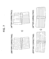
- Figs. 6 to 12 are diagrams showing advantages of the front projection type multi-projection display according to the first embodiment.
- the front projection type multi-projection display 100 may correct the shapes, the positions and/or the inclinations between the projection images from the respective projector units 130 will be described. Further, how the brightness and/or colors between the projection images from the respective projector units 130 may be corrected will be described.
- the unit image information generating unit 120 if original image information A is inputted from the video signal receiving unit 160 to the unit image information generating unit 120, the unit image information generating unit 120 generates unit image information A 1 to A n based on original image information A.
- the respective projector units 130 project the unit images corresponding to unit image information A 1 to A n onto the screen SCR. Therefore, on the screen SCR, the projection images according to the respective unit images from the respective projector units 130 are projected.
- the front projection type multi-projection display 100 is in a state before correcting, the distorted projection images (I a0 , I b0 , I c0 , I d0 ) as shown in Fig. 6(i) are projected.
- the first adjustment operation will be described.
- the unit image information generating unit 120 if adjusting image information B from the adjusting image information storing unit 122 is inputted to the unit image information generating unit 120, the unit image information generating unit 120 generates adjusting unit image information B 1 to B n based on adjusting image information B.
- the respective projector units 130 project the unit images corresponding to adjusting unit image information B 1 to B n onto the screen SCR.
- the front projection type multi-projection display 100 is in a state before correcting, similarly to the above description, since the front projection type multi-projection display 100 is in a state before correcting, the distorted projection images (I a0 , I b0 , I c0 , I d0 ) as shown in Fig. 6(i) are projected, similar to the above.
- the optical correcting device 154 optically corrects the position and/or orientation of the housing of the respective projector units 130 based on the captured result.
- the position and/or orientation of the projection lens 138 of each of the projector units 130 may be optically corrected.
- the respective projector units 130 project the unit images corresponding to adjusting unit image information B 1 to B n onto the screen SCR.
- the position and/or orientation of the housing of the respective projector units 130 are being corrected based on the previous captured result in the front projection type multi-projection display 100.
- the projection images (I a1 , I b1 , I c1 , I d1 ) having reduced distortion are projected.
- the unit image information correcting unit 150 determines the correction parameters to be used when unit image information is corrected. Subsequently, the determined correction parameters are stored in the correction parameter storing unit 152, and then, based on the correction parameters, a plurality of unit image information are generated from original image information.
- the unit image information generating unit 120 generates unit image information based on original image information A.
- unit image information is corrected by the correction parameters, thus, unit image information A 1* to A n* are generated. Therefore, the respective projector units 130 project the unit images corresponding to unit image information A 1* to A n* onto the screen SCR.
- the projection images (I a2 , I b2 , I c2 , I d2 ) from the respective projector units 130 are aligned precisely.
- the correction may be performed such that reference lines of the adjusting images in adjacent two projector units comply with each other, or the operation may be executed such that the reference line of the adjusting image in one projector unit 130 is captured.
- the LED light sources 132R, 132G, and 132B which can acquire the stable emitting state immediately after being turned on are used as the light source of the respective projector units 130, it is possible to drastically shorten the time required for the above-mentioned adjustment operation.
- the third adjustment operation will be described.
- an adjustment of an overlapped region in adjacent two projector units temporaryly, referred to as PJU a and PJU b ) will be described.
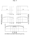
- a weight function in the overlapped region is add to a pixel value of unit image information such that the projection images (I a2 , I b2 ) from the adjacent projector units PJU a and PJU b are connected smoothly to each other.
- the weight function as shown in Fig. 10, a weight function taking ⁇ correction into consideration is used.
- the projection images from the adjacent projector units PJU a and PJU b are smoothly connected to each other.
- the projection images from the adjacent two projector units PJU a and PJU b are favorably synthesized and smoothly connected to each other.
- the unit images are generated such that they are smoothly connected to each other on the screen SCR (Fig. 12C).
- the projection images from the adjacent two projector units PJU a and PJU b are favorably synthesized and smoothly connected to each other.
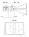
- Fig. 13 is a diagram showing a construction of a front projection type multi-projection display according to a second embodiment.
- Fig. 14 is a diagram illustrating advantages of the front projection type multi-projection display according to the second embodiment.
- the front projection type multi-projection display 200 is constructed such that an optical axis of a projection light flux from each of the projector units 130 is orthogonal to the screen surface of the screen SCR, as shown in Fig. 13.
- the image-capturing device 140 is provided inside (at an inner position immediate to a front of) the housing 102, it is possible to obtain the same advantages as those of the front projection type multi-projection display 100 according to the first embodiment.
- Fig. 15 is a block diagram showing an outline of a front projection type multi-projection display according to the third embodiment.
- Fig. 16 is a diagram illustrating advantages of the front projection type multi-projection display according to the third embodiment.
- Fig. 16A is a diagram showing advantages in the case in which the unit image has trapezoidal distortion
- Fig. 16B is a diagram showing advantages in the case in which the unit image does not have trapezoidal distortion.
- the front projection type multi-projection display 300 according to the third embodiment has a construction of a control unit different from the front projection type multi-projection display 100 according to the first embodiment. That is, in the front projection type multi-projection display 300 according to the third embodiment, the control unit 310 has a construction excluding the optical correcting device 154 from the construction of the control unit 110 in the front projection type multi-projection display 100 according to the first embodiment.
- the front projection type multi-projection display 300 according to the third embodiment has an image-capturing device 140 which is provided inside (at an inner position immediate to a front of) a housing of the front projection type multi-projection display, it is possible to obtain the same advantages as those of the front projection type multi-projection display 100 according to the first embodiment.
- the front projection type multi-projection display 300 according to the third embodiment can correct the unit images without using the optical correcting device. Thus, it is possible to simplify the structure. Further, it has an advantage in that it is possible to attain cost reduction and reliability improvement.
- the front projection type multi-projection display 300 can be suitably used as a stationary front projection type multi-projection display in which the positional relation to the screen is fixed.
- the unit image information is corrected only by the working of the unit image information correcting unit 150, without using the optical correcting device.
- the adjustment method will be described.
- the unit image information generating unit 120 generates unit image information A 1 to A n based on the original image information A.
- the respective projector units 130 project the unit images corresponding to unit image information A 1 to A n onto the screen SCR. Therefore, on the screen SCR, the projection images corresponding to the respective unit images from the respective projector units 130 are projected.
- the distorted projection images I a0 , I b0 , I c0 , I d0 ) as shown in Figs. 16A (i) and 16B(i) are projected.
- the first adjustment operation will be described.
- the unit image information generating unit 120 generates adjusting unit image information B 1 to B n (not shown) based on adjusting image information B.
- the respective projector units 130 project the unit images corresponding to adjusting unit image information B 1 to B n onto the screen SCR.
- the distorted projection images I a0 , I b0 , I c0 , I d0 ) as shown in Figs. 16A (i) and 16B(i) are projected.
- the unit image information correcting unit 150 determines the correction parameters to be used when unit image information is corrected. Subsequently, the determined correction parameters are stored in the correction parameter storing unit 152, and then, based on the correction parameters, a plurality of unit image information are generated from the original image information.
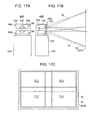
- Fig. 17 is a diagram showing a construction of a front projection type multi-projection display according to a fourth embodiment.
- Fig. 17A is a front view thereof
- Fig. 17B is a cross-sectional view as viewed from a side
- Fig. 1C is a view showing a projection image projected onto the screen.
- Fig. 18 is a block diagram illustrating an outline of the front projection type multi-projection display according to the fourth embodiment.
- reference characters S 1 and S 2 in Fig. 17 show capturing ranges of the image-capturing element 142, respectively.
- the amount of light emitted from the LED light sources is lowered such that the brightness level in the projector units complies with the brightness level in the projector unit having the lowest brightness level.
- the front projection type multi-projection display 700 (not shown) according to the seventh embodiment comprises the solid-state light source control unit 780 (not shown) for controlling the amount of light emitted from the LED light sources for every projector unit, similarly to the front projection type multi-projection display 600 according to the sixth embodiment. Further, the solid-state light source control unit 780 has a function of controlling the amount of light emitted from the LED light sources for every liquid crystal device, similarly to the front projection type multi-projection display 600 according to the sixth embodiment.
- the solid-state light source control unit 780 also has a function of dynamically controlling the amount of light emitted from the LED light sources, in addition to the above-mentioned function.
- a totally dark image for example, a case in which a night scene in a movie is displayed
- lowering the transmittance of the liquid crystal devices by decreasing the amount of light emitted from the LED light sources
- a totally bright screen for example, a case in which an outdoor scene in the daytime in a movie is displayed
- it is possible to make the entire screen bright instead of or in addition to increasing the transmittance of the liquid crystal devices, by increasing the amount of light emitted from the LED light sources, it is possible to make the entire screen bright.
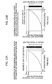
- Fig. 25 is a diagram illustrating advantages of a front projection type multi-projection display according to an eighth embodiment.
- the front projection type multi-projection display 800 (not shown) according to the eighth embodiment comprises the solid-state light source control unit 880 (not shown) for controlling the amount of light emitted from the LED light sources for every projector unit and for every liquid crystal device, similarly to the front projection type multi-projection display 700 according to the seventh embodiment. Further, the solid-state light source control unit 880 also has a function of dynamically controlling the amount of light emitted from the LED light sources, similarly to the front projection type multi-projection display 700 according to the seventh embodiment.
- the front projection type multi-projection display in the case in which an image in which a bright screen and a dark screen exist in one screen is displayed, it is possible for the front projection type multi-projection display to exhibit the expression ability exceeding the number of effective gradation or the dynamic range inherent in the front projection type multi-projection display. In addition, it is possible to perform high image quality display.
- a front projection type multi-projection display 900 (not shown) according to a ninth embodiment comprises the solid-state light source control unit 980 (not shown) for controlling the amount of light emitted from the LED light sources for every projector unit and for every liquid crystal device, similarly to the front projection type multi-projection display 800 according to the eighth embodiment. Further, the solid-state light source control unit 980 also has a function of dynamically controlling the amount of light emitted from the LED light sources for every projector unit.
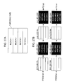
- the front projection type multi-projection display 900 according to the ninth embodiment comprises a liquid crystal device, which perform writing twice or more to one unit image information, as the liquid crystal device. Further, in the front projection type multi-projection display 900 according to the ninth embodiment, the solid-state light source control unit 980 has a function of allowing the solid-state light source to emit during one frame outside at least the first writing period of the liquid crystal devices.
- Fig. 26 is a diagram illustrating operations of the front projection type multi-projection display according to the ninth embodiment.
- Fig. 26A shows a two-time speed driving liquid crystal device
- Fig. 26B shows a three-time speed driving liquid crystal device
- Fig. 26C shows a four-time speed driving liquid crystal device.
- writing is performed twice or more to one unit screen information, and a liquid crystal device of a so-called n-time speed driving (here, n is a natural number of 2 or more) is used.
- the solid-state light source is allowed to emit outside at least the first writing period of the liquid crystal device.
- the liquid crystal molecules do not yet sufficiently response, it is not easy to raise contrast of the liquid crystal device.
- the front projection type multi-projection display 900 of the ninth embodiment since the solid-state light source is allowed to emit outside the first writing period, in the liquid crystal device and the front projection type multi-projection display, it has an advantage that it is possible to further improve contrast.
- the LED light sources are allowed to emit outside the image writing periods of the liquid crystal devices 134R, 134G, and 134B.
- it has an advantage that it is possible to further improve contrast in the front projection type multi-projection display.
- Fig. 28 is a block diagram showing an outline of a front projection type multi-projection display according to an eleventh embodiment.
- the front projection type multi-projection display 1100 according to the eleventh embodiment further comprises an external light state evaluating unit 190 for evaluating a state of external light by capturing a screen in a state when the LED light source does not emit or weakly emits.
- the solid-state light source control unit 1180 has a function of controlling the amount of light emitted from the LED light source taking a result evaluated by the external light state evaluating unit 190 into consideration.
- the effect of the external light on the image quality is non-linear. Therefore, the state of the external light is evaluated by capturing the screen based on an amount of light which is emitted from the LED light source at at least two emitting levels to lessen the effect of the external light during the image capturing process.
Landscapes
- Engineering & Computer Science (AREA)
- Multimedia (AREA)
- Signal Processing (AREA)
- Physics & Mathematics (AREA)
- General Physics & Mathematics (AREA)
- Projection Apparatus (AREA)
- Transforming Electric Information Into Light Information (AREA)
- Video Image Reproduction Devices For Color Tv Systems (AREA)
- Controls And Circuits For Display Device (AREA)
Applications Claiming Priority (2)
| Application Number | Priority Date | Filing Date | Title |
|---|---|---|---|
| JP2003401527 | 2003-12-01 | ||
| PCT/JP2004/018242 WO2005055598A1 (ja) | 2003-12-01 | 2004-12-01 | 前面投写型マルチプロジェクションディスプレイ |
Publications (2)
| Publication Number | Publication Date |
|---|---|
| EP1705907A1 true EP1705907A1 (de) | 2006-09-27 |
| EP1705907A4 EP1705907A4 (de) | 2007-05-02 |
Family
ID=34616711
Family Applications (1)
| Application Number | Title | Priority Date | Filing Date |
|---|---|---|---|
| EP04801622A Withdrawn EP1705907A4 (de) | 2003-12-01 | 2004-12-01 | Frontprojektions-mehrfachprojektions-display |
Country Status (6)
| Country | Link |
|---|---|
| US (1) | US7338175B2 (de) |
| EP (1) | EP1705907A4 (de) |
| JP (1) | JP4661596B2 (de) |
| KR (1) | KR100846031B1 (de) |
| CN (1) | CN100471245C (de) |
| WO (1) | WO2005055598A1 (de) |
Cited By (1)
| Publication number | Priority date | Publication date | Assignee | Title |
|---|---|---|---|---|
| US9324253B2 (en) | 2005-12-06 | 2016-04-26 | Dolby Laboratories Licensing Corporation | Modular electronic displays |
Families Citing this family (31)
| Publication number | Priority date | Publication date | Assignee | Title |
|---|---|---|---|---|
| US7131733B2 (en) * | 2003-03-26 | 2006-11-07 | Matsushita Electric Works, Ltd. | Method for creating brightness filter and virtual space creation system |
| US7410263B2 (en) * | 2003-11-06 | 2008-08-12 | Seiko Epson Corporation | Rear projection type multi-projection display |
| JP2006047531A (ja) * | 2004-08-03 | 2006-02-16 | Seiko Epson Corp | マルチプロジェクションディスプレイ及びプロジェクタユニット |
| JP2008539675A (ja) | 2005-04-26 | 2008-11-13 | アイマックス コーポレイション | 電子投影システムおよび方法 |
| WO2007029997A1 (en) * | 2005-09-05 | 2007-03-15 | Continuum Science And Technologies Sdn Bhd | Display system utilising multiple display units |
| DE102006002602A1 (de) * | 2006-01-13 | 2007-07-19 | Fraunhofer-Gesellschaft zur Förderung der angewandten Forschung e.V. | Kalibrierungsverfahren und Kalibrierungssystem |
| JP4258540B2 (ja) * | 2006-09-01 | 2009-04-30 | セイコーエプソン株式会社 | 情報処理装置、情報処理プログラム、及びその記録媒体 |
| JP4464948B2 (ja) * | 2006-10-13 | 2010-05-19 | 株式会社日立製作所 | 投写型映像表示システム |
| US8994757B2 (en) | 2007-03-15 | 2015-03-31 | Scalable Display Technologies, Inc. | System and method for providing improved display quality by display adjustment and image processing using optical feedback |
| US20090021702A1 (en) * | 2007-07-20 | 2009-01-22 | Cleland Todd A | Multi-projection kiosk for digital signage |
| US7954954B2 (en) * | 2007-07-31 | 2011-06-07 | Hewlett-Packard Development Company, L.P. | System and method of projecting an image using a plurality of projectors |
| US8319699B2 (en) * | 2007-08-09 | 2012-11-27 | Barco N.V. | Multiple display channel system with high dynamic range |
| JP5218739B2 (ja) * | 2008-02-08 | 2013-06-26 | セイコーエプソン株式会社 | プロジェクタ、投写システムおよび投写方法 |
| JP5217496B2 (ja) * | 2008-02-26 | 2013-06-19 | ソニー株式会社 | 画像投影システム、制御装置、画像投影方法、プログラム及び記録媒体 |
| KR20100077851A (ko) * | 2008-12-29 | 2010-07-08 | 엘지전자 주식회사 | Dtv 및 이를 이용한 콘텐츠 표시 방법 |
| US8567961B2 (en) | 2009-05-04 | 2013-10-29 | Kenneth J. Huebner | Light array projection and sensing system |
| US8100540B2 (en) | 2009-05-04 | 2012-01-24 | Huebner Kenneth J | Light array projection and sensing system |
| US20100321382A1 (en) * | 2009-06-18 | 2010-12-23 | Scalable Display Technologies, Inc. | System and method for injection of mapping functions |
| US9110495B2 (en) * | 2010-02-03 | 2015-08-18 | Microsoft Technology Licensing, Llc | Combined surface user interface |
| JP5604909B2 (ja) * | 2010-02-26 | 2014-10-15 | セイコーエプソン株式会社 | 補正情報算出装置、画像処理装置、画像表示システム、および画像補正方法 |
| US20130249780A1 (en) * | 2011-01-11 | 2013-09-26 | Kenji Ishida | Projection display and lack of brightness uniformity compensation method |
| JP5924020B2 (ja) * | 2012-02-16 | 2016-05-25 | セイコーエプソン株式会社 | プロジェクター、及び、プロジェクターの制御方法 |
| JP6140987B2 (ja) * | 2012-03-27 | 2017-06-07 | キヤノン株式会社 | 画像処理装置および画像処理方法 |
| JP6089461B2 (ja) * | 2012-06-22 | 2017-03-08 | セイコーエプソン株式会社 | プロジェクター、画像表示システム、プロジェクターの制御方法 |
| CN103324017B (zh) * | 2013-06-17 | 2015-07-22 | 杭州曼加科技有限公司 | 基于led投影模组结构的多媒体信息显示系统 |
| JP6421445B2 (ja) * | 2014-01-24 | 2018-11-14 | 株式会社リコー | 投影システム、画像処理装置、校正方法、システムおよびプログラム |
| CN105530447A (zh) * | 2014-09-28 | 2016-04-27 | 联想(北京)有限公司 | 一种信息处理方法及电子设备 |
| JP6525570B2 (ja) * | 2014-12-04 | 2019-06-05 | キヤノン株式会社 | 画像表示システム、制御装置、制御方法及びプログラム |
| TWI611383B (zh) * | 2015-03-03 | 2018-01-11 | 宏正自動科技股份有限公司 | 多影像輸出裝置校正系統及其校正方法 |
| JP6630363B2 (ja) | 2015-10-27 | 2020-01-15 | マクセル株式会社 | プロジェクタ、映像表示装置、及び映像表示方法 |
| JP6471717B2 (ja) * | 2016-03-30 | 2019-02-20 | ブラザー工業株式会社 | 投影制御装置、プログラム、及び投影システム |
Family Cites Families (39)
| Publication number | Priority date | Publication date | Assignee | Title |
|---|---|---|---|---|
| JPH0630728B2 (ja) * | 1990-03-01 | 1994-04-27 | 昭和アルミニウム株式会社 | 耐水密着性に優れた下地皮膜を有する熱交換器用フィンの製造方法 |
| JP3136003B2 (ja) | 1992-08-27 | 2001-02-19 | 日本電信電話株式会社 | 投射形表示装置 |
| JP3534785B2 (ja) | 1992-12-08 | 2004-06-07 | 松下電器産業株式会社 | 高臨場映像表示方法とその装置 |
| JP3533475B2 (ja) * | 1994-04-05 | 2004-05-31 | カシオ計算機株式会社 | 液晶表示装置 |
| JPH0882854A (ja) | 1994-09-14 | 1996-03-26 | Hitachi Ltd | マルチビジョンのスクリーン装置 |
| JPH0894974A (ja) | 1994-09-28 | 1996-04-12 | Matsushita Electric Ind Co Ltd | リアプロジェクション装置 |
| US5589985A (en) | 1995-06-09 | 1996-12-31 | Heller; Philip | Computer monitor hood |
| JPH09200662A (ja) | 1996-01-17 | 1997-07-31 | Mitsubishi Electric Corp | 投射型液晶表示装置 |
| EP0786687A1 (de) | 1996-01-29 | 1997-07-30 | Hughes-Jvc Technology Corporation | Projizierte Bildeinblendung von mehrfachen Bildern |
| JP3735158B2 (ja) | 1996-06-06 | 2006-01-18 | オリンパス株式会社 | 画像投影システム、画像処理装置 |
| US5956000A (en) | 1997-05-12 | 1999-09-21 | Scitex Corporation Ltd. | Digital image display system and method |
| JP3799829B2 (ja) * | 1997-09-11 | 2006-07-19 | セイコーエプソン株式会社 | 電気光学装置およびその製造方法並びに投射型表示装置 |
| JP2002503892A (ja) | 1997-09-17 | 2002-02-05 | コムヴュー グラフィックス リミテッド | 電気光学表示装置 |
| NO316115B1 (no) * | 1997-12-10 | 2003-12-15 | Akva As | Fremgangsmåte og anordning for dosert utmating av et kornet, pelletert eller granulert massegods ut av en beholder |
| JP3714163B2 (ja) | 1997-12-12 | 2005-11-09 | 株式会社日立製作所 | 映像表示システム |
| US6050690A (en) * | 1998-01-08 | 2000-04-18 | Siemens Information And Communication Networks, Inc. | Apparatus and method for focusing a projected image |
| US6310650B1 (en) | 1998-09-23 | 2001-10-30 | Honeywell International Inc. | Method and apparatus for calibrating a tiled display |
| JP2000275605A (ja) * | 1999-03-25 | 2000-10-06 | Toshiba Corp | 液晶表示装置 |
| JP2000350230A (ja) | 1999-06-07 | 2000-12-15 | Olympus Optical Co Ltd | 画像投影システム |
| US6254239B1 (en) * | 1999-07-30 | 2001-07-03 | Raytheon Company | Method and system for image visualization |
| JP2001147667A (ja) | 1999-11-18 | 2001-05-29 | Hitachi Ltd | 液晶モニタ装置 |
| JP2001166377A (ja) * | 1999-12-09 | 2001-06-22 | Olympus Optical Co Ltd | 画像投影システム |
| JP4776055B2 (ja) | 2000-03-06 | 2011-09-21 | ガリストロフ ソフトウェア エルエルシー | 映像調整システム装置 |
| JP2001339672A (ja) | 2000-03-24 | 2001-12-07 | Olympus Optical Co Ltd | マルチビジョン装置 |
| JP3497805B2 (ja) * | 2000-08-29 | 2004-02-16 | オリンパス株式会社 | 画像投影表示装置 |
| JP2002094822A (ja) * | 2000-09-13 | 2002-03-29 | Seiko Epson Corp | 補正カーブ生成方法、画像処理方法、画像表示装置および記録媒体 |
| KR100381050B1 (ko) * | 2000-12-02 | 2003-04-18 | 엘지전자 주식회사 | 액정 프로젝터의 광학계 |
| US6814443B2 (en) * | 2001-09-26 | 2004-11-09 | Digital Advertising Network Inc | Image projection system and its method of use |
| JP3705180B2 (ja) * | 2001-09-27 | 2005-10-12 | セイコーエプソン株式会社 | 画像表示システム、プログラム、情報記憶媒体および画像処理方法 |
| US6974217B2 (en) * | 2002-03-20 | 2005-12-13 | Seiko Epson Corporation | Projector executing keystone correction |
| US6648475B1 (en) * | 2002-05-20 | 2003-11-18 | Eastman Kodak Company | Method and apparatus for increasing color gamut of a display |
| JP4027747B2 (ja) * | 2002-08-07 | 2007-12-26 | オリンパス株式会社 | 照明装置及び投影表示装置 |
| US6834965B2 (en) * | 2003-03-21 | 2004-12-28 | Mitsubishi Electric Research Laboratories, Inc. | Self-configurable ad-hoc projector cluster |
| JP3620537B2 (ja) * | 2003-05-02 | 2005-02-16 | セイコーエプソン株式会社 | 画像処理システム、プロジェクタ、プログラム、情報記憶媒体および画像処理方法 |
| US6886943B1 (en) | 2003-10-24 | 2005-05-03 | Jds Uniphase Corporation | High-resolution projection display system |
| US7410263B2 (en) | 2003-11-06 | 2008-08-12 | Seiko Epson Corporation | Rear projection type multi-projection display |
| JP4752638B2 (ja) * | 2006-06-21 | 2011-08-17 | 住友化学株式会社 | 繊維およびネット |
| JP2008003021A (ja) * | 2006-06-26 | 2008-01-10 | Matsushita Electric Ind Co Ltd | 自律走行装置およびプログラム |
| JP2008004012A (ja) * | 2006-06-26 | 2008-01-10 | Canon Inc | デバイス自動停止方法を備えたコンピュータ装置 |
-
2004
- 2004-11-29 US US10/998,225 patent/US7338175B2/en not_active Expired - Fee Related
- 2004-12-01 CN CNB2004800410091A patent/CN100471245C/zh not_active Expired - Fee Related
- 2004-12-01 WO PCT/JP2004/018242 patent/WO2005055598A1/ja not_active Ceased
- 2004-12-01 EP EP04801622A patent/EP1705907A4/de not_active Withdrawn
- 2004-12-01 JP JP2005516024A patent/JP4661596B2/ja not_active Expired - Fee Related
- 2004-12-01 KR KR1020067013275A patent/KR100846031B1/ko not_active Expired - Fee Related
Cited By (1)
| Publication number | Priority date | Publication date | Assignee | Title |
|---|---|---|---|---|
| US9324253B2 (en) | 2005-12-06 | 2016-04-26 | Dolby Laboratories Licensing Corporation | Modular electronic displays |
Also Published As
| Publication number | Publication date |
|---|---|
| CN1906933A (zh) | 2007-01-31 |
| JP4661596B2 (ja) | 2011-03-30 |
| WO2005055598A1 (ja) | 2005-06-16 |
| US7338175B2 (en) | 2008-03-04 |
| KR100846031B1 (ko) | 2008-07-11 |
| JPWO2005055598A1 (ja) | 2007-12-06 |
| EP1705907A4 (de) | 2007-05-02 |
| KR20060096164A (ko) | 2006-09-07 |
| CN100471245C (zh) | 2009-03-18 |
| US20050117126A1 (en) | 2005-06-02 |
Similar Documents
| Publication | Publication Date | Title |
|---|---|---|
| US7338175B2 (en) | Front projection type multi-projection display | |
| US7926957B2 (en) | Multi-projection display | |
| US7410263B2 (en) | Rear projection type multi-projection display | |
| JP4059271B2 (ja) | 投射型表示装置 | |
| US8605106B2 (en) | Projector and color improvement method of the projector | |
| US10148924B2 (en) | Projection apparatus, method of controlling projection apparatus, and projection system | |
| JPWO2016157670A1 (ja) | 画像表示装置、画像表示方法、情報処理装置、情報処理方法、及びプログラム | |
| US20060119561A1 (en) | Image display apparatus, image signal converting device, image signal converting method, image signal converting program | |
| JPH08179727A (ja) | 液晶プロジェクタ | |
| JP4862866B2 (ja) | 画像表示装置および画像表示方法 | |
| JP2004304479A (ja) | 投射型映像表示装置、輝度制御方法及びプログラム | |
| JP4595961B2 (ja) | 投射型表示装置 | |
| JP2015126462A (ja) | 投影装置 | |
| JPH08146922A (ja) | 液晶プロジェクタ | |
| JP4683022B2 (ja) | 投射型表示装置 | |
| JP2023036183A (ja) | プロジェクター、及びプロジェクターの制御方法 | |
| JP2007003577A (ja) | 画像表示装置、画像表示装置の調整装置、画像表示方法及び画像表示装置の調整方法 |
Legal Events
| Date | Code | Title | Description |
|---|---|---|---|
| PUAI | Public reference made under article 153(3) epc to a published international application that has entered the european phase |
Free format text: ORIGINAL CODE: 0009012 |
|
| 17P | Request for examination filed |
Effective date: 20060630 |
|
| AK | Designated contracting states |
Kind code of ref document: A1 Designated state(s): AT BE BG CH CY CZ DE DK EE ES FI FR GB GR HU IE IS IT LI LT LU MC NL PL PT RO SE SI SK TR |
|
| DAX | Request for extension of the european patent (deleted) | ||
| A4 | Supplementary search report drawn up and despatched |
Effective date: 20070329 |
|
| RIN1 | Information on inventor provided before grant (corrected) |
Inventor name: HASEGAWA, HIROSHI Inventor name: MIYAZAWA, YASUNAGA |
|
| 17Q | First examination report despatched |
Effective date: 20080115 |
|
| STAA | Information on the status of an ep patent application or granted ep patent |
Free format text: STATUS: THE APPLICATION IS DEEMED TO BE WITHDRAWN |
|
| 18D | Application deemed to be withdrawn |
Effective date: 20090121 |