EP1705953A2 - Hörhilfevorrichtung mit optischem Mikrofon - Google Patents
Hörhilfevorrichtung mit optischem Mikrofon Download PDFInfo
- Publication number
- EP1705953A2 EP1705953A2 EP06111591A EP06111591A EP1705953A2 EP 1705953 A2 EP1705953 A2 EP 1705953A2 EP 06111591 A EP06111591 A EP 06111591A EP 06111591 A EP06111591 A EP 06111591A EP 1705953 A2 EP1705953 A2 EP 1705953A2
- Authority
- EP
- European Patent Office
- Prior art keywords
- optical
- microphones
- microphone
- hearing aid
- aid device
- Prior art date
- Legal status (The legal status is an assumption and is not a legal conclusion. Google has not performed a legal analysis and makes no representation as to the accuracy of the status listed.)
- Granted
Links
Images
Classifications
-
- H—ELECTRICITY
- H04—ELECTRIC COMMUNICATION TECHNIQUE
- H04R—LOUDSPEAKERS, MICROPHONES, GRAMOPHONE PICK-UPS OR LIKE ACOUSTIC ELECTROMECHANICAL TRANSDUCERS; ELECTRIC HEARING AIDS; PUBLIC ADDRESS SYSTEMS
- H04R23/00—Transducers other than those covered by groups H04R9/00 - H04R21/00
- H04R23/008—Transducers other than those covered by groups H04R9/00 - H04R21/00 using optical signals for detecting or generating sound
-
- H—ELECTRICITY
- H04—ELECTRIC COMMUNICATION TECHNIQUE
- H04R—LOUDSPEAKERS, MICROPHONES, GRAMOPHONE PICK-UPS OR LIKE ACOUSTIC ELECTROMECHANICAL TRANSDUCERS; ELECTRIC HEARING AIDS; PUBLIC ADDRESS SYSTEMS
- H04R2225/00—Details of deaf aids covered by H04R25/00, not provided for in any of its subgroups
- H04R2225/021—Behind the ear [BTE] hearing aids
-
- H—ELECTRICITY
- H04—ELECTRIC COMMUNICATION TECHNIQUE
- H04R—LOUDSPEAKERS, MICROPHONES, GRAMOPHONE PICK-UPS OR LIKE ACOUSTIC ELECTROMECHANICAL TRANSDUCERS; ELECTRIC HEARING AIDS; PUBLIC ADDRESS SYSTEMS
- H04R2225/00—Details of deaf aids covered by H04R25/00, not provided for in any of its subgroups
- H04R2225/023—Completely in the canal [CIC] hearing aids
-
- H—ELECTRICITY
- H04—ELECTRIC COMMUNICATION TECHNIQUE
- H04R—LOUDSPEAKERS, MICROPHONES, GRAMOPHONE PICK-UPS OR LIKE ACOUSTIC ELECTROMECHANICAL TRANSDUCERS; ELECTRIC HEARING AIDS; PUBLIC ADDRESS SYSTEMS
- H04R2225/00—Details of deaf aids covered by H04R25/00, not provided for in any of its subgroups
- H04R2225/025—In the ear hearing aids [ITE] hearing aids
-
- H—ELECTRICITY
- H04—ELECTRIC COMMUNICATION TECHNIQUE
- H04R—LOUDSPEAKERS, MICROPHONES, GRAMOPHONE PICK-UPS OR LIKE ACOUSTIC ELECTROMECHANICAL TRANSDUCERS; ELECTRIC HEARING AIDS; PUBLIC ADDRESS SYSTEMS
- H04R2225/00—Details of deaf aids covered by H04R25/00, not provided for in any of its subgroups
- H04R2225/67—Implantable hearing aids or parts thereof not covered by H04R25/606
Definitions
- the present invention relates to a hearing aid device with at least one microphone.
- the present invention also relates to implants.
- Hearing aids have one or more microphones.
- the hearing aids use electret microphones.
- this or their downstream signal processing show problems with electromagnetic compatibility (EMC). This is due to the fact that the microphone cables act as an antenna and the impedance converter in the microphone as a demodulator.
- EMC electromagnetic compatibility
- the electromagnetic waves, which are coupled via the microphone lines, can also be demodulated in the preamplifier.
- Modern hearing aids are often equipped with two or three microphones to achieve a directivity.
- the electrical connections of three microphones can then be realized, for example, with nine connecting stranded wires. This is a very complex mechanical structure, which is also relatively susceptible to interference.
- the object of the present invention is to simplify the construction of a hearing aid device and at the same time to increase its electromagnetic compatibility.
- this object is achieved by a hearing aid device having at least one microphone, which is designed as an optical microphone.
- the input side signal processing is carried out partially by optical means, wherein the sound signal is first converted via an acousto-optical converter into an optical signal before it is converted by an opto-electrical converter into an electrical signal.
- An advantage of using an optical microphone is that it has no metal parts, so that there are no risks of corrosion.
- the optical signal processing can avoid the EMC problems.
- microphone arrays are made of optical microphones, since thus can be dispensed with a large number of strands.
- cerumen protection can be easily realized because optical microphones have a moisture-insensitive structure.
- optical microphones offer significant advantages in the field of action of magnetic fields, since they are insensitive to them.
- the hearing aid according to the invention has a plurality of optical microphones, which are connected to a common optical fiber. This results in significant advantages, especially compared to a three-wire cabling of an electret microphone.
- the at least one optical microphone can be connected via a multimode fiber to an amplifier with an optical input. Thus, a plurality of modes can be forwarded from the optical microphone to the evaluation.
- the hearing aid device may have a laser diode for supplying the optical microphone.
- an energetically favorable light source can be used for the optical microphone.
- a laser diode each having a different wavelength may be employed for each of the plurality of optical microphones.
- a common evaluation with appropriate filters can be used for each of the plurality of optical microphones.
- a polarization device can be provided in the hearing aid device, so that the light of a first of the plurality of optical microphones can be polarized differently than the light of a second of the plurality of optical microphones.
- a common processing unit can be used when a corresponding electronically controlled polarizing filter is used to filter out the desired polarization.
- the membranes of the plurality of microphones each have different reflectance.
- the individual microphones can be evaluated in a simple manner depending on their amplitude.
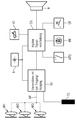
- the hearing aid selected in the embodiment has three optical microphones M1, M2 and M3.
- a membrane is scanned with suitable optics, which is deflected by the incident sound.
- the microphones M1, M2 and M3 form a so-called microphone array, with which, for example, the functionality of a directional microphone can be ensured.
- hearing aids with two, four, five, etc. optical microphones can be realized.
- the individual microphones M1, M2 and M3 are supplied via a common multi-mode fiber MF, which is branched correspondingly, with the light of a laser diode, which is arranged in the control and preprocessing unit SV.
- this control and preprocessing unit SV also includes a preamplifier with an optical input so that the optical signals arriving via the multimode fiber MF from the individual microphones M1, M2 and M3 can be preamplified.
- each individual microphone M1, M2 and M3 have their own optical connection, each with its own fiber optic cable to the control and preprocessing unit SV (not shown in the figure).
- control and preprocessing unit SV not shown in the figure.
- a telecoil TS is furthermore provided as the input unit for the control and preprocessing unit SV.
- the output signal of the control and preprocessing unit SV is supplied to a digital signal processor DS with a clocked output stage.
- the digital signal processing DS is a program switch MTO, a programming socket PB, a situation key ST and a VC-controller VC controllable.
- a battery B supplies the control and preprocessing unit SV and the digital signal processing DS.
- the output signal of the digital signal processing DS is supplied to a receiver H.
- the modulated signals are sent back via the branched multi-mode fiber MF to the control and preprocessing unit SV and processed there individually.
- the individual optical signals are distinguished on the basis of the light intensity, the color or the polarization.
- the optical signals are then converted into electrical analog signals and then converted to digital signals. The further signal processing takes place as in conventional hearing aids.
- the robust, interference-free optical microphones are especially suitable for the realization of microphone arrays in hearing aids.
Landscapes
- Physics & Mathematics (AREA)
- Engineering & Computer Science (AREA)
- Acoustics & Sound (AREA)
- Signal Processing (AREA)
- Electrostatic, Electromagnetic, Magneto- Strictive, And Variable-Resistance Transducers (AREA)
- Details Of Audible-Bandwidth Transducers (AREA)
Abstract
Description
- Die vorliegende Erfindung betrifft eine Hörhilfevorrichtung mit mindestens einem Mikrofon. Insbesondere betrifft die vorliegende Erfindung neben üblichen Hinter-dem-Ohr-Hörgeräten und In-dem-Ohr-Hörgeräten auch Implantate.
- Hörhilfegeräte besitzen ein oder mehrere Mikrofone. Typischerweise werden in den Hörhilfegeräten Elektretmikrofone eingesetzt. Diese bzw. ihre nachgeschaltete Signalverarbeitung zeigen jedoch Probleme hinsichtlich der elektromagnetischen Verträglichkeit (EMV). Dies liegt zum einen daran, dass die Mikrofonleitungen als Antenne und der Impedanzwandler im Mikrofon als Demodulator wirken. Die elektromagnetischen Wellen, die über die Mikrofonleitungen eingekoppelt werden, können auch bereits im Vorverstärker demoduliert werden.
- Weiterhin besitzen konventionelle Mikrofone eine hohe Empfindlichkeit gegenüber Feuchtigkeit. Zu hohe Luftfeuchtigkeit führt häufig zu einem Ausfall des Geräts.
- Moderne Hörgeräte sind vielfach mit zwei oder drei Mikrofonen ausgestattet, um eine Richtwirkung zu erzielen. Die elektrischen Anschlüsse von drei Mikrofonen sind dann beispielsweise mit neun Anschlusslitzendrähten zu realisieren. Damit liegt ein sehr aufwendiger mechanischer Aufbau vor, der auch verhältnismäßig störanfällig ist.
- An dem aufwendigen Aufbau führte bislang kein Weg vorbei. Lediglich die elektromagnetische Verträglichkeit der Mikrofone und des Mikrofoneingangsverstärkers konnte durch Einbau von HF-Filtern verbessert werden.
- In dem Artikel "Optisches Mikrofon" von Peter Schreiber et al., Fraunhofer IOF Jahresbericht 2003, Seiten 84 bis 87, ist ein Mikrofon mit optischer Abtastung beschrieben. Dabei erfolgt die Detektion von Schallwellen an einer Mikrofonmembran. Mit diesem Sensorprinzip sind auch konfokale Mikrofone realisierbar.
- Die Aufgabe der vorliegenden Erfindung besteht darin, den Aufbau einer Hörhilfevorrichtung zu vereinfachen und gleichzeitig deren elektromagnetische Verträglichkeit zu erhöhen.
- Erfindungsgemäß wird diese Aufgabe gelöst durch eine Hörhilfevorrichtung mit mindestens einem Mikrofon, das als optisches Mikrofon ausgestaltet ist. Somit erfolgt die eingangsseitige Signalverarbeitung teilweise auf optischem Wege, wobei das Schallsignal zunächst über einen akustooptischen Wandler in ein optisches Signal umgesetzt wird, bevor es durch einen optoelektrischen Wandler in ein elektrisches Signal gewandelt wird.
- Vorteilhaft an dem Einsatz eines optischen Mikrofons ist, dass dieses keine Metallteile aufweist, so dass keine Korrosionsgefahren bestehen. Darüber hinaus können durch die optische Signalverarbeitung die EMV-Probleme vermieden werden.
- Außerdem erweist es sich als vorteilhaft, wenn Mikrofonarrays aus optischen Mikrofonen hergestellt werden, da somit auf eine große Anzahl von Litzen verzichtet werden kann. Ferner lässt sich der Cerumenschutz einfach realisieren, da optische Mikrofone einen feuchteunempfindlichen Aufbau besitzen. Nicht zuletzt bieten optische Mikrofone deutliche Vorteile im Wirkungsbereich von Magnetfeldern, da sie ihnen gegenüber unempfindlich sind.
- Vorzugsweise verfügt die erfindungsgemäße Hörhilfevorrichtung über mehrere optische Mikrofone, welche an eine gemeinsame Lichtleitfaser angeschlossen sind. Damit ergeben sich deutliche Vorteile, insbesondere gegenüber einer dreiadrigen Verkabelung eines Elektretmikrofons.
- Das mindestens eine optische Mikrofon kann über eine Multimodefaser an einen Verstärker mit optischem Eingang angeschlossen sein. Damit können eine Vielzahl von Moden von dem optischen Mikrofon zur Auswerteeinrichtung weitergeleitet werden.
- Darüber hinaus kann die Hörhilfevorrichtung eine Laserdiode zur Versorgung des optischen Mikrofons aufweisen. Somit kann eine energetisch günstige Lichtquelle für das optische Mikrofon genutzt werden.
- Ferner kann für jedes der mehreren optischen Mikrofone eine Laserdiode mit jeweils einer anderen Wellenlänge eingesetzt sein. Damit kann eine gemeinsame Auswerteeinheit mit entsprechenden Filtern verwendet werden.
- Entsprechend einer weiteren Ausführungsform kann in der Hörhilfevorrichtung eine Polarisationseinrichtung vorgesehen sein, so dass das Licht eines ersten der mehreren optischen Mikrofone anders als das Licht eines zweiten der mehreren optischen Mikrofone polarisierbar ist. Auch bei dieser Ausgestaltung kann eine gemeinsame Verarbeitungseinheit verwendet werden, wenn ein entsprechendes elektronisch gesteuertes Polarisationsfilter zur Ausfilterung der gewünschten Polarisation eingesetzt wird.
- Bei einer weiteren Ausführungsform ist vorgesehen, dass die Membranen der mehreren Mikrofone jeweils unterschiedlichen Reflexionsgrad aufweisen. Damit können die einzelnen Mikrofone in Abhängigkeit ihrer Amplitude auf einfache Weise ausgewertet werden.
- Die vorliegende Erfindung wird nun anhand der beigefügten Zeichnung näher erläutert, die ein Prinzipschaltbild eines erfindungsgemäßen Hörhilfegeräts mit optischen Mikrofonen darstellt.
- Das nachfolgend näher geschilderte Ausführungsbeispiel stellt eine bevorzugte Ausführungsform der vorliegenden Erfindung dar.
- Das in dem Ausführungsbeispiel gewählte Hörhilfegerät besitzt drei optische Mikrofone M1, M2 und M3. In jedem optischen Mikrofon wird mit einer geeigneten Optik eine Membran abgetastet, die durch den einfallenden Schall ausgelenkt wird. Die Mikrofone M1, M2 und M3 bilden ein sogenanntes Mikrofon-Array, mit dem beispielsweise die Funktionalität eines Richtmikrofons gewährleistet werden kann. Selbstverständlich können auch Hörhilfegeräte mit zwei, vier, fünf usw. optischen Mikrofonen realisiert werden.
- Die einzelnen Mikrofone M1, M2 und M3 werden über eine gemeinsame Multimodefaser MF, die entsprechend verzweigt wird, mit dem Licht einer Laserdiode versorgt, die in der Steuer- und Vorverarbeitungseinheit SV angeordnet ist. Neben dem optischen Ausgang beinhaltet diese Steuer- und Vorverarbeitungseinheit SV auch einen Vorverstärker mit optischem Eingang, so dass die über die Multimodefaser MF von den einzelnen Mikrofonen M1, M2 und M3 eingehenden optischen Signale vorverstärkt werden können.
- Alternativ kann jedes einzelne Mikrofon M1, M2 und M3 eine eigene optische Verbindung mit jeweils einem eigenen Glasfaserkabel zu der Steuer- und Vorverarbeitungseinheit SV besitzen (in der Figur nicht dargestellt). Dadurch können zwar einfache, kostengünstige Glasfaserkabel ohne Verzweigungen eingesetzt werden, aber es erhöht sich der Signalverarbeitungsaufwand in der Steuer- und Vorverarbeitungseinheit SV.
- Bei dem beispielhaft dargestellten Hörhilfegerät ist weiterhin eine Telefonspule TS als Eingangseinheit für die Steuer- und Vorverarbeitungseinheit SV vorgesehen. Das Ausgangssignal der Steuer- und Vorverarbeitungseinheit SV wird einer digitalen Signalverarbeitung DS mit getakteter Endstufe zugeführt. Die digitale Signalverarbeitung DS ist von einem Programmschalter MTO, einer Programmierbuchse PB, einer Situationstaste ST und einem VC-Steller VC ansteuerbar. Eine Batterie B versorgt die Steuer- und Vorverarbeitungseinheit SV und die digitale Signalverarbeitung DS. Das Ausgangssignal der digitalen Signalverarbeitung DS wird einem Hörer H zugeführt.
- Fällt nun Schall auf die Membranen der Mikrofone M1, M2 und M3, so wird das in diese Mikrofone M1, M2 und M3 geschickte Licht bei der Reflexion entsprechend moduliert wird. Die modulierten Signale werden über die verzweigte Multimodefaser MF an die Steuer- und Vorverarbeitungseinheit SV zurückgesandt und dort einzeln verarbeitet. Dabei werden die einzelnen optischen Signale anhand der Lichtstärke, der Farbe oder der Polarisation unterschieden. Die optischen Signale werden daraufhin in elektrische Analogsignale umgesetzt und anschließend zu Digitalsignalen gewandelt. Die weitere Signalverarbeitung erfolgt wie bei üblichen Hörhilfegeräten.
- Zusammenfassend lässt sich feststellen, dass die robusten, störungsunanfälligen optischen Mikrofone speziell für die Realisierung von Mikrofonarrays bei Hörhilfegeräten eignen.
Claims (7)
- Hörhilfevorrichtung mit- mindestens einem Mikrofon (M1, M2, M3)dadurch gekennzeichnet, dass- das mindestens eine Mikrofon (M1, M2, M3) ein optisches Mikrofon ist.
- Hörhilfevorrichtung nach Anspruch 1, die über mehrere optische Mikrofone (M1, M2, M3) verfügt, welche an eine gemeinsame Lichtleitfaser (MF) angeschlossen sind.
- Hörhilfevorrichtung nach Anspruch 1 oder 2, wobei das mindestens eine optische Mikrofon (M1, M2, M3) über eine Multimodefaser (MF) an einen Verstärker mit optischem Eingang angeschlossen ist.
- Hörhilfevorrichtung nach einem der vorhergehenden Ansprüche, die eine Laserdiode zur Versorgung des optischen Mikrofons (M1, M2, M3) mit Licht aufweist.
- Hörhilfevorrichtung nach einem der Ansprüche 2 bis 4, wobei für jedes der mehreren optischen Mikrofone (M1, M2, M3) eine Laserdiode mit jeweils einer anderen Wellenlänge eingesetzt ist.
- Hörhilfevorrichtung nach einem der Ansprüche 2 bis 4, die eine Polarisationseinrichtung aufweist, so dass das Licht eines ersten der mehreren optischen Mikrofone (M1, M2, M3) anders als das Licht eines zweiten der mehreren optischen Mikrofone (M1, M2, M3) polarisierbar ist.
- Hörhilfevorrichtung nach einem der Ansprüche 2 bis 4, wobei die Membranen der mehreren optischen Mikrofone (M1, M2, M3) jeweils einen unterschiedlichen Reflexionsgrad aufweisen.
Applications Claiming Priority (1)
| Application Number | Priority Date | Filing Date | Title |
|---|---|---|---|
| DE102005013833A DE102005013833B3 (de) | 2005-03-24 | 2005-03-24 | Hörhilfevorrichtung mit optischem Mikrofon |
Publications (3)
| Publication Number | Publication Date |
|---|---|
| EP1705953A2 true EP1705953A2 (de) | 2006-09-27 |
| EP1705953A3 EP1705953A3 (de) | 2012-08-22 |
| EP1705953B1 EP1705953B1 (de) | 2016-06-22 |
Family
ID=36500463
Family Applications (1)
| Application Number | Title | Priority Date | Filing Date |
|---|---|---|---|
| EP06111591.1A Expired - Lifetime EP1705953B1 (de) | 2005-03-24 | 2006-03-23 | Hörhilfevorrichtung mit optischem Mikrofon |
Country Status (4)
| Country | Link |
|---|---|
| US (1) | US7711130B2 (de) |
| EP (1) | EP1705953B1 (de) |
| DE (1) | DE102005013833B3 (de) |
| DK (1) | DK1705953T3 (de) |
Families Citing this family (36)
| Publication number | Priority date | Publication date | Assignee | Title |
|---|---|---|---|---|
| US8295523B2 (en) | 2007-10-04 | 2012-10-23 | SoundBeam LLC | Energy delivery and microphone placement methods for improved comfort in an open canal hearing aid |
| US7867160B2 (en) | 2004-10-12 | 2011-01-11 | Earlens Corporation | Systems and methods for photo-mechanical hearing transduction |
| US7668325B2 (en) | 2005-05-03 | 2010-02-23 | Earlens Corporation | Hearing system having an open chamber for housing components and reducing the occlusion effect |
| US8401212B2 (en) | 2007-10-12 | 2013-03-19 | Earlens Corporation | Multifunction system and method for integrated hearing and communication with noise cancellation and feedback management |
| DE102006046700A1 (de) * | 2006-10-02 | 2008-04-10 | Siemens Audiologische Technik Gmbh | Hinter-dem-Ohr-Hörgerät mit externem, optischem Mikrofon |
| US8396239B2 (en) | 2008-06-17 | 2013-03-12 | Earlens Corporation | Optical electro-mechanical hearing devices with combined power and signal architectures |
| WO2009155361A1 (en) | 2008-06-17 | 2009-12-23 | Earlens Corporation | Optical electro-mechanical hearing devices with combined power and signal architectures |
| WO2009155358A1 (en) | 2008-06-17 | 2009-12-23 | Earlens Corporation | Optical electro-mechanical hearing devices with separate power and signal components |
| EP3509324B1 (de) | 2008-09-22 | 2023-08-16 | Earlens Corporation | Ausgewogene ankervorrichtungen und verfahren zum hören |
| DE102009015758A1 (de) * | 2009-04-01 | 2010-06-02 | Siemens Medical Instruments Pte. Ltd. | Hörhilfegerät |
| JP5326039B2 (ja) | 2009-04-06 | 2013-10-30 | ヴェーデクス・アクティーセルスカプ | データバス接続を有する2つの部分からなる補聴器 |
| DK2438768T3 (en) | 2009-06-05 | 2016-06-06 | Earlens Corp | Optically coupled acoustically mellemøreimplantatindretning |
| US9544700B2 (en) | 2009-06-15 | 2017-01-10 | Earlens Corporation | Optically coupled active ossicular replacement prosthesis |
| CN102598713A (zh) | 2009-06-18 | 2012-07-18 | 音束有限责任公司 | 用于听力系统的耳膜可植入装置及方法 |
| CN102640435B (zh) | 2009-06-18 | 2016-11-16 | 伊尔莱茵斯公司 | 光学耦合的耳蜗植入系统及方法 |
| WO2011005479A2 (en) | 2009-06-22 | 2011-01-13 | SoundBeam LLC | Optically coupled bone conduction systems and methods |
| BRPI1016075A2 (pt) * | 2009-06-22 | 2016-05-10 | SoundBeam LLC | dispositivo para transmitir som para um ouvido de um usuário e métodos associados. |
| US8845705B2 (en) | 2009-06-24 | 2014-09-30 | Earlens Corporation | Optical cochlear stimulation devices and methods |
| US8715154B2 (en) | 2009-06-24 | 2014-05-06 | Earlens Corporation | Optically coupled cochlear actuator systems and methods |
| DE102009051771A1 (de) | 2009-10-29 | 2011-05-05 | Moldenhauer, Martin, Dipl.-Ing. | Voll implantierbares optisches Mikrofon |
| EP3758394A1 (de) | 2010-12-20 | 2020-12-30 | Earlens Corporation | Anatomisch angepasstes gehörgangs-hörgerät |
| WO2011064411A2 (en) | 2011-03-17 | 2011-06-03 | Advanced Bionics Ag | Implantable microphone |
| US20140072146A1 (en) * | 2012-09-13 | 2014-03-13 | DSP Group | Optical microphone and method for detecting body conducted sound signals |
| US10034103B2 (en) | 2014-03-18 | 2018-07-24 | Earlens Corporation | High fidelity and reduced feedback contact hearing apparatus and methods |
| DK3169396T3 (da) | 2014-07-14 | 2021-06-28 | Earlens Corp | Glidende forspænding og peak-begrænsning for optiske høreapparater |
| US9924276B2 (en) | 2014-11-26 | 2018-03-20 | Earlens Corporation | Adjustable venting for hearing instruments |
| DK3888564T3 (da) | 2015-10-02 | 2025-07-14 | Earlens Corp | Indretning til tilpasset afgivelse af medicin i øregangen |
| US11350226B2 (en) | 2015-12-30 | 2022-05-31 | Earlens Corporation | Charging protocol for rechargeable hearing systems |
| WO2017116791A1 (en) | 2015-12-30 | 2017-07-06 | Earlens Corporation | Light based hearing systems, apparatus and methods |
| US10492010B2 (en) | 2015-12-30 | 2019-11-26 | Earlens Corporations | Damping in contact hearing systems |
| US9992581B2 (en) | 2016-03-25 | 2018-06-05 | Northrop Grumman Systems Corporation | Optical microphone system |
| CN112738700A (zh) | 2016-09-09 | 2021-04-30 | 伊尔兰斯公司 | 智能镜系统和方法 |
| WO2018093733A1 (en) | 2016-11-15 | 2018-05-24 | Earlens Corporation | Improved impression procedure |
| WO2019173470A1 (en) | 2018-03-07 | 2019-09-12 | Earlens Corporation | Contact hearing device and retention structure materials |
| WO2019199680A1 (en) | 2018-04-09 | 2019-10-17 | Earlens Corporation | Dynamic filter |
| US11079230B2 (en) | 2019-05-10 | 2021-08-03 | Northrop Grumman Systems Corporation | Fiber-optic gyroscope (FOG) assembly |
Family Cites Families (3)
| Publication number | Priority date | Publication date | Assignee | Title |
|---|---|---|---|---|
| DE69522721T2 (de) * | 1995-09-29 | 2002-07-04 | International Business Machines Corp., Armonk | Mechanischer signalprozessor auf basis von mikromechanischen oszillatoren und intelligenten akustischen detektoren und darauf aufgebaute systeme |
| US7116430B2 (en) * | 2002-03-29 | 2006-10-03 | Georgia Technology Research Corporation | Highly-sensitive displacement-measuring optical device |
| US7444877B2 (en) * | 2002-08-20 | 2008-11-04 | The Regents Of The University Of California | Optical waveguide vibration sensor for use in hearing aid |
-
2005
- 2005-03-24 DE DE102005013833A patent/DE102005013833B3/de not_active Expired - Fee Related
-
2006
- 2006-03-23 US US11/388,018 patent/US7711130B2/en not_active Expired - Fee Related
- 2006-03-23 DK DK06111591.1T patent/DK1705953T3/da active
- 2006-03-23 EP EP06111591.1A patent/EP1705953B1/de not_active Expired - Lifetime
Non-Patent Citations (1)
| Title |
|---|
| VON PETER SCHREIBER: "Optisches Mikrofon", IOF JAHRESBERICHT, 2003, pages 84 - 87 |
Also Published As
| Publication number | Publication date |
|---|---|
| US20060233398A1 (en) | 2006-10-19 |
| EP1705953B1 (de) | 2016-06-22 |
| EP1705953A3 (de) | 2012-08-22 |
| US7711130B2 (en) | 2010-05-04 |
| DE102005013833B3 (de) | 2006-06-14 |
| DK1705953T3 (da) | 2016-09-19 |
Similar Documents
| Publication | Publication Date | Title |
|---|---|---|
| DE102005013833B3 (de) | Hörhilfevorrichtung mit optischem Mikrofon | |
| EP2180726B2 (de) | Richtungshören bei binauraler Hörgeräteversorgung | |
| EP1251493A2 (de) | Verfahren zur Geräuschreduktion mit selbststeuernder Störfrequenz | |
| DE3046416A1 (de) | Fernkonferenz-mikrophonanordnungen | |
| EP0942627A2 (de) | Hörgerät mit einem Richtmikrofon-System sowie Verfahren zum Betrieb desselben | |
| DE102012001069A1 (de) | Erfassungsensor | |
| EP3454572B1 (de) | Verfahren zum erkennen eines defektes in einem hörinstrument | |
| DE102017219234A1 (de) | Verfahren zum Erfassen einer Spracheingabe eines Benutzers in einem Außenbereich eines Kraftfahrzeugs sowie Kraftfahrzeug | |
| DE4339798A1 (de) | Elektroakustische Wandleranordnung | |
| WO2000068703A2 (de) | Verfahren zur richtungsortung und ortungsanordnung | |
| EP1465453B1 (de) | Automatischer Mikrofonabgleich bei einem Richtmikrofonsystem mit wenigstens drei Mikrofonen | |
| DE102010056119A1 (de) | Akustische Unterwasserantenne, U-Boot mit derartiger Antenne sowie Verfahren zum Peilen, Orten und/oder Klassifizieren eines Ziels mittels einer derartigen Antenne | |
| DE102020207579A1 (de) | Verfahren zur richtungsabhängigen Rauschunterdrückung für ein Hörsystem, welches eine Hörvorrichtung umfasst | |
| DE19648327B4 (de) | Verfahren zur Richtstrahlbildung in Peilanlagen und Vorrichtung zur Durchführung des Verfahrens | |
| DE102010028022A1 (de) | Verfahren und Einrichtung zur Überwachung einer Lautsprecherlinie | |
| EP1503612A2 (de) | Hörhilfegerät sowie Verfahren zum Betrieb eines Hörhilfegerätes mit einem Mikrofonsystem, bei dem unterschiedliche Richtcharakteristiken einstellbar sind | |
| EP1347310B1 (de) | Unterwasserantenne mit mindestens einem Hydrofon und einer dem Hydrofon zugeordneten Verstärkungsschaltung | |
| DE10026078C1 (de) | Richtmikrofonanordnung und Verfahren zur Signalverarbeitung in einer Richtmikrofonanordnung | |
| DE10148442A1 (de) | Übertragungsverfahren für ein Magnetresonanzsignal und hiermit korrespondierende Einrichtungen | |
| DE102007031064A1 (de) | Elektroakustisches Notfallwarnsystem | |
| DE4436272A1 (de) | Verfahren und Vorrichtung zur Beeinflussung der Richtcharakteristiken einer akustoelektrischen Empfangsanordnung | |
| DE112018002744T5 (de) | Schallerfassung | |
| WO2021032452A1 (de) | Empfangseinheit für eine lidar-vorrichtung | |
| DE102017201465B4 (de) | Mikrofoneinheit mit einem Gehäuse | |
| DE102018002003A1 (de) | Sensoreinrichtung für ein Kraftfahrzeug, insbesondere für einen Kraftwagen |
Legal Events
| Date | Code | Title | Description |
|---|---|---|---|
| PUAI | Public reference made under article 153(3) epc to a published international application that has entered the european phase |
Free format text: ORIGINAL CODE: 0009012 |
|
| AK | Designated contracting states |
Kind code of ref document: A2 Designated state(s): AT BE BG CH CY CZ DE DK EE ES FI FR GB GR HU IE IS IT LI LT LU LV MC NL PL PT RO SE SI SK TR |
|
| AX | Request for extension of the european patent |
Extension state: AL BA HR MK YU |
|
| PUAL | Search report despatched |
Free format text: ORIGINAL CODE: 0009013 |
|
| AK | Designated contracting states |
Kind code of ref document: A3 Designated state(s): AT BE BG CH CY CZ DE DK EE ES FI FR GB GR HU IE IS IT LI LT LU LV MC NL PL PT RO SE SI SK TR |
|
| AX | Request for extension of the european patent |
Extension state: AL BA HR MK YU |
|
| RIC1 | Information provided on ipc code assigned before grant |
Ipc: H04R 23/00 20060101ALI20120716BHEP Ipc: H04R 25/00 20060101AFI20120716BHEP |
|
| 17P | Request for examination filed |
Effective date: 20130221 |
|
| AKX | Designation fees paid |
Designated state(s): CH DE DK FR GB LI |
|
| RAP1 | Party data changed (applicant data changed or rights of an application transferred) |
Owner name: SIVANTOS GMBH |
|
| GRAP | Despatch of communication of intention to grant a patent |
Free format text: ORIGINAL CODE: EPIDOSNIGR1 |
|
| INTG | Intention to grant announced |
Effective date: 20160307 |
|
| GRAS | Grant fee paid |
Free format text: ORIGINAL CODE: EPIDOSNIGR3 |
|
| GRAA | (expected) grant |
Free format text: ORIGINAL CODE: 0009210 |
|
| AK | Designated contracting states |
Kind code of ref document: B1 Designated state(s): CH DE DK FR GB LI |
|
| REG | Reference to a national code |
Ref country code: GB Ref legal event code: FG4D Free format text: NOT ENGLISH |
|
| REG | Reference to a national code |
Ref country code: CH Ref legal event code: EP |
|
| REG | Reference to a national code |
Ref country code: CH Ref legal event code: NV Representative=s name: E. BLUM AND CO. AG PATENT- UND MARKENANWAELTE , CH |
|
| REG | Reference to a national code |
Ref country code: DE Ref legal event code: R096 Ref document number: 502006015005 Country of ref document: DE |
|
| REG | Reference to a national code |
Ref country code: DK Ref legal event code: T3 Effective date: 20160915 |
|
| REG | Reference to a national code |
Ref country code: DE Ref legal event code: R097 Ref document number: 502006015005 Country of ref document: DE Ref country code: FR Ref legal event code: PLFP Year of fee payment: 12 |
|
| PLBE | No opposition filed within time limit |
Free format text: ORIGINAL CODE: 0009261 |
|
| STAA | Information on the status of an ep patent application or granted ep patent |
Free format text: STATUS: NO OPPOSITION FILED WITHIN TIME LIMIT |
|
| 26N | No opposition filed |
Effective date: 20170323 |
|
| REG | Reference to a national code |
Ref country code: FR Ref legal event code: PLFP Year of fee payment: 13 |
|
| PGFP | Annual fee paid to national office [announced via postgrant information from national office to epo] |
Ref country code: DE Payment date: 20190325 Year of fee payment: 14 Ref country code: CH Payment date: 20190325 Year of fee payment: 14 Ref country code: FR Payment date: 20190326 Year of fee payment: 14 Ref country code: GB Payment date: 20190325 Year of fee payment: 14 |
|
| PGFP | Annual fee paid to national office [announced via postgrant information from national office to epo] |
Ref country code: DK Payment date: 20190325 Year of fee payment: 14 |
|
| REG | Reference to a national code |
Ref country code: DE Ref legal event code: R119 Ref document number: 502006015005 Country of ref document: DE |
|
| REG | Reference to a national code |
Ref country code: CH Ref legal event code: PL |
|
| REG | Reference to a national code |
Ref country code: DK Ref legal event code: EBP Effective date: 20200331 |
|
| PG25 | Lapsed in a contracting state [announced via postgrant information from national office to epo] |
Ref country code: FR Free format text: LAPSE BECAUSE OF NON-PAYMENT OF DUE FEES Effective date: 20200331 Ref country code: CH Free format text: LAPSE BECAUSE OF NON-PAYMENT OF DUE FEES Effective date: 20200331 Ref country code: LI Free format text: LAPSE BECAUSE OF NON-PAYMENT OF DUE FEES Effective date: 20200331 Ref country code: DE Free format text: LAPSE BECAUSE OF NON-PAYMENT OF DUE FEES Effective date: 20201001 |
|
| GBPC | Gb: european patent ceased through non-payment of renewal fee |
Effective date: 20200323 |
|
| PG25 | Lapsed in a contracting state [announced via postgrant information from national office to epo] |
Ref country code: DK Free format text: LAPSE BECAUSE OF NON-PAYMENT OF DUE FEES Effective date: 20200331 Ref country code: GB Free format text: LAPSE BECAUSE OF NON-PAYMENT OF DUE FEES Effective date: 20200323 |