EP1706032B1 - Améliorations apportées à un dispositif de prélévement sanguin - Google Patents
Améliorations apportées à un dispositif de prélévement sanguin Download PDFInfo
- Publication number
- EP1706032B1 EP1706032B1 EP05700095.2A EP05700095A EP1706032B1 EP 1706032 B1 EP1706032 B1 EP 1706032B1 EP 05700095 A EP05700095 A EP 05700095A EP 1706032 B1 EP1706032 B1 EP 1706032B1
- Authority
- EP
- European Patent Office
- Prior art keywords
- needle
- housing
- piston
- needle holder
- finger member
- Prior art date
- Legal status (The legal status is an assumption and is not a legal conclusion. Google has not performed a legal analysis and makes no representation as to the accuracy of the status listed.)
- Expired - Lifetime
Links
Images




Classifications
-
- A—HUMAN NECESSITIES
- A61—MEDICAL OR VETERINARY SCIENCE; HYGIENE
- A61B—DIAGNOSIS; SURGERY; IDENTIFICATION
- A61B5/00—Measuring for diagnostic purposes; Identification of persons
- A61B5/15—Devices for taking samples of blood
- A61B5/150007—Details
- A61B5/150374—Details of piercing elements or protective means for preventing accidental injuries by such piercing elements
- A61B5/150534—Design of protective means for piercing elements for preventing accidental needle sticks, e.g. shields, caps, protectors, axially extensible sleeves, pivotable protective sleeves
- A61B5/150633—Protective sleeves which are axially extensible, e.g. sleeves connected to, or integrated in, the piercing or driving device; pivotable protective sleeves
- A61B5/150641—Protective sleeves which are axially extensible, e.g. sleeves connected to, or integrated in, the piercing or driving device; pivotable protective sleeves comprising means to impede repositioning of protection sleeve from covering to uncovering position
- A61B5/150656—Protective sleeves which are axially extensible, e.g. sleeves connected to, or integrated in, the piercing or driving device; pivotable protective sleeves comprising means to impede repositioning of protection sleeve from covering to uncovering position semi-automatically triggered, i.e. in which the triggering of the protective sleeve requires a deliberate action by the user, e.g. manual release of spring-biased extension means
-
- A—HUMAN NECESSITIES
- A61—MEDICAL OR VETERINARY SCIENCE; HYGIENE
- A61B—DIAGNOSIS; SURGERY; IDENTIFICATION
- A61B5/00—Measuring for diagnostic purposes; Identification of persons
- A61B5/15—Devices for taking samples of blood
- A61B5/150007—Details
- A61B5/150015—Source of blood
- A61B5/15003—Source of blood for venous or arterial blood
-
- A—HUMAN NECESSITIES
- A61—MEDICAL OR VETERINARY SCIENCE; HYGIENE
- A61B—DIAGNOSIS; SURGERY; IDENTIFICATION
- A61B5/00—Measuring for diagnostic purposes; Identification of persons
- A61B5/15—Devices for taking samples of blood
- A61B5/150007—Details
- A61B5/150351—Caps, stoppers or lids for sealing or closing a blood collection vessel or container, e.g. a test-tube or syringe barrel
-
- A—HUMAN NECESSITIES
- A61—MEDICAL OR VETERINARY SCIENCE; HYGIENE
- A61B—DIAGNOSIS; SURGERY; IDENTIFICATION
- A61B5/00—Measuring for diagnostic purposes; Identification of persons
- A61B5/15—Devices for taking samples of blood
- A61B5/150007—Details
- A61B5/150374—Details of piercing elements or protective means for preventing accidental injuries by such piercing elements
- A61B5/150381—Design of piercing elements
- A61B5/150389—Hollow piercing elements, e.g. canulas, needles, for piercing the skin
-
- A—HUMAN NECESSITIES
- A61—MEDICAL OR VETERINARY SCIENCE; HYGIENE
- A61B—DIAGNOSIS; SURGERY; IDENTIFICATION
- A61B5/00—Measuring for diagnostic purposes; Identification of persons
- A61B5/15—Devices for taking samples of blood
- A61B5/150007—Details
- A61B5/150374—Details of piercing elements or protective means for preventing accidental injuries by such piercing elements
- A61B5/150381—Design of piercing elements
- A61B5/150473—Double-ended needles, e.g. used with pre-evacuated sampling tubes
-
- A—HUMAN NECESSITIES
- A61—MEDICAL OR VETERINARY SCIENCE; HYGIENE
- A61B—DIAGNOSIS; SURGERY; IDENTIFICATION
- A61B5/00—Measuring for diagnostic purposes; Identification of persons
- A61B5/15—Devices for taking samples of blood
- A61B5/150007—Details
- A61B5/150374—Details of piercing elements or protective means for preventing accidental injuries by such piercing elements
- A61B5/150534—Design of protective means for piercing elements for preventing accidental needle sticks, e.g. shields, caps, protectors, axially extensible sleeves, pivotable protective sleeves
- A61B5/150572—Pierceable protectors, e.g. shields, caps, sleeves or films, e.g. for hygienic purposes
-
- A—HUMAN NECESSITIES
- A61—MEDICAL OR VETERINARY SCIENCE; HYGIENE
- A61B—DIAGNOSIS; SURGERY; IDENTIFICATION
- A61B5/00—Measuring for diagnostic purposes; Identification of persons
- A61B5/15—Devices for taking samples of blood
- A61B5/150007—Details
- A61B5/150374—Details of piercing elements or protective means for preventing accidental injuries by such piercing elements
- A61B5/150534—Design of protective means for piercing elements for preventing accidental needle sticks, e.g. shields, caps, protectors, axially extensible sleeves, pivotable protective sleeves
- A61B5/15058—Joining techniques used for protective means
- A61B5/150595—Joining techniques used for protective means by snap-lock (i.e. based on axial displacement)
-
- A—HUMAN NECESSITIES
- A61—MEDICAL OR VETERINARY SCIENCE; HYGIENE
- A61B—DIAGNOSIS; SURGERY; IDENTIFICATION
- A61B5/00—Measuring for diagnostic purposes; Identification of persons
- A61B5/15—Devices for taking samples of blood
- A61B5/150007—Details
- A61B5/150732—Needle holders, for instance for holding the needle by the hub, used for example with double-ended needle and pre-evacuated tube
-
- A—HUMAN NECESSITIES
- A61—MEDICAL OR VETERINARY SCIENCE; HYGIENE
- A61B—DIAGNOSIS; SURGERY; IDENTIFICATION
- A61B5/00—Measuring for diagnostic purposes; Identification of persons
- A61B5/15—Devices for taking samples of blood
- A61B5/153—Devices specially adapted for taking samples of venous or arterial blood, e.g. with syringes
- A61B5/154—Devices using pre-evacuated means
Definitions
- This invention is directed to a blood collecting device which has a needle, a housing, which uses a vacuum tube to collect the blood, and where the needle can be retracted after use in such a manner that needlestick injury is reduced or eliminated.
- the invention will be described with reference to its use to collect blood, but it should be appreciated that the device may also be used to collect other types of body fluids.
- a device commonly known as a "vacutainer”.
- This type of known device has a double ended needle which is fitted to a housing.
- the housing approximates a shortened syringe barrel.
- the double ended needle is fitted to the housing such that a longer part of the needle extends from the housing and a shorter part of the needle extends into the housing.
- To take blood from a patient the longer part of the needle is inserted into a blood vessel.
- the blood is collected into a container which approximates a test tube and which can be made of glass or plastic.
- the container has an open end which is covered by a rubber stopper (or stopper made of other material), and the container is partially evacuated.
- the container is pushed up into the housing until such time as the inner end of the needle pieces the rubber stopper.
- the partial vacuum in the container causes blood to be sucked through the needle and into the container.
- the container is removed from the housing.
- the housing containing the attached needle is then pulled back to remove the needle from the blood vessel.
- the housing containing the attached needle then needs to be disposed of in a safe manner but it is at this point that needlestick injury can occur as the needle is (a) contaminated and the needle (b) projects from the front of the housing.
- the invention resides in a blood collection device as defined by claim 1.
- Optional features are defined by the dependent claims.
- blood can be collected in a manner not dissimilar to the "vacutainer”technique.
- a needle retraction device is pushed into the housing and towards the end of the housing which functions to decouple the needle holder (containing the contaminated needle) from the housing and then retracts the needle into the needle retraction device which functions to protect the needle against needlestick injury. It is considered that this technique will be much safer and very easy to use, and there is very little likelihood that the contaminated needle can be touched.
- the blood collection device comprises three main portions being a housing 10, a needle holder 11 and a double ended needle 12. Also illustrated in these figures is a blood collection chamber 13 which is of conventional design and which comprises a partially evacuated chamber body which is sealed with a forward plug 14 which can be pierced by the inner part of needle 12.
- Housing 10 is tubular in configuration and will typically be made of plastics material and has a rear portion provided with an outwardly extending flange 15, the flange functioning to assist with a one-handed operation of the needle retraction device that will be described in greater detail below.
- Flange 15 however is quite similar to the flanges on syringes. Housing 10 is entirely hollow to enable chamber 13 to pass into the housing and towards the inner end of needle 12.
- the front part of housing 10 is provided with an extending collar 16 which is described in greater detail in figure 14 and figure 15 .
- Collar 16 has a first annular portion 17 which extends substantially at right angles from the front of housing 10. The first annular portion extends into a second annular portion 18 which tapers and which extends into a small third annular portion 19 which is again at right angles relative to the front of housing 10.
- the first annular portion 17 is provided with a small internal annular groove 20 which forms part of the engagement means to engage the needle holder 11 to collar 16.
- Needle holder 11 in the particular embodiment is formed in two parts being a larger internal part 21 and a smaller external part 22.
- the internal part 21 contains a passageway to accommodate the steel needle 12.
- the external part 22 extends about the inner portion of internal part 21 and accommodates the engagement means that releasably attaches the entire needle assembly relative to collar 16.
- external part 22 is provided with an annular flange 23 which is best illustrated in figure 15 .
- Flange 23 extends against the inside wall of first portion 17 and part of second portion 18.
- Flange 23 is manufactured to have a bias to press against the inside wall of collar 16.
- the portion of flange 23 that presses against the inside wall of first portion 17 is provided with a small extending rib 24 that engages into the groove 20 which is on first portion 17.
- this arrangement holds the needle holder against collar 16.
- Flange 23 however also terminates into a small angled lip 25 which projects slightly away from the junction of collar 16 and the remainder of housing 10 to provide a very small but significant gap, and this arrangement is to facilitate decoupling of the needle holder from the housing by the needle retraction device and this will be described in greater detail below.
- a blood collection chamber 13 (see figure 9 ) can be pushed into housing and against the inner part of needle 12 and upon further pushing (see figure 10 ) the inner part of the needle pierces the plug 14 of chamber 13 to expose the needle to the partial vacuum inside the chamber.
- the partial vacuum causes blood to be sucked through the needle and into the chamber. Once the chamber is sealed or has a desired quantity of blood, it can be simply pulled out of housing 10.
- a plurality of such chambers is used to provide a greater volume of blood.
- the needle retraction device 28 comprises an elongate body 29 which has a partially evacuated chamber 30.
- the rear part of device 28 is provided with a thumb or palm depressible portion 31 to facilitate pushing of the device into housing 10.
- the front of chamber 30 is open but is sealed with a plug 32.
- Plug 32 is designed to enable it to be sucked back into chamber 30 but in a sealing manner and therefore the outer wall of plug 32 contains annular sealing ribs 33 (see figure 15 ). This is not dissimilar to the plunger of a syringe.
- Plug 32 is however prevented from being sucked back into the partially evacuated chamber 30 by being releasably locked onto body 29.
- plug 32 is provided with an annular flange 34 which is resilient but which is naturally biased against the inside wall of body 29.
- the outermost edge of annular flange 34 is provided with an abutment 35 which is generally "arrow" shaped, and has a face which abuts against the front edge of body 29 and therefore locks the plug against body 29 against being sucked back into the evacuated chamber 30. Therefore, as long as abutment 35 engages with the front edge of body 29, the plug can not be sucked back into the chamber.
- Plug 32 is provided with its own internal chamber 36 the function of which is to accommodate the inner part of needle 12, this being best illustrated in figure 11 .
- a small sealing membrane 37 is provided over the front of plug 32 and which can be pierced by the inner end of needle 12.
- the internal chamber 36 of plug 32 is not evacuated and the sealing membrane 37 is there to provide a clean finish and to prevent debris from passing into the chamber.
- the needle retraction device 28 When the needle retraction device 28 is inserted into housing 10 and pushed all away to the end of housing 10, the contaminated needle and needle holder are sucked back into chamber 30 as follows: firstly, and particularly referring to figure 14 and figure 15 , as the front of body 29 comes up against the inner end of housing 10, the abutment 35 on the edge of annular flange 34 begins to contact the inner edge between first portion 17 and the remainder of housing 10, and this inner edge 40 is ramped (this being best illustrated in figure 14 and figure 15 ). Moreover, the shape of abutment 35 is such that further forward movement of body 29 causes the abutment to ride along the ramped inner edge 40 and to be pressed inwardly.
- the needle retraction device 28 is locked against housing 10 once it has achieved a position of figure 12 or figure 13 and thus the needle retraction device 28 cannot be removed.
- This can be achieved by a small locking arrangement 42 which is best illustrated in figure 18 .
- the locking arrangement comprises a small outwardly biased rib 43 which forms part of body 29 and which engages in a small slot 44 which forms part of housing 10.
- FIG. 1-8 there is illustrated a blood collection device that operates on the same principle as described in the second embodiment, but contains some different features.
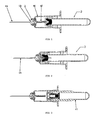
- figure 1 illustrates a housing 46 having an open rear end through which a conventional evacuated blood collection container 2 can pass, this container being similar to that illustrated in the second embodiment.
- the front of housing 46 contains a needle holder assembly, which in this particular embodiment comprises two separate parts being an inner needle holder 1B and an outer nosepiece 2 (see figure 6A ).
- a double ended steel puncture needle 1A extends through the inner needle holder 1B and into the interior of housing 46, this being not dissimilar to that described with reference to the second embodiment.
- the part of the puncture needle 1A that extends in housing 46 is covered by a protective flexible sheath 45 to keep the needle sterile until just before use.
- Figure 1 illustrates the blood collection container 2 pushed into the open rear end of housing 46 and almost in engagement with the rear of needle 1A.
- Figure 2 illustrates further forward movement of the blood collection container 2 which has now been pushed against needle 1A with sufficient force to cause needle 1A to pass through the sealing bung on the forward end of container 2.
- the vacuum within container 2 will now cause blood or other body fluid to be sucked through needle 1A and into container 2.
- the arrangement also causes the protective sheath 45 to be pushed away to expose needle 1A, and this protective sheath is accommodated within an enlargement in the bung, this being illustrated in figure 2 .
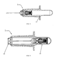
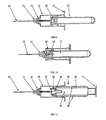
- FIGS 3-5 illustrate a needle retraction device 47 in operation.
- the needle retraction device 47 is a separate member that is pushed into the rear of housing 46 after the blood collection container 2 has been filled and removed from the housing 46.
- the needle retraction device 47 is somewhat similar to that described in the second embodiment and again comprises an elongate body which is hollow and which is under vacuum.
- the front of device 47 contains a piston assembly that can be coupled with the nosepiece 2 to retract the nosepiece and therefore the attached needle 1 A back into the safety of the interior of the needle retraction device 47.
- the needle retraction device 47 has been inserted into housing 46 and is being pushed forwardly towards the contaminated needle 1A.
- the needle retraction device 47 has been pushed against the rear of the nosepiece 2 and is in the process of decoupling the nosepiece from the front of housing 46 (as will be described in greater detail below).
- the needle retraction device has retracted the nosepiece containing the attached needle holder 1B and the attached needle 1A back into the interior of the device by the action of the vacuum in the device as will be described in greater detail below.
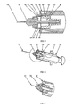
- FIG 6A shows in greater detail the decoupling action and particularly illustrates the front of the needle retraction device 47 just before the point where the needle retraction device 47 decouples nosepiece 2.
- housing 46 is moulded with an internal ramp 3B to assist in the decoupling process.
- the front of housing 46 contains a smaller head portion 48 (see figure 5 ) to contain at least part of nosepiece 2, the needle holder 1B, and the attached puncture needle 1A.
- the needle holding assembly basically comprises three parts being the nosepiece 2, the needle holder 1B, and the puncture needle 1A.
- Nosepiece 2 is an outer member and is substantially hollow to accommodate the needle holder 1B which sits substantially inside nosepiece 2.
- the needle holder 1B contains a conventional internal passageway to accommodate the puncture needle 1A.
- Nosepiece 2 contains a plurality of retaining claws 2B that comprise finger members which are provided with "arrowhead” shaped portions, one portion being on the end of the finger member, and the other portion being positioned intermediate the length of the finger portion.
- the intermediate arrowhead shaped portion abuts against the rear of ramp 3B which forms part of housing 46, and the arrangement prevents the needle holding assembly from being retracted into the housing.
- the intermediate arrow shaped head portion functions to hold the nosepiece, and therefore the entire needle holding assembly from being pushed into housing 46 and from being pulled out of the front of housing 46.
- An anti-spin key 2A is also provided.
- the front of the needle retraction device 47 is open but is closed by a piston assembly having a particular configuration.
- the piston assembly comprises a generally hollow cylindrical piston 5 made of solid (typically plastic) material.
- Piston 5 contains an outer rubber cover that contains a plurality of sealing rings 5B, the function of which is to keep a vacuum tight seal between the piston and the evacuated main body of the needle retraction device 47.
- the outer rubber cover also contains a further outwardly extending ring 5C that grips the inside wall of the needle retraction device and which functions to act as a "brake” or a "speed controller” to control the retraction of the piston into the needle retraction device.
- a further outwardly extending ring 5C that grips the inside wall of the needle retraction device and which functions to act as a "brake” or a "speed controller” to control the retraction of the piston into the needle retraction device.
- the outwardly extending ring 5C functions to slow down the retraction of the piston by increasing the frictional group of the piston against the inside wall of the needle retraction device.
- piston 5 is generally hollow to accommodate the inner end of the (contaminated) puncture needle 1A and the protective sheath 45.
- the inside of piston 5 does contain some soft material 5D that may comprise rubber or something else and that can be pierced by the inner end of the puncture needle 1A. This is illustrated in figure 6A .
- the inner end of the puncture needle has passed into the soft material 5D which functions to plug the needle to prevent blood spray during the retraction process.
- the front of piston 5 contains a plurality of withdrawal claws 2C.
- These claws comprise forwardly extending fingers that contain an arrowhead shaped projection at the end of each finger. It can be seen from figure 6A , that these withdrawal claws 2C also engage against the front of the needle retraction device 47 and therefore lock the piston against retraction into the needle retraction device. Thus, until these withdrawal claws are moved, the piston is locked against retraction.
- the needle retraction device is in the position illustrated in figure 6A where the withdrawal claws 2C are just touching the retaining claws 2B which are on nosepiece 2.
- FIG 6B this illustrates the point of triggering where the piston has been decoupled from the needle retraction device and can now be sucked back by the vacuum in the needle retraction device, and the nosepiece has been decoupled from the front of housing 46 and has been attached to piston 5 such that retraction of the piston also causes retraction of the nosepiece and thus the attached contaminated puncture needle 1A.
- the withdrawal claws 2C engage against the arrowhead projection on the end of each retaining claw 2B and start to push the retaining claw inwardly.
- This action causes the intermediate projection on the retaining claw 2B to disengage against abutment against the housing 46, and also causes the intermediate projection to exit the nosepiece retaining groove 3A.
- the nosepiece 2 becomes free from engagement against housing 46.
- the withdrawal claws 2C on the piston ride up the ramp 3B which forms part of housing 46 and in doing so, the claws are pushed inwardly and therefore no longer engage with the front of the needle retraction device 47.
- Ramp 3B also functions to ensure that the withdrawal claws 2C are properly locked against the retaining claws 2B.
- the arrangement is that piston 5 becomes freed from the needle retraction device 47, nosepiece 2 becomes freed from engagement against housing 46, and the piston 5 locks against nosepiece 2.
- the vacuum within the needle retraction device 47 now functions to suck back the piston 5 into the rear of the device, this being best illustrated in figure 5 .
- the contaminated needle is now perfectly safe.
- FIG. 7A-C there is illustrated a locking arrangement to temporarily lock the vacuum tube (blood collection container 2) to the housing 46.
- the housing 46 contains a locking groove 3C, that accommodates a locking claw or projection 4A on the outside wall of the vacuum tube.
Landscapes
- Health & Medical Sciences (AREA)
- Life Sciences & Earth Sciences (AREA)
- Heart & Thoracic Surgery (AREA)
- Medical Informatics (AREA)
- Biophysics (AREA)
- Pathology (AREA)
- Engineering & Computer Science (AREA)
- Biomedical Technology (AREA)
- Hematology (AREA)
- Physics & Mathematics (AREA)
- Molecular Biology (AREA)
- Surgery (AREA)
- Animal Behavior & Ethology (AREA)
- General Health & Medical Sciences (AREA)
- Public Health (AREA)
- Veterinary Medicine (AREA)
- Measurement Of The Respiration, Hearing Ability, Form, And Blood Characteristics Of Living Organisms (AREA)
Claims (9)
- Dispositif de prélèvement sanguin comprenant un boîtier (10) qui présente une extrémité arrière ouverte apte à loger un tube de prélèvement sanguin sous vide, et une extrémité avant, un porte-aiguille (11) dans l'extrémité avant, une aiguille (12) qui est fixée au porte-aiguille (11) et qui est double, avec une première extrémité extérieure qui dépasse du boîtier (10), et une seconde extrémité intérieure qui dépasse dans le boîtier, le porte-aiguille (11) étant fixé de manière amovible par rapport au boîtier (10) afin de permettre la rétraction du porte-aiguille (11) et de l'aiguille (12) fixée, caractérisé en ce que le porte-aiguille (11) contient au moins un élément saillant qui s'emboîte par rapport au boîtier (10) afin de retenir dans celui-ci le porte-aiguille (11), l'élément saillant étant mobile entre une position de verrouillage dans laquelle il retient le porte-aiguille (11) sur le boîtier (10), et une position de déblocage dans laquelle le porte-aiguille (11) est apte à être rétracté dans le boîtier (10).
- Dispositif tel qu'il est revendiqué dans la revendication 1, comprenant également un dispositif de rétraction d'aiguille, le dispositif de rétraction d'aiguille étant apte à être poussé dans le boîtier afin de débloquer le porte-aiguille par rapport audit boîtier, et à rétracter dans le dispositif de rétraction d'aiguille le porte-aiguille contenant l'aiguille fixée.
- Dispositif tel qu'il est revendiqué dans la revendication 2, étant précisé que le porte-aiguille comprend un ensemble d'au moins deux parties, la première partie étant une partie intérieure et contenant un passage à travers lequel une aiguille de ponction peut s'étendre pour le montage de ladite aiguille de ponction sur la partie intérieure, et la seconde partie comprenant un embout extérieur, le ou les éléments saillants étant fixés par rapport à l'embout.
- Dispositif tel qu'il est revendiqué dans la revendication 3, étant précisé que le dispositif de rétraction d'aiguille comprend un corps creux allongé qui contient un vide et qui a une extrémité ouverte, un piston qui obture l'extrémité ouverte du corps creux allongé et qui est apte à coulisser à l'intérieur du corps creux et qui est fixé de manière amovible par rapport à l'extrémité ouverte.
- Dispositif tel qu'il est revendiqué dans la revendication 4, étant précisé que le piston comprend au moins un élément saillant qui fixe de manière amovible le piston par rapport à une extrémité du corps creux, l'élément saillant étant mobile entre une position de verrouillage dans laquelle le piston est fixé au corps creux, et une position de déblocage dans laquelle le piston est apte à être rétracté dans le corps creux sous l'influence du vide.
- Dispositif tel qu'il est revendiqué dans la revendication 5, étant précisé que le ou les éléments saillants sur le piston s'étendent vers l'avant, à partir du piston, et que le ou les éléments saillants sur le porte-aiguille s'étendent vers l'arrière de telle sorte que le dispositif de rétraction d'aiguille est poussé contre l'arrière du porte-aiguille, que le ou les éléments saillants sur le piston débloquent le ou les éléments saillants sur le porte-aiguille et s'emboîtent avec le ou les éléments saillants sur le porte-aiguille.
- Dispositif tel qu'il est revendiqué dans la revendication 6, étant précisé que le boîtier est pourvu d'une rampe, dans une partie avant, la rampe venant en contact avec le ou les éléments saillants sur le piston quand le dispositif de rétraction d'aiguille est poussé contre l'arrière du porte-aiguille, le ou les éléments saillants glissant le long de la rampe pour débloquer l'emboîtement du ou des éléments saillants avec le corps creux afin de permettre au piston contenant le porte-aiguille fixé d'être rétracté dans le corps creux sous l'influence du vide.
- Dispositif tel qu'il est revendiqué dans la revendication 7, étant précisé que le piston contient un matériau apte à être percé, qui est percé par l'extrémité intérieure de l'aiguille quand le dispositif de rétraction d'aiguille est poussé contre l'arrière du porte-aiguille pour fermer hermétiquement l'extrémité intérieure de l'aiguille.
- Dispositif tel qu'il est revendiqué dans la revendication 8, étant précisé que le piston contient un mécanisme de commande de vitesse pour commander la vitesse de rétraction du piston dans le corps creux, le mécanisme de commande de vitesse comprenant un élément d'étanchéité qui s'étend à partir du piston et qui s'emboîte de manière étanche avec le corps creux pour augmenter la force de friction du piston sur le corps creux.
Priority Applications (3)
| Application Number | Priority Date | Filing Date | Title |
|---|---|---|---|
| SI200531836T SI1706032T1 (sl) | 2004-01-23 | 2005-01-21 | Izboljšave pri napravi za zbiranje krvi |
| PL05700095T PL1706032T3 (pl) | 2004-01-23 | 2005-01-21 | Udoskonalenia w urządzeniu do pobierania krwi |
| CY20141100253T CY1115443T1 (el) | 2004-01-23 | 2014-04-03 | Βελτιωσεις σε μια διαταξη αιμοληψιας |
Applications Claiming Priority (2)
| Application Number | Priority Date | Filing Date | Title |
|---|---|---|---|
| AU2004900310A AU2004900310A0 (en) | 2004-01-23 | Improvements to a Blood Collection Device | |
| PCT/AU2005/000063 WO2005070292A1 (fr) | 2004-01-23 | 2005-01-21 | Ameliorations apportees a un dispositif de prelevement sanguin |
Publications (3)
| Publication Number | Publication Date |
|---|---|
| EP1706032A1 EP1706032A1 (fr) | 2006-10-04 |
| EP1706032A4 EP1706032A4 (fr) | 2007-10-17 |
| EP1706032B1 true EP1706032B1 (fr) | 2014-01-08 |
Family
ID=34800100
Family Applications (1)
| Application Number | Title | Priority Date | Filing Date |
|---|---|---|---|
| EP05700095.2A Expired - Lifetime EP1706032B1 (fr) | 2004-01-23 | 2005-01-21 | Améliorations apportées à un dispositif de prélévement sanguin |
Country Status (11)
| Country | Link |
|---|---|
| US (1) | US7544169B2 (fr) |
| EP (1) | EP1706032B1 (fr) |
| JP (1) | JP4653118B2 (fr) |
| CA (1) | CA2552971C (fr) |
| CY (1) | CY1115443T1 (fr) |
| DK (1) | DK1706032T3 (fr) |
| ES (1) | ES2455996T3 (fr) |
| PL (1) | PL1706032T3 (fr) |
| PT (1) | PT1706032E (fr) |
| SI (1) | SI1706032T1 (fr) |
| WO (1) | WO2005070292A1 (fr) |
Families Citing this family (9)
| Publication number | Priority date | Publication date | Assignee | Title |
|---|---|---|---|---|
| SI1706032T1 (sl) | 2004-01-23 | 2014-07-31 | Medigard Limited | Izboljšave pri napravi za zbiranje krvi |
| BRPI0514909B8 (pt) | 2004-09-03 | 2021-06-22 | L O M Laboratories Inc | seringa de segurança do tipo para uso com uma agulha hipodérmica |
| KR101113752B1 (ko) | 2009-06-23 | 2012-04-13 | 박수희 | 갑상선 조직세포 채취용 주사기 |
| ES2490247T3 (es) * | 2009-10-22 | 2014-09-03 | Medigard Limited | Aguja con visualización de reflujo sanguíneo |
| WO2014172239A1 (fr) * | 2013-04-15 | 2014-10-23 | Becton, Dickinson And Company | Dispositif de collecte de fluide biologique et système de séparation et d'analyse de fluide biologique |
| ES2832756T3 (es) | 2013-04-15 | 2021-06-11 | Becton Dickinson Co | Dispositivo de toma de muestra de fluido biológico |
| US10765815B2 (en) | 2014-10-31 | 2020-09-08 | L.O.M. Laboratories Inc. | Retractable needle syringe |
| CA3012020A1 (fr) | 2015-01-20 | 2016-07-28 | L.O.M. Laboratories Inc. | Seringue a aiguille retractable avec module de liberation de propulseur monobloc |
| CN111957370A (zh) * | 2020-08-11 | 2020-11-20 | 程程 | 一种检验科用器皿端盖取放方法 |
Family Cites Families (95)
| Publication number | Priority date | Publication date | Assignee | Title |
|---|---|---|---|---|
| US4892107A (en) * | 1988-01-05 | 1990-01-09 | Habley Medical Technology Corp. | Single use, safety blood collection device |
| IT1225440B (it) * | 1988-12-07 | 1990-11-13 | Nacci Gaetano | Pistone per siringhe che rende automaticamente inoffensivo l'ago ipodermico, all'uopo modificato, dopo l'uso |
| US5462531A (en) * | 1988-12-14 | 1995-10-31 | Inviro Medical Devices Ltd. | Safety syringe needle device with interchangeable and retractable needle platform |
| CA1337167C (fr) * | 1989-03-14 | 1995-10-03 | Eastman Kodak Company | Gaine avec aiguille retractable |
| US5057087A (en) * | 1989-04-24 | 1991-10-15 | Harmon James E | Hypodermic needle safety system |
| US5578015A (en) * | 1989-09-18 | 1996-11-26 | Robb Pascal Patent Limited | Safety syringe incorporating automatic needle holder release |
| WO1991004065A1 (fr) * | 1989-09-18 | 1991-04-04 | Assumpsit No. 102 Pty. Ltd. | Seringue |
| IT1238143B (it) * | 1990-01-09 | 1993-07-09 | Siringa per iniezioni ipodermiche dotata di stantuffo atto a ritirare e contenere l'ago ipodermico dopo il suo uso | |
| US5000736A (en) * | 1990-03-22 | 1991-03-19 | Harry Kaufhold, Jr. | Disposable syringe with automatic needle retraction |
| US5125898A (en) * | 1990-03-22 | 1992-06-30 | Harry Kaufhold, Jr. | Disposable syringe with automatic needle retraction |
| US5057079A (en) * | 1990-04-03 | 1991-10-15 | Roland Tiemann | Sheathing device for after use protection from a syringe needle |
| US5070885A (en) * | 1990-06-11 | 1991-12-10 | Care Medical Devices, Inc. | Disposable blood collection device |
| US5820605A (en) * | 1990-10-04 | 1998-10-13 | Zdeb; Brian D. | Retractable syringe |
| WO1992018186A1 (fr) * | 1991-04-17 | 1992-10-29 | Louis Ryles | Seringue |
| US5254100A (en) * | 1991-06-06 | 1993-10-19 | Huband Michael L | Protective needle assembly for hypodermic syringe |
| US5263934A (en) * | 1991-11-28 | 1993-11-23 | Haak Abraham Van Den | Stroke limiting syringe with retractable needle |
| US5211629A (en) * | 1991-12-23 | 1993-05-18 | Pressly William B S | Safety syringe |
| US5201708A (en) * | 1992-02-03 | 1993-04-13 | Timothy A. Kershenstine | Self-locking safety syringe |
| US5180370A (en) * | 1992-05-18 | 1993-01-19 | Gillespie Elgene R | Safety hypodermic syringe with retractable needle |
| US5209739A (en) * | 1992-06-23 | 1993-05-11 | Leon Talalay | Hypodermic needle |
| US5531694A (en) * | 1993-08-31 | 1996-07-02 | Clemens; Anton H. | Needle retraction system |
| US5498244A (en) * | 1993-09-22 | 1996-03-12 | American Home Products Corporation | Safety guard for medical instruments |
| US5346475A (en) * | 1993-10-27 | 1994-09-13 | Edward Gregorio | Single use syringe |
| US5423758A (en) * | 1993-12-16 | 1995-06-13 | Shaw; Thomas J. | Retractable fluid collection device |
| US5352203A (en) * | 1994-03-31 | 1994-10-04 | Vallelunga Anthony J | Aspirating non-reuseable syringe |
| US5480385A (en) * | 1995-01-10 | 1996-01-02 | Specialized Health Products, Inc. | Self retracting medical needle apparatus and methods |
| US5562103A (en) * | 1995-04-04 | 1996-10-08 | Sak; Robert F. | Phlebotomy system having retractable needle cannula |
| US5562625A (en) * | 1995-05-02 | 1996-10-08 | Stefancin, Jr.; Ronald J. | Reusasble syringe with a disposable needle sheath |
| IN189105B (fr) * | 1996-05-03 | 2002-12-21 | Nordway Ltd | |
| US6004278A (en) * | 1996-12-05 | 1999-12-21 | Mdc Investment Holdings, Inc. | Fluid collection device with retractable needle |
| US5891104A (en) * | 1997-01-10 | 1999-04-06 | Univec, Inc. | Hypodermic syringe having retractable needle |
| US5868713A (en) * | 1997-04-03 | 1999-02-09 | L.O.M. Laboratories Inc. | Pneumatic retractable syringe |
| US5810775A (en) * | 1997-05-23 | 1998-09-22 | Shaw; Thomas J. | Cap operated retractable medical device |
| BR9814966B1 (pt) * | 1997-11-12 | 2011-01-11 | dispositivo médico. | |
| KR100293809B1 (ko) * | 1998-05-29 | 2001-10-26 | 박종섭 | 다중도메인을갖는아이피에스-브이에이모드액정표시장치 |
| GB2341804B (en) | 1998-09-25 | 2003-02-12 | David William Parker | Improvements in or relating to hypodermic syringes |
| US6210375B1 (en) * | 1998-09-30 | 2001-04-03 | Becton, Dickinson And Company | Needle retraction mechanism with controlled retraction speed |
| US6186960B1 (en) | 1998-10-20 | 2001-02-13 | Texas Applied Biomedical Services, Inc. | Disposable medical collection tube holder with retractable needle |
| US6077245A (en) * | 1999-02-18 | 2000-06-20 | Texas Applied Biomedical Services, Inc. | Disposable syringe with retractable needle |
| FR2794650B1 (fr) | 1999-06-10 | 2001-09-14 | Marc Brunel | Dispositif d'injection a usage unique |
| CA2278390C (fr) * | 1999-07-19 | 2003-10-07 | Yu-Hau Chang-Lai | Seringue de securite |
| US6413236B1 (en) * | 1999-10-08 | 2002-07-02 | Lewis R. Van Dyke | Automatically retractable needle safety syringe |
| US6537257B1 (en) | 1999-11-01 | 2003-03-25 | Abraham Wien | Syringe with reciprocating, leak-proof needle guard |
| WO2001045776A1 (fr) * | 1999-12-07 | 2001-06-28 | Mdc Investment Holdings, Inc. | Dispositifs medicaux comprenant une aiguille de securite retractable |
| US6193695B1 (en) * | 2000-01-14 | 2001-02-27 | Wayland J. Rippstein, Jr. | Disposable safety syringe having a retractable needle |
| AU723060B3 (en) * | 2000-02-22 | 2000-08-17 | Occupational & Medical Innovations Ltd | A single use syringe |
| US6471677B2 (en) * | 2000-04-06 | 2002-10-29 | Gem Plastics, Inc. | Fluid collection device with protective shield |
| TW483767B (en) | 2000-11-08 | 2002-04-21 | Bi-Jang Luo | Safe injector with needle seat of easy fastening |
| US20020173750A1 (en) | 2001-05-18 | 2002-11-21 | Chiu-Yueh Huang | Syringe device |
| US6572565B2 (en) * | 2001-10-10 | 2003-06-03 | Maxxon, Inc. | Blood sampling assembly with a retractable needle |
| US6409704B1 (en) | 2001-11-19 | 2002-06-25 | Hsi-Chin Tsai | Retractable safety syringe |
| FR2838971B1 (fr) | 2002-04-25 | 2004-07-02 | Plastic Omnium Cie | Ensemble de seringue d'injection de liquide et fourreau pour cet ensemble |
| US20030212371A1 (en) | 2002-05-10 | 2003-11-13 | Martin E. Smith | Disposable safety syringe |
| TW572761B (en) * | 2002-07-17 | 2004-01-21 | Ming-Jeng Shiu | Syringe with retraction force |
| US6911018B2 (en) | 2002-08-06 | 2005-06-28 | Cosmetic And Medical Inventions, Llc | Safety syringe |
| EP1551483B1 (fr) | 2002-09-25 | 2007-01-10 | Becton, Dickinson and Company | Seringue a usage unique pour operations en deux temps |
| NL1021689C2 (nl) | 2002-10-18 | 2004-05-12 | Advanced Protective Injection | Injectiespuit met terugtrekbare inspuitnaald. |
| US6846301B2 (en) * | 2002-11-01 | 2005-01-25 | Maxxon, Inc. | Disposable safety syringe |
| US20040153035A1 (en) | 2002-11-22 | 2004-08-05 | Life-Shield Products Inc. | Retractable type safety syringe |
| TW586947B (en) * | 2002-12-02 | 2004-05-11 | Ming-Jeng Shiu | Safety device for injection and blood-drawing |
| AR043668A1 (es) | 2003-03-20 | 2005-08-03 | Unitract Syringe Pty Ltd | Reten de resorte para jeringa |
| US20040210198A1 (en) | 2003-04-18 | 2004-10-21 | Life-Shield Products, Inc. | Safety retractable type syringe |
| US7179243B2 (en) | 2003-05-09 | 2007-02-20 | Cho Ying Chen | Syringe with a snapping device for backward pulling the needle into the syringe after syringing |
| GB0312852D0 (en) | 2003-06-05 | 2003-07-09 | Owen Mumford Ltd | Improvements relating to syringe firing mechanisms |
| TWI224516B (en) | 2003-06-16 | 2004-12-01 | Shu-Chen Chou | Destructible safety syringe and barrel thereof |
| US7331934B2 (en) | 2003-07-30 | 2008-02-19 | Becton Dickinson Co | Syringe assembly having disabling mechanism |
| US20050080380A1 (en) | 2003-10-14 | 2005-04-14 | Hsin-Po Hsieh | Safety syringe |
| JP2007514486A (ja) | 2003-12-18 | 2007-06-07 | ブルーアー・リトラクタブル・テクノロジーズ・プロプライエタリー・リミテッド | 皮下注射器 |
| SI1706032T1 (sl) | 2004-01-23 | 2014-07-31 | Medigard Limited | Izboljšave pri napravi za zbiranje krvi |
| EP1708772B1 (fr) | 2004-01-28 | 2012-06-20 | Unitract Syringe Pty Ltd | Seringue retractable a systeme de desactivation du piston |
| US7189216B2 (en) | 2004-02-27 | 2007-03-13 | Vantex Biotechnology Co., Ltd. | Coupling structure for self-destruction and safety syringe |
| TWI256900B (en) | 2004-04-30 | 2006-06-21 | Ming-Jeng Shiu | Syringe with withdrawal force |
| US20070250004A1 (en) | 2004-07-08 | 2007-10-25 | Chung-Hao Tung | Safe syringe with automatically retractable needle |
| MX2007001726A (es) | 2004-08-13 | 2007-04-20 | Becton Dickinson Co | Ensamblaje de jeringa con aguja retractil. |
| US20080161760A1 (en) | 2004-08-20 | 2008-07-03 | Medigard Limited | Medical Device Containing a Vacuum Chamber |
| BRPI0514909B8 (pt) | 2004-09-03 | 2021-06-22 | L O M Laboratories Inc | seringa de segurança do tipo para uso com uma agulha hipodérmica |
| US20060106341A1 (en) | 2004-09-16 | 2006-05-18 | Jin-Rong Lou | Safety syringe having retraction mechanism |
| US20060084918A1 (en) | 2004-10-15 | 2006-04-20 | Intai Technology Inc. | Retractable safety syringe |
| US7381199B2 (en) * | 2004-11-09 | 2008-06-03 | Kuo-Lung Kuan | Structure of safety hypodermic syringe |
| ITBS20040143A1 (it) | 2004-11-24 | 2005-02-24 | Iisidoro Mazzara | Siringa di sicurezza perfezionata ad ago retrattile |
| JP4738420B2 (ja) | 2004-12-21 | 2011-08-03 | ベクトン・ディキンソン・アンド・カンパニー | 不能化機構を有する注射器アセンブリ |
| US7637890B2 (en) | 2005-01-25 | 2009-12-29 | Zuoqian Lin | Safety self-destroying disposable syringe |
| US20060229555A1 (en) | 2005-04-11 | 2006-10-12 | Wei-Shui Wu | Safety syringe with a needle seat |
| US7947020B2 (en) | 2005-05-09 | 2011-05-24 | Safeshot Technologies, Llc | Retractable safety syringe |
| TWI268786B (en) | 2005-06-13 | 2006-12-21 | Ming-Jeng Shiu | Injector having drawing back force |
| US20070060886A1 (en) | 2005-08-25 | 2007-03-15 | Knepshield William R | Syringe |
| US7762987B2 (en) | 2005-08-26 | 2010-07-27 | Wei-Shui Wu | Safety syringe device with separable needle stem by turning back |
| US7931617B2 (en) | 2006-02-08 | 2011-04-26 | Feng-Hui Lu | Safety syringe |
| US8152762B2 (en) | 2006-04-20 | 2012-04-10 | Safeshot Technologies, Llc | Plunger activated vacuum release mechanism for a syringe |
| US20080097303A1 (en) | 2006-06-02 | 2008-04-24 | Chih-Hsiung Chen | Syringe with retractable needle |
| US20080097305A1 (en) | 2006-08-29 | 2008-04-24 | Jin-Chou Tsai | Safety hypodermic syringe |
| US7611488B2 (en) | 2006-12-20 | 2009-11-03 | Komas Chang | Safety hypodermic syringe |
| US20080154194A1 (en) | 2006-12-21 | 2008-06-26 | Hung-Chi Huang | Safety syringe device with retractable needle cannula |
| US20080154195A1 (en) | 2006-12-21 | 2008-06-26 | Hung-Chi Huang | Safety syringe device |
| CN101020090B (zh) | 2007-03-30 | 2012-01-04 | 刘文杰 | 一种改进的针头回缩式安全注射器筒式推杆及注射器 |
-
2005
- 2005-01-21 SI SI200531836T patent/SI1706032T1/sl unknown
- 2005-01-21 PL PL05700095T patent/PL1706032T3/pl unknown
- 2005-01-21 US US10/587,139 patent/US7544169B2/en not_active Expired - Lifetime
- 2005-01-21 WO PCT/AU2005/000063 patent/WO2005070292A1/fr not_active Ceased
- 2005-01-21 CA CA2552971A patent/CA2552971C/fr not_active Expired - Lifetime
- 2005-01-21 DK DK05700095.2T patent/DK1706032T3/da active
- 2005-01-21 EP EP05700095.2A patent/EP1706032B1/fr not_active Expired - Lifetime
- 2005-01-21 JP JP2006549781A patent/JP4653118B2/ja not_active Expired - Fee Related
- 2005-01-21 ES ES05700095.2T patent/ES2455996T3/es not_active Expired - Lifetime
- 2005-01-21 PT PT57000952T patent/PT1706032E/pt unknown
-
2014
- 2014-04-03 CY CY20141100253T patent/CY1115443T1/el unknown
Also Published As
| Publication number | Publication date |
|---|---|
| ES2455996T3 (es) | 2014-04-21 |
| DK1706032T3 (da) | 2014-03-31 |
| CA2552971A1 (fr) | 2005-08-04 |
| US7544169B2 (en) | 2009-06-09 |
| JP2007518495A (ja) | 2007-07-12 |
| PL1706032T3 (pl) | 2014-07-31 |
| SI1706032T1 (sl) | 2014-07-31 |
| EP1706032A1 (fr) | 2006-10-04 |
| JP4653118B2 (ja) | 2011-03-16 |
| PT1706032E (pt) | 2014-04-14 |
| EP1706032A4 (fr) | 2007-10-17 |
| US20070265549A1 (en) | 2007-11-15 |
| WO2005070292A1 (fr) | 2005-08-04 |
| CY1115443T1 (el) | 2017-01-04 |
| CA2552971C (fr) | 2013-08-20 |
Similar Documents
| Publication | Publication Date | Title |
|---|---|---|
| US11679233B2 (en) | Retractable needle catheter insertion device | |
| US6096005A (en) | Retractable needle medical devices | |
| US5415648A (en) | Multiple purpose syringe | |
| US5658257A (en) | Syringe | |
| US5562626A (en) | Safety syringe | |
| US5188599A (en) | Retractable needle system | |
| US4994034A (en) | Retractable needle hypodermic syringe system | |
| EP1433419B1 (fr) | Aiguille de sécurité avec protecteur pivotable | |
| US20030023205A1 (en) | Medical devices with retractable needle | |
| US6379338B1 (en) | Retracting tip for catheter set | |
| CA2409297C (fr) | Combinaison d'une seringue et d'une aiguille retractable | |
| CA2552971C (fr) | Ameliorations apportees a un dispositif de prelevement sanguin | |
| US6186960B1 (en) | Disposable medical collection tube holder with retractable needle | |
| US20070073237A1 (en) | Cannula/catheter introducer | |
| US20080154213A1 (en) | Syringe with multiple plunger locks | |
| US6767335B1 (en) | Syringe of single-use type intended for injection or lab tests | |
| AU2005207079B2 (en) | Improvements to a blood collection device | |
| JP4722365B2 (ja) | 安全有針医療用装置 | |
| EP0962230B1 (fr) | Dispositif d'aiguille, en particulier aiguille hypodermique | |
| AU1983992A (en) | A syringe |
Legal Events
| Date | Code | Title | Description |
|---|---|---|---|
| PUAI | Public reference made under article 153(3) epc to a published international application that has entered the european phase |
Free format text: ORIGINAL CODE: 0009012 |
|
| 17P | Request for examination filed |
Effective date: 20060721 |
|
| AK | Designated contracting states |
Kind code of ref document: A1 Designated state(s): AT BE BG CH CY CZ DE DK EE ES FI FR GB GR HU IE IS IT LI LT LU MC NL PL PT RO SE SI SK TR |
|
| DAX | Request for extension of the european patent (deleted) | ||
| A4 | Supplementary search report drawn up and despatched |
Effective date: 20070913 |
|
| 17Q | First examination report despatched |
Effective date: 20130228 |
|
| GRAP | Despatch of communication of intention to grant a patent |
Free format text: ORIGINAL CODE: EPIDOSNIGR1 |
|
| INTG | Intention to grant announced |
Effective date: 20130816 |
|
| GRAS | Grant fee paid |
Free format text: ORIGINAL CODE: EPIDOSNIGR3 |
|
| GRAA | (expected) grant |
Free format text: ORIGINAL CODE: 0009210 |
|
| AK | Designated contracting states |
Kind code of ref document: B1 Designated state(s): AT BE BG CH CY CZ DE DK EE ES FI FR GB GR HU IE IS IT LI LT LU MC NL PL PT RO SE SI SK TR |
|
| REG | Reference to a national code |
Ref country code: GB Ref legal event code: FG4D |
|
| REG | Reference to a national code |
Ref country code: CH Ref legal event code: EP |
|
| REG | Reference to a national code |
Ref country code: IE Ref legal event code: FG4D |
|
| REG | Reference to a national code |
Ref country code: AT Ref legal event code: REF Ref document number: 648154 Country of ref document: AT Kind code of ref document: T Effective date: 20140215 |
|
| REG | Reference to a national code |
Ref country code: DE Ref legal event code: R096 Ref document number: 602005042411 Country of ref document: DE Effective date: 20140220 |
|
| REG | Reference to a national code |
Ref country code: RO Ref legal event code: EPE |
|
| REG | Reference to a national code |
Ref country code: DK Ref legal event code: T3 Effective date: 20140327 |
|
| REG | Reference to a national code |
Ref country code: PT Ref legal event code: SC4A Free format text: AVAILABILITY OF NATIONAL TRANSLATION Effective date: 20140404 |
|
| REG | Reference to a national code |
Ref country code: NL Ref legal event code: T3 |
|
| REG | Reference to a national code |
Ref country code: ES Ref legal event code: FG2A Ref document number: 2455996 Country of ref document: ES Kind code of ref document: T3 Effective date: 20140421 |
|
| REG | Reference to a national code |
Ref country code: SE Ref legal event code: TRGR |
|
| REG | Reference to a national code |
Ref country code: GR Ref legal event code: EP Ref document number: 20140400651 Country of ref document: GR Effective date: 20140515 |
|
| REG | Reference to a national code |
Ref country code: SK Ref legal event code: T3 Ref document number: E 16104 Country of ref document: SK |
|
| REG | Reference to a national code |
Ref country code: PL Ref legal event code: T3 |
|
| REG | Reference to a national code |
Ref country code: HU Ref legal event code: AG4A Ref document number: E020035 Country of ref document: HU |
|
| REG | Reference to a national code |
Ref country code: DE Ref legal event code: R097 Ref document number: 602005042411 Country of ref document: DE |
|
| PG25 | Lapsed in a contracting state [announced via postgrant information from national office to epo] |
Ref country code: MC Free format text: LAPSE BECAUSE OF FAILURE TO SUBMIT A TRANSLATION OF THE DESCRIPTION OR TO PAY THE FEE WITHIN THE PRESCRIBED TIME-LIMIT Effective date: 20140108 Ref country code: EE Free format text: LAPSE BECAUSE OF FAILURE TO SUBMIT A TRANSLATION OF THE DESCRIPTION OR TO PAY THE FEE WITHIN THE PRESCRIBED TIME-LIMIT Effective date: 20140108 |
|
| PLBE | No opposition filed within time limit |
Free format text: ORIGINAL CODE: 0009261 |
|
| STAA | Information on the status of an ep patent application or granted ep patent |
Free format text: STATUS: NO OPPOSITION FILED WITHIN TIME LIMIT |
|
| 26N | No opposition filed |
Effective date: 20141009 |
|
| REG | Reference to a national code |
Ref country code: DE Ref legal event code: R097 Ref document number: 602005042411 Country of ref document: DE Effective date: 20141009 |
|
| REG | Reference to a national code |
Ref country code: FR Ref legal event code: PLFP Year of fee payment: 12 |
|
| PG25 | Lapsed in a contracting state [announced via postgrant information from national office to epo] |
Ref country code: LU Free format text: LAPSE BECAUSE OF NON-PAYMENT OF DUE FEES Effective date: 20140121 |
|
| REG | Reference to a national code |
Ref country code: FR Ref legal event code: PLFP Year of fee payment: 13 |
|
| REG | Reference to a national code |
Ref country code: FR Ref legal event code: PLFP Year of fee payment: 14 |
|
| PGFP | Annual fee paid to national office [announced via postgrant information from national office to epo] |
Ref country code: IS Payment date: 20190123 Year of fee payment: 15 |
|
| PGFP | Annual fee paid to national office [announced via postgrant information from national office to epo] |
Ref country code: GR Payment date: 20190122 Year of fee payment: 15 |
|
| PGFP | Annual fee paid to national office [announced via postgrant information from national office to epo] |
Ref country code: SK Payment date: 20190117 Year of fee payment: 15 |
|
| PGFP | Annual fee paid to national office [announced via postgrant information from national office to epo] |
Ref country code: IE Payment date: 20200109 Year of fee payment: 16 Ref country code: DK Payment date: 20200110 Year of fee payment: 16 Ref country code: PL Payment date: 20200116 Year of fee payment: 16 |
|
| PGFP | Annual fee paid to national office [announced via postgrant information from national office to epo] |
Ref country code: BE Payment date: 20200114 Year of fee payment: 16 Ref country code: CH Payment date: 20200116 Year of fee payment: 16 |
|
| PGFP | Annual fee paid to national office [announced via postgrant information from national office to epo] |
Ref country code: TR Payment date: 20200121 Year of fee payment: 16 |
|
| REG | Reference to a national code |
Ref country code: SK Ref legal event code: MM4A Ref document number: E 16104 Country of ref document: SK Effective date: 20200121 |
|
| REG | Reference to a national code |
Ref country code: LT Ref legal event code: MM4D Effective date: 20200121 |
|
| PG25 | Lapsed in a contracting state [announced via postgrant information from national office to epo] |
Ref country code: RO Free format text: LAPSE BECAUSE OF NON-PAYMENT OF DUE FEES Effective date: 20200121 Ref country code: CZ Free format text: LAPSE BECAUSE OF NON-PAYMENT OF DUE FEES Effective date: 20200121 Ref country code: GR Free format text: LAPSE BECAUSE OF NON-PAYMENT OF DUE FEES Effective date: 20200806 Ref country code: CY Free format text: LAPSE BECAUSE OF NON-PAYMENT OF DUE FEES Effective date: 20200121 Ref country code: SK Free format text: LAPSE BECAUSE OF NON-PAYMENT OF DUE FEES Effective date: 20200121 |
|
| PG25 | Lapsed in a contracting state [announced via postgrant information from national office to epo] |
Ref country code: HU Free format text: LAPSE BECAUSE OF NON-PAYMENT OF DUE FEES Effective date: 20200122 Ref country code: BG Free format text: LAPSE BECAUSE OF NON-PAYMENT OF DUE FEES Effective date: 20200731 Ref country code: SI Free format text: LAPSE BECAUSE OF NON-PAYMENT OF DUE FEES Effective date: 20200122 |
|
| PG25 | Lapsed in a contracting state [announced via postgrant information from national office to epo] |
Ref country code: LT Free format text: LAPSE BECAUSE OF NON-PAYMENT OF DUE FEES Effective date: 20200121 |
|
| PGFP | Annual fee paid to national office [announced via postgrant information from national office to epo] |
Ref country code: IT Payment date: 20210126 Year of fee payment: 17 Ref country code: FI Payment date: 20210125 Year of fee payment: 17 Ref country code: NL Payment date: 20210125 Year of fee payment: 17 Ref country code: PT Payment date: 20210118 Year of fee payment: 17 |
|
| PGFP | Annual fee paid to national office [announced via postgrant information from national office to epo] |
Ref country code: ES Payment date: 20210205 Year of fee payment: 17 Ref country code: AT Payment date: 20210125 Year of fee payment: 17 |
|
| REG | Reference to a national code |
Ref country code: DK Ref legal event code: EBP Effective date: 20210131 |
|
| REG | Reference to a national code |
Ref country code: CH Ref legal event code: PL |
|
| REG | Reference to a national code |
Ref country code: BE Ref legal event code: MM Effective date: 20210131 |
|
| PG25 | Lapsed in a contracting state [announced via postgrant information from national office to epo] |
Ref country code: LI Free format text: LAPSE BECAUSE OF NON-PAYMENT OF DUE FEES Effective date: 20210131 Ref country code: CH Free format text: LAPSE BECAUSE OF NON-PAYMENT OF DUE FEES Effective date: 20210131 |
|
| PG25 | Lapsed in a contracting state [announced via postgrant information from national office to epo] |
Ref country code: IE Free format text: LAPSE BECAUSE OF NON-PAYMENT OF DUE FEES Effective date: 20210121 Ref country code: DK Free format text: LAPSE BECAUSE OF NON-PAYMENT OF DUE FEES Effective date: 20210131 |
|
| PG25 | Lapsed in a contracting state [announced via postgrant information from national office to epo] |
Ref country code: TR Free format text: LAPSE BECAUSE OF NON-PAYMENT OF DUE FEES Effective date: 20210121 |
|
| PG25 | Lapsed in a contracting state [announced via postgrant information from national office to epo] |
Ref country code: BE Free format text: LAPSE BECAUSE OF NON-PAYMENT OF DUE FEES Effective date: 20210131 |
|
| REG | Reference to a national code |
Ref country code: FI Ref legal event code: MAE |
|
| REG | Reference to a national code |
Ref country code: NL Ref legal event code: MM Effective date: 20220201 |
|
| REG | Reference to a national code |
Ref country code: AT Ref legal event code: MM01 Ref document number: 648154 Country of ref document: AT Kind code of ref document: T Effective date: 20220121 |
|
| PG25 | Lapsed in a contracting state [announced via postgrant information from national office to epo] |
Ref country code: PT Free format text: LAPSE BECAUSE OF NON-PAYMENT OF DUE FEES Effective date: 20220721 Ref country code: NL Free format text: LAPSE BECAUSE OF NON-PAYMENT OF DUE FEES Effective date: 20220201 Ref country code: FI Free format text: LAPSE BECAUSE OF NON-PAYMENT OF DUE FEES Effective date: 20220121 Ref country code: AT Free format text: LAPSE BECAUSE OF NON-PAYMENT OF DUE FEES Effective date: 20220121 |
|
| PG25 | Lapsed in a contracting state [announced via postgrant information from national office to epo] |
Ref country code: IT Free format text: LAPSE BECAUSE OF NON-PAYMENT OF DUE FEES Effective date: 20220121 |
|
| PGFP | Annual fee paid to national office [announced via postgrant information from national office to epo] |
Ref country code: SE Payment date: 20221110 Year of fee payment: 19 Ref country code: GB Payment date: 20221201 Year of fee payment: 19 Ref country code: FR Payment date: 20221208 Year of fee payment: 19 |
|
| PG25 | Lapsed in a contracting state [announced via postgrant information from national office to epo] |
Ref country code: PL Free format text: LAPSE BECAUSE OF NON-PAYMENT OF DUE FEES Effective date: 20210121 |
|
| REG | Reference to a national code |
Ref country code: ES Ref legal event code: FD2A Effective date: 20230301 |
|
| PG25 | Lapsed in a contracting state [announced via postgrant information from national office to epo] |
Ref country code: ES Free format text: LAPSE BECAUSE OF NON-PAYMENT OF DUE FEES Effective date: 20220122 |
|
| PGFP | Annual fee paid to national office [announced via postgrant information from national office to epo] |
Ref country code: DE Payment date: 20221130 Year of fee payment: 19 |
|
| REG | Reference to a national code |
Ref country code: DE Ref legal event code: R119 Ref document number: 602005042411 Country of ref document: DE |
|
| REG | Reference to a national code |
Ref country code: SE Ref legal event code: EUG |
|
| GBPC | Gb: european patent ceased through non-payment of renewal fee |
Effective date: 20240121 |
|
| PG25 | Lapsed in a contracting state [announced via postgrant information from national office to epo] |
Ref country code: DE Free format text: LAPSE BECAUSE OF NON-PAYMENT OF DUE FEES Effective date: 20240801 |
|
| PG25 | Lapsed in a contracting state [announced via postgrant information from national office to epo] |
Ref country code: GB Free format text: LAPSE BECAUSE OF NON-PAYMENT OF DUE FEES Effective date: 20240121 |
|
| PG25 | Lapsed in a contracting state [announced via postgrant information from national office to epo] |
Ref country code: FR Free format text: LAPSE BECAUSE OF NON-PAYMENT OF DUE FEES Effective date: 20240131 |
|
| PG25 | Lapsed in a contracting state [announced via postgrant information from national office to epo] |
Ref country code: GB Free format text: LAPSE BECAUSE OF NON-PAYMENT OF DUE FEES Effective date: 20240121 Ref country code: FR Free format text: LAPSE BECAUSE OF NON-PAYMENT OF DUE FEES Effective date: 20240131 Ref country code: DE Free format text: LAPSE BECAUSE OF NON-PAYMENT OF DUE FEES Effective date: 20240801 |
|
| PG25 | Lapsed in a contracting state [announced via postgrant information from national office to epo] |
Ref country code: SE Free format text: LAPSE BECAUSE OF NON-PAYMENT OF DUE FEES Effective date: 20240122 |
|
| PG25 | Lapsed in a contracting state [announced via postgrant information from national office to epo] |
Ref country code: IS Free format text: LAPSE BECAUSE OF NON-PAYMENT OF DUE FEES Effective date: 20200806 |