EP1706246B1 - Spaltmaschine - Google Patents
Spaltmaschine Download PDFInfo
- Publication number
- EP1706246B1 EP1706246B1 EP04801237A EP04801237A EP1706246B1 EP 1706246 B1 EP1706246 B1 EP 1706246B1 EP 04801237 A EP04801237 A EP 04801237A EP 04801237 A EP04801237 A EP 04801237A EP 1706246 B1 EP1706246 B1 EP 1706246B1
- Authority
- EP
- European Patent Office
- Prior art keywords
- splitting
- wood
- station
- cutting
- piece
- Prior art date
- Legal status (The legal status is an assumption and is not a legal conclusion. Google has not performed a legal analysis and makes no representation as to the accuracy of the status listed.)
- Expired - Lifetime
Links
- 239000002023 wood Substances 0.000 claims abstract description 71
- 230000033001 locomotion Effects 0.000 claims description 11
- 239000002184 metal Substances 0.000 claims description 4
- 210000000056 organ Anatomy 0.000 claims description 4
- 230000008878 coupling Effects 0.000 claims description 2
- 238000010168 coupling process Methods 0.000 claims description 2
- 238000005859 coupling reaction Methods 0.000 claims description 2
- 230000005540 biological transmission Effects 0.000 description 4
- 230000005611 electricity Effects 0.000 description 2
- 238000004519 manufacturing process Methods 0.000 description 2
- 238000000034 method Methods 0.000 description 2
- 238000010276 construction Methods 0.000 description 1
- 230000003247 decreasing effect Effects 0.000 description 1
- 230000000704 physical effect Effects 0.000 description 1
Images
Classifications
-
- B—PERFORMING OPERATIONS; TRANSPORTING
- B27—WORKING OR PRESERVING WOOD OR SIMILAR MATERIAL; NAILING OR STAPLING MACHINES IN GENERAL
- B27B—SAWS FOR WOOD OR SIMILAR MATERIAL; COMPONENTS OR ACCESSORIES THEREFOR
- B27B5/00—Sawing machines working with circular or cylindrical saw blades; Components or equipment therefor
- B27B5/16—Saw benches
- B27B5/18—Saw benches with feedable circular saw blade, e.g. arranged on a carriage
- B27B5/185—Saw benches with feedable circular saw blade, e.g. arranged on a carriage the saw blade being carried by a pivoted lever
-
- B—PERFORMING OPERATIONS; TRANSPORTING
- B27—WORKING OR PRESERVING WOOD OR SIMILAR MATERIAL; NAILING OR STAPLING MACHINES IN GENERAL
- B27L—REMOVING BARK OR VESTIGES OF BRANCHES; SPLITTING WOOD; MANUFACTURE OF VENEER, WOODEN STICKS, WOOD SHAVINGS, WOOD FIBRES OR WOOD POWDER
- B27L7/00—Arrangements for splitting wood
Definitions
- the invention relates to a splitting machine, which has a cutting station for cutting a piece of wood of a certain length from a wood to be handled and a splitting station, existing essentially underneath the cutting station, for splitting the piece of wood, being cut and dropped thereto from the cutting station, into two or more parts.
- US-A-4 284 112 discloses a splitting machine in accordance with the preamble of claim 1.
- the length of the pieces of wood to be split is usually about 600 mm, whereby a stroke length of approximately 650 mm for the cylinder is requested.
- the length of chopped wood being sawn today is in most cases 250 - 330 mm and in some cases, depending on the dimensions of the boiler furnaces, approximately 400 - 550 mm.
- the splitting machine according to the present invention is primarily characterized in that it has an adjustment assembly in order to split pieces of wood of essentially deviating lenghts by changing the mutual longitudinal position of the cutting station and the splitting station in respect with each other according to the need at any given time.
- the splitting station of the splitting machine has been arranged as an advantageous embodiment moveable in respect with the cutting station, because in practice very high physical properties are demanded of the shapes of the splitting blade and the splitting groove, the cutting blade and the feed table for wood will stay stationarily in their positions.
- the splitting frame and for example the conveyor for chopped wood existing in connection with the above are made moveable as a whole, the characteristics demanded of the splitting environment remain essentially the same as before.
- Movement of the splitting station may in this context be manual or hydraulic and it can be carried out steplessly or e.g. by four-stepped, e.g. with 300, 350, 550 and 650 mm strokes.
- the length of the stroke must be approximately 50 mm longer than the piece of wood to be split, so that a piece of wood, being cut, may drop freely into the splitting groove.
- the splitting machine according to the invention the working rotation increases significantly so that in other words it gets at least twice as fast than before.
- a circular saw blade is being used, equipped e.g. with hard metal teeth, it is thus possible to take advantage of almost all of the improvement of the operating efficiency being achieved, also for the part of splitting.
- This kind of improvement in the splitting speed by optimizing the length of the stroke increases significantly the work profitability particularly with hydraulic cylinders with a capacity of e.g. five or six tons or more. Since, thanks to the splitting machine according to the invention, it is possible to split woods of deviating lengths significantly faster than before without the need for increase in the power demand of the machinery, this invention has a big cost saving influence particularly thanks to the fact that the electricity connections need not be increased, either.
- the invention relates to a splitting machine, which has a cutting station for cutting a piece of wood of a certain length from a wood 13 to be handled and a splitting station, existing essentially underneath the cutting station, for splitting the piece of wood, being cut and dropped thereto from the cutting station, into two or more parts.
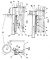
- the splitting machine has an adjustment assembly in order to split pieces of wood of essentially deviating lengths by changing the mutual longitudinal position of the cutting station and the splitting station in respect with each other according to the need at any given time advantageously on the principle shown for example in figures 2 and 3 .
- the splitting machine has a frame 1, wherein the cutting station existing in connection with the same has means for supporting the wood to be handled, such as a support surface, a feed conveyor 3 or a like, means for positioning of the wood to be handled, such as a back stopper 9 and a back guard 10 or the like, and means for cutting the wood, such as a circular saw blade equipped with hard metal teeth 11, a chain saw or the like.
- the splitting station existing in connection with the frame, has correspondingly a frame part 5 that is equipped with a splitting groove, means for splitting a piece of wood, being cut, such as a pusher 4, being arranged moveable in the longitudinal direction by means of a guide rail 7, and a splitting blade arrangement 8 or a like, and organs for operating the splitting means, such as one or several hydraulic cylinders 2 or like.
- the adjustment assembly comprises means for attaching the cutting station and the splitting station with each other in mutually adjustable positions in the longitudinal direction by way of mutual coupling arrangements between the same, such as by guide rails 6, existing in connection with the cutting station, and by guides 12, existing in connection with the splitting station.
- the frame 1 of the splitting machine and at least a part of the cutting station, such as the feed conveyor 3, the back stopper 9, the back guard 10, the guide rails 6 and/or the circular saw blade 11, are arranged as a stationary, non-moveable part of the adjustment assembly, and correspondingly at least a part of the splitting station, such as the frame part 5, the guide rail 7, the pusher 4, the guides 12, the hydraulic cylinder 2 and/or the splitting blade arrangement 8, are arranged as a moveable part of the adjustment assembly.
- the splitting station When splitting longer pieces of wood, the splitting station is, as shown in figure 2 , arranged to be moved further away from the cutting means, such as the circular saw blade 11, in a way that the length of the piece of the wood becomes as desired limited by the positioning means, such as the back stopper 9 or the like.
- the splitting station When splitting shorter pieces of wood, the splitting station is arranged, as shown in figure 3 , to be moved closer to the cutting means, such as the circular saw blade 11, in a way that the length of the piece of the wood becomes as desired limited by the positioning means, such as the back stopper 9 or the like.
- the return movement of the organs, such as the hydraulic cylinder 2 or the like, operating the splitting means is limited automatically for example by mechanical and/or auxiliary powered, such as by electric or hydraulic stroke limiters in a way that the pusher 4 remains during the return movement at a certain distance from the cutting means, such as the circular saw blade 11, and from the back guard 10 of the splitting groove, so that the piece of wood, being cut, may drop down freely.
- a back stopper 9 that belongs to the positioning means is as an advantageous embodiment coupled with the frame 1 for example jointedly in a way that, when the cutting means is in its upper position, the back stopper 9 is in its limiting position, and, when the cutting means 11 is being lowered by means of an auxiliary powered, such as by a hydraulic or a manual feed motion, the back stopper 9 yields automatically backwards, wherein the piece of wood, being cut, may drop down freely.
- a back stopper 9 that belongs to the positioning means may on the other hand be fastened stationarily for example to the frame part 5 of the moveable splitting station, whereby it moves automatically to its respective position of use always, when the splitting station is being moved.
- the splitting function of the splitting station is arranged to start automatically by means of mechanical and/or auxiliary powered, such as by electric and/or hydraulic arrangements, guided by an uplifting motion of the cutting means, such as the circular saw blade 11.
- a conveyor is arranged in connection with the splitting station in order to transport chopped wood away from the splitting machine, which has not, however, been utilized in the embodiment shown in the drawing.
- the operating principle of the splitting machine according to the invention when cutting longer wood products, the length of which is e.g. 600 mm, is as follows:
- the splitting station is being moved first of all to the right, away from the cutting blade 11 in a way that the desired cutting length 600 mm of the back stopper 9, being e.g. moveable along with the cutting station, is achieved.
- the wood is being fed with a feed conveyor 3 to the back stopper 9, whereafter the wood is being cut by the saw 11.
- the wood drops immediately after the cutting into the splitting groove.
- the splitting starts automatically guided by the uplifting movement of the cutting blade 11 either mechanically or electrically.
- the splitting cylinder 2 pushes the wood by means of the pusher 4 against the splitting blade, which may be arranged to split wood in two, four or more parts and which may be as usual vertically adjustable. After the splitting, the woods are being transferred e.g. by means of a chopped wood conveyor away from the splitting machine.
- the operating principle of the splitting machine according to the invention when producing shorter wood products, the length of which being e.g. 300 mm, is as follows:
- the splitting station is being moved towards the cutting blade 11 in a way that the desired cutting length 300 mm limited by the back stopper 9, being e.g. moveable along with the splitting station, is achieved, whereafter the operation proceeds e.g. as explained above.
- the invention is not limited to the applications presented or described above, but it can be modified within the basic idea of the invention as defined in claim 1 according to practical needs and applications at any given time.
- the length of the pieces of wood to be split may be changed e.g. by moving the cutting blade and the feed conveyor or only by moving the splitting blade.
- Significantly more power transmission problems, as well as many kind of practical problems related to the structure of the splitting station, in addition to problems related to control engineering, are, however, involved with the arrangements mentioned above, when compared to the solution presented in the drawing.
Landscapes
- Life Sciences & Earth Sciences (AREA)
- Engineering & Computer Science (AREA)
- Wood Science & Technology (AREA)
- Forests & Forestry (AREA)
- Mechanical Engineering (AREA)
- Debarking, Splitting, And Disintegration Of Timber (AREA)
- Shovels (AREA)
- Transition And Organic Metals Composition Catalysts For Addition Polymerization (AREA)
- Fats And Perfumes (AREA)
Claims (7)
- Eine Spaltmaschine mit einer Schneidestation zum Schneiden eines Holzstücks einer bestimmten Länge von einem zu bearbeitenden Holz (13), einer Spaltstation, die sich im Wesentlichen unterhalb der Schneidestation befindet, zum Spalten des Holzstücks, das von der Schneidestation geschnitten und auf die Spaltstation hinab geworfen wird, in zwei oder mehrere Teile, und einer Einstellvorrichtung, um Holzstücke von im Wesentlichen abweichender Länge zu spalten, wobei die Spaltmaschine einen Rahmen (1) umfasst, in dem die in Verbindung mit derselben existierende Schneidestation Mittel zur Abstützung des zu bearbeitenden Holzes, wie eine Stützfläche oder ein Vorschubförderband (3), Mittel zur Positionierung des zu bearbeitenden Holzes, wie einen Rückstopper (9) und einen Rückschutz (10), und Mittel zum Schneiden des Holzes, wie ein Kreissägeblatt mit Hartmetallzähnen (11) oder eine Kettensäge, besitzt, wobei dementsprechend die im Zusammenhang mit dem Rahmen vorhandene Spaltstation ein Rahmenteil (5) umfasst, das mit einer Spaltnut, Mitteln zum Spalten eines Holzstücks, das geschnitten wird, wie einem in Längsrichtung mittels einer Führungsschiene (7) beweglich angeordneten Schieber (4), und einer Spaltblattvorrichtung (8) oder ähnlichem, und Organen zur Bedienung der Spaltmittel, wie einem oder mehreren Hydraulikzylindern (2), ausgestattet ist, dadurch gekennzeichnet, dass die Einstellvorrichtung Mittel umfasst, um die Schneidestation und die Spaltstation in beiderseitig in Längsrichtung verstellbaren Positionen mit Hilfe beiderseitiger Verbindungsvorrichtungen zwischen denselben, wie durch in Verbindung mit der Schneidestation vorhandenen Führungsschienen (6) und durch in Verbindung mit der Spaltstation vorhandenen Führungen (12), aneinander zu befestigen, um die beiderseitig längs gerichtete Position der Schneidestation und der Spaltstation in Bezug aufeinander je nach dem zu einer bestimmten Zeit herrschenden Bedarf zu verändern.
- Eine Spaltmaschine nach Patentanspruch 1, dadurch gekennzeichnet, dass der Rahmen (1) der Spaltmaschine und zumindest ein Teil der Schneidestation, wie ein Vorschubförderband (3), ein Rückstopper (9), ein Rückschutz (10), Führungsschienen (6) und/oder ein Kreissägeblatt (11), als ein stationärer, unbeweglicher Teil der Einstellvorrichtung vorgesehen sind, und dementsprechend zumindest ein Teil der Spaltstation, wie ein Rahmenteil (5), eine Führungsschiene (7), ein Schieber (4), Führungen (12), ein Hydraulikzylinder (12) und/oder eine Spaltblattvorrichtung (8), als ein beweglicher Teil der Einstellvorrichtung vorgesehen sind.
- Eine Spaltmaschine nach Patentanspruch 2, dadurch gekennzeichnet, dass beim Spalten längerer Holzstücke die Spaltstation so angeordnet ist, dass sie weiter von den Schneidemitteln, wie dem Kreissägeblatt (11), wegbewegt wird, so dass das Holzstück begrenzt durch das Positionierungsmittel, wie den Rückstopper (9), die gewünschte Länge erhält.
- Eine Spaltmaschine nach Patentanspruch 2 oder 3, dadurch gekennzeichnet, dass beim Spalten kürzerer Holzstücke die Spaltstation so angeordnet ist, dass sie näher an die Schneidemittel, wie das Kreissägeblatt (11), heranbewegt wird, so dass das Holzstück begrenzt durch das Positionierungsmittel, wie den Rückstopper (9), die gewünschte Länge erhält.
- Eine Spaltmaschine nach einem der obigen Patentansprüche 1-4, dadurch gekennzeichnet, dass ein zu den Positionierungsmitteln gehörender Rückstopper (9) oder ähnliches mit einem Rahmen (1) gelenkig so verbunden ist, dass, wenn sich die Schneidemittel in ihrer oberen Position befinden, sich der Rückstopper (9) in seiner begrenzenden Position befindet, und, wenn die Schneidemittel (11) mittels einer durch Hilfsantrieb hervorgerufenen, wie einer hydraulischen oder manuellen, Vorschubbewegung abgesenkt werden, der Rückstopper (9) automatisch nach hinten ausweicht, wobei das Holzstück, das geschnitten wird, frei nach unten fallen kann.
- Eine Spaltmaschine nach einem der obigen Patentansprüche 2-5, dadurch gekennzeichnet, dass ein zu den Positionierungsmitteln gehörender Rückstopper (9) oder ähnliches stationär am Rahmenteil (5) der beweglichen Spaltstation befestigt wird, wobei er sich immer automatisch in seine entsprechende Einsatzposition bewegt, wenn die Spaltstation bewegt wird.
- Eine Spaltmaschine nach einem der obigen Patentansprüche 1-6, dadurch gekennzeichnet, dass die Rückwärtsbewegung der die Spaltmittel betreibenden Organe, wie eines Hydraulikzylinders (2), automatisch durch mechanisch und/oder mit Hilfsantrieb betriebene, wie durch elektrische oder hydraulische, Hubbegrenzer, derart eingeschränkt wird, dass ein Schieber (4) oder ähnliches während der Rückwärtsbewegung in einem bestimmten Abstand zu den Schneidemitteln, wie zu einem Kreissägeblatt (11), und einem Rückschutz (10) oder ähnlichem einer Spaltnut verbleibt, so dass das Holzstück, das geschnitten wird, frei nach unten fallen kann.
Applications Claiming Priority (2)
| Application Number | Priority Date | Filing Date | Title |
|---|---|---|---|
| FI20040002A FI119284B (fi) | 2004-01-02 | 2004-01-02 | Halkaisukone |
| PCT/FI2004/000740 WO2005065904A1 (en) | 2004-01-02 | 2004-12-07 | Splitting machine |
Publications (2)
| Publication Number | Publication Date |
|---|---|
| EP1706246A1 EP1706246A1 (de) | 2006-10-04 |
| EP1706246B1 true EP1706246B1 (de) | 2008-12-17 |
Family
ID=30129309
Family Applications (1)
| Application Number | Title | Priority Date | Filing Date |
|---|---|---|---|
| EP04801237A Expired - Lifetime EP1706246B1 (de) | 2004-01-02 | 2004-12-07 | Spaltmaschine |
Country Status (5)
| Country | Link |
|---|---|
| EP (1) | EP1706246B1 (de) |
| AT (1) | ATE417714T1 (de) |
| DE (2) | DE202004015554U1 (de) |
| FI (1) | FI119284B (de) |
| WO (1) | WO2005065904A1 (de) |
Cited By (2)
| Publication number | Priority date | Publication date | Assignee | Title |
|---|---|---|---|---|
| RU174444U1 (ru) * | 2017-01-17 | 2017-10-13 | Сергей Николаевич Перфильев | Круглопильный станок |
| EP4631658A1 (de) * | 2024-04-10 | 2025-10-15 | Ballario & Forestello S.r.l. | Kreissäge |
Families Citing this family (6)
| Publication number | Priority date | Publication date | Assignee | Title |
|---|---|---|---|---|
| FR2932113B1 (fr) * | 2008-06-10 | 2010-05-28 | Rabaud Sa | Installation combinee de sciage et de fendage de billes de bois |
| FI121414B (fi) * | 2009-04-21 | 2010-11-15 | Maaselaen Kone Oy | Menetelmä polttopuiden valmistamiseksi puunpilkontakoneella ja puunpilkontakone |
| FI127592B (en) * | 2016-02-10 | 2018-09-28 | Ylistaron Teraestakomo Oy | Rear-facing fire engine |
| CN108858465A (zh) * | 2018-06-29 | 2018-11-23 | 广东知识城运营服务有限公司 | 一种树木快速切割装置 |
| CN109968464A (zh) * | 2019-03-20 | 2019-07-05 | 合肥壹点通信息科技有限公司 | 一种液压驱动式劈柴装置 |
| SI26341A (sl) * | 2022-04-04 | 2023-10-30 | Tajfun Planina Proizvodnja Strojev, D.O.O. | Naprava za razrezovanje in cepljenje hlodovine za predelavo v drva |
Family Cites Families (4)
| Publication number | Priority date | Publication date | Assignee | Title |
|---|---|---|---|---|
| US4176696A (en) * | 1976-07-19 | 1979-12-04 | Bunyan's Woodcutter Corp. | Fireplace wood cutting machine |
| US4284112A (en) * | 1977-12-14 | 1981-08-18 | Hoskin Charles E | Automatic wood cutting and splitting machine |
| US4160470A (en) * | 1978-03-13 | 1979-07-10 | Timbern, Ltd. | Log shearing and splitting device |
| SE462325B (sv) * | 1988-11-18 | 1990-06-11 | Hasab Ab | Vedkapningsanordning |
-
2004
- 2004-01-02 FI FI20040002A patent/FI119284B/fi active
- 2004-10-07 DE DE202004015554U patent/DE202004015554U1/de not_active Expired - Lifetime
- 2004-12-07 WO PCT/FI2004/000740 patent/WO2005065904A1/en not_active Ceased
- 2004-12-07 AT AT04801237T patent/ATE417714T1/de not_active IP Right Cessation
- 2004-12-07 EP EP04801237A patent/EP1706246B1/de not_active Expired - Lifetime
- 2004-12-07 DE DE602004018544T patent/DE602004018544D1/de not_active Expired - Lifetime
Cited By (2)
| Publication number | Priority date | Publication date | Assignee | Title |
|---|---|---|---|---|
| RU174444U1 (ru) * | 2017-01-17 | 2017-10-13 | Сергей Николаевич Перфильев | Круглопильный станок |
| EP4631658A1 (de) * | 2024-04-10 | 2025-10-15 | Ballario & Forestello S.r.l. | Kreissäge |
Also Published As
| Publication number | Publication date |
|---|---|
| DE602004018544D1 (de) | 2009-01-29 |
| EP1706246A1 (de) | 2006-10-04 |
| WO2005065904A1 (en) | 2005-07-21 |
| FI20040002A0 (fi) | 2004-01-02 |
| ATE417714T1 (de) | 2009-01-15 |
| DE202004015554U1 (de) | 2005-01-05 |
| FI119284B (fi) | 2008-09-30 |
| FI20040002L (fi) | 2005-07-03 |
Similar Documents
| Publication | Publication Date | Title |
|---|---|---|
| EP1706246B1 (de) | Spaltmaschine | |
| CN101474805A (zh) | 纵向优选剖切木料的方法及其木料优选纵剖圆锯机 | |
| US5155914A (en) | Reciprocating saw-blade device | |
| KR102103764B1 (ko) | 신형 오목식 마늘 뿌리 절단기 | |
| CN102029652A (zh) | 一种板材切割机 | |
| CN215199926U (zh) | 一种棒材锯切装置 | |
| CN201900738U (zh) | 一种可组合的割刀式纸板开槽机 | |
| CN210615319U (zh) | 铁塔角钢切割下料装置 | |
| CN205466423U (zh) | 抬刀切割机 | |
| CN209394081U (zh) | 一种自动送料双头45度切角机 | |
| CN201092066Y (zh) | 龙门式木工高速带锯 | |
| CN2582830Y (zh) | 圆木带锯自动开片机 | |
| CN106584616B (zh) | 一种基于在建筑现场使用的竹片切割机的运行方法 | |
| CN201516626U (zh) | 木工优选纵剖圆锯机 | |
| CN212419864U (zh) | 一种铝棒剪切机 | |
| EP1712336B1 (de) | Holzspaltvorrichtung | |
| CN205764234U (zh) | 一种工作效率高的汽车配件截断机 | |
| CN112264665B (zh) | 一种活塞锯浇冒口专机 | |
| CN210677177U (zh) | 割草机刀片开刃装置 | |
| CN102523949A (zh) | 剪枝机 | |
| CN108481483A (zh) | 一种多功能型锯竹破竹生产线 | |
| CN201385346Y (zh) | 斜面卯榫机 | |
| CN101474806B (zh) | 优选纵剖圆锯机的锯轴结构 | |
| CN215966573U (zh) | 一种板材生产用自动切板机 | |
| CN223954779U (zh) | 一种烟花组盆机打孔插引装置及烟花组盆机 |
Legal Events
| Date | Code | Title | Description |
|---|---|---|---|
| PUAI | Public reference made under article 153(3) epc to a published international application that has entered the european phase |
Free format text: ORIGINAL CODE: 0009012 |
|
| 17P | Request for examination filed |
Effective date: 20060503 |
|
| AK | Designated contracting states |
Kind code of ref document: A1 Designated state(s): AT BE BG CH CY CZ DE DK EE ES FI FR GB GR HU IE IS IT LI LT LU MC NL PL PT RO SE SI SK TR |
|
| RAP1 | Party data changed (applicant data changed or rights of an application transferred) |
Owner name: YLISTARON TERAESTAKOMO OY |
|
| DAX | Request for extension of the european patent (deleted) | ||
| GRAP | Despatch of communication of intention to grant a patent |
Free format text: ORIGINAL CODE: EPIDOSNIGR1 |
|
| GRAS | Grant fee paid |
Free format text: ORIGINAL CODE: EPIDOSNIGR3 |
|
| GRAA | (expected) grant |
Free format text: ORIGINAL CODE: 0009210 |
|
| AK | Designated contracting states |
Kind code of ref document: B1 Designated state(s): AT BE BG CH CY CZ DE DK EE ES FI FR GB GR HU IE IS IT LI LT LU MC NL PL PT RO SE SI SK TR |
|
| REG | Reference to a national code |
Ref country code: GB Ref legal event code: FG4D |
|
| REG | Reference to a national code |
Ref country code: CH Ref legal event code: EP |
|
| REG | Reference to a national code |
Ref country code: IE Ref legal event code: FG4D |
|
| REF | Corresponds to: |
Ref document number: 602004018544 Country of ref document: DE Date of ref document: 20090129 Kind code of ref document: P |
|
| REG | Reference to a national code |
Ref country code: SE Ref legal event code: TRGR |
|
| PG25 | Lapsed in a contracting state [announced via postgrant information from national office to epo] |
Ref country code: LT Free format text: LAPSE BECAUSE OF FAILURE TO SUBMIT A TRANSLATION OF THE DESCRIPTION OR TO PAY THE FEE WITHIN THE PRESCRIBED TIME-LIMIT Effective date: 20081217 |
|
| PG25 | Lapsed in a contracting state [announced via postgrant information from national office to epo] |
Ref country code: FI Free format text: LAPSE BECAUSE OF FAILURE TO SUBMIT A TRANSLATION OF THE DESCRIPTION OR TO PAY THE FEE WITHIN THE PRESCRIBED TIME-LIMIT Effective date: 20081217 Ref country code: NL Free format text: LAPSE BECAUSE OF FAILURE TO SUBMIT A TRANSLATION OF THE DESCRIPTION OR TO PAY THE FEE WITHIN THE PRESCRIBED TIME-LIMIT Effective date: 20081217 Ref country code: PL Free format text: LAPSE BECAUSE OF FAILURE TO SUBMIT A TRANSLATION OF THE DESCRIPTION OR TO PAY THE FEE WITHIN THE PRESCRIBED TIME-LIMIT Effective date: 20081217 Ref country code: SI Free format text: LAPSE BECAUSE OF FAILURE TO SUBMIT A TRANSLATION OF THE DESCRIPTION OR TO PAY THE FEE WITHIN THE PRESCRIBED TIME-LIMIT Effective date: 20081217 |
|
| NLV1 | Nl: lapsed or annulled due to failure to fulfill the requirements of art. 29p and 29m of the patents act | ||
| PG25 | Lapsed in a contracting state [announced via postgrant information from national office to epo] |
Ref country code: BG Free format text: LAPSE BECAUSE OF FAILURE TO SUBMIT A TRANSLATION OF THE DESCRIPTION OR TO PAY THE FEE WITHIN THE PRESCRIBED TIME-LIMIT Effective date: 20090317 Ref country code: ES Free format text: LAPSE BECAUSE OF FAILURE TO SUBMIT A TRANSLATION OF THE DESCRIPTION OR TO PAY THE FEE WITHIN THE PRESCRIBED TIME-LIMIT Effective date: 20090328 Ref country code: BE Free format text: LAPSE BECAUSE OF FAILURE TO SUBMIT A TRANSLATION OF THE DESCRIPTION OR TO PAY THE FEE WITHIN THE PRESCRIBED TIME-LIMIT Effective date: 20081217 Ref country code: RO Free format text: LAPSE BECAUSE OF FAILURE TO SUBMIT A TRANSLATION OF THE DESCRIPTION OR TO PAY THE FEE WITHIN THE PRESCRIBED TIME-LIMIT Effective date: 20081217 Ref country code: EE Free format text: LAPSE BECAUSE OF FAILURE TO SUBMIT A TRANSLATION OF THE DESCRIPTION OR TO PAY THE FEE WITHIN THE PRESCRIBED TIME-LIMIT Effective date: 20081217 |
|
| PG25 | Lapsed in a contracting state [announced via postgrant information from national office to epo] |
Ref country code: CZ Free format text: LAPSE BECAUSE OF FAILURE TO SUBMIT A TRANSLATION OF THE DESCRIPTION OR TO PAY THE FEE WITHIN THE PRESCRIBED TIME-LIMIT Effective date: 20081217 Ref country code: AT Free format text: LAPSE BECAUSE OF FAILURE TO SUBMIT A TRANSLATION OF THE DESCRIPTION OR TO PAY THE FEE WITHIN THE PRESCRIBED TIME-LIMIT Effective date: 20081217 Ref country code: PT Free format text: LAPSE BECAUSE OF FAILURE TO SUBMIT A TRANSLATION OF THE DESCRIPTION OR TO PAY THE FEE WITHIN THE PRESCRIBED TIME-LIMIT Effective date: 20090518 Ref country code: IS Free format text: LAPSE BECAUSE OF FAILURE TO SUBMIT A TRANSLATION OF THE DESCRIPTION OR TO PAY THE FEE WITHIN THE PRESCRIBED TIME-LIMIT Effective date: 20090417 |
|
| PG25 | Lapsed in a contracting state [announced via postgrant information from national office to epo] |
Ref country code: SK Free format text: LAPSE BECAUSE OF FAILURE TO SUBMIT A TRANSLATION OF THE DESCRIPTION OR TO PAY THE FEE WITHIN THE PRESCRIBED TIME-LIMIT Effective date: 20081217 |
|
| PLBE | No opposition filed within time limit |
Free format text: ORIGINAL CODE: 0009261 |
|
| STAA | Information on the status of an ep patent application or granted ep patent |
Free format text: STATUS: NO OPPOSITION FILED WITHIN TIME LIMIT |
|
| PG25 | Lapsed in a contracting state [announced via postgrant information from national office to epo] |
Ref country code: DK Free format text: LAPSE BECAUSE OF FAILURE TO SUBMIT A TRANSLATION OF THE DESCRIPTION OR TO PAY THE FEE WITHIN THE PRESCRIBED TIME-LIMIT Effective date: 20081217 |
|
| 26N | No opposition filed |
Effective date: 20090918 |
|
| PG25 | Lapsed in a contracting state [announced via postgrant information from national office to epo] |
Ref country code: MC Free format text: LAPSE BECAUSE OF NON-PAYMENT OF DUE FEES Effective date: 20100701 |
|
| REG | Reference to a national code |
Ref country code: CH Ref legal event code: PL |
|
| PG25 | Lapsed in a contracting state [announced via postgrant information from national office to epo] |
Ref country code: CH Free format text: LAPSE BECAUSE OF NON-PAYMENT OF DUE FEES Effective date: 20091231 Ref country code: LI Free format text: LAPSE BECAUSE OF NON-PAYMENT OF DUE FEES Effective date: 20091231 Ref country code: GR Free format text: LAPSE BECAUSE OF FAILURE TO SUBMIT A TRANSLATION OF THE DESCRIPTION OR TO PAY THE FEE WITHIN THE PRESCRIBED TIME-LIMIT Effective date: 20090318 Ref country code: IE Free format text: LAPSE BECAUSE OF NON-PAYMENT OF DUE FEES Effective date: 20091207 |
|
| PG25 | Lapsed in a contracting state [announced via postgrant information from national office to epo] |
Ref country code: IT Free format text: LAPSE BECAUSE OF FAILURE TO SUBMIT A TRANSLATION OF THE DESCRIPTION OR TO PAY THE FEE WITHIN THE PRESCRIBED TIME-LIMIT Effective date: 20081217 |
|
| PG25 | Lapsed in a contracting state [announced via postgrant information from national office to epo] |
Ref country code: LU Free format text: LAPSE BECAUSE OF NON-PAYMENT OF DUE FEES Effective date: 20091207 |
|
| PG25 | Lapsed in a contracting state [announced via postgrant information from national office to epo] |
Ref country code: HU Free format text: LAPSE BECAUSE OF FAILURE TO SUBMIT A TRANSLATION OF THE DESCRIPTION OR TO PAY THE FEE WITHIN THE PRESCRIBED TIME-LIMIT Effective date: 20090618 |
|
| PG25 | Lapsed in a contracting state [announced via postgrant information from national office to epo] |
Ref country code: TR Free format text: LAPSE BECAUSE OF FAILURE TO SUBMIT A TRANSLATION OF THE DESCRIPTION OR TO PAY THE FEE WITHIN THE PRESCRIBED TIME-LIMIT Effective date: 20081217 |
|
| PG25 | Lapsed in a contracting state [announced via postgrant information from national office to epo] |
Ref country code: CY Free format text: LAPSE BECAUSE OF FAILURE TO SUBMIT A TRANSLATION OF THE DESCRIPTION OR TO PAY THE FEE WITHIN THE PRESCRIBED TIME-LIMIT Effective date: 20081217 |
|
| REG | Reference to a national code |
Ref country code: FR Ref legal event code: PLFP Year of fee payment: 12 |
|
| REG | Reference to a national code |
Ref country code: FR Ref legal event code: PLFP Year of fee payment: 13 |
|
| REG | Reference to a national code |
Ref country code: FR Ref legal event code: PLFP Year of fee payment: 14 |
|
| PGFP | Annual fee paid to national office [announced via postgrant information from national office to epo] |
Ref country code: GB Payment date: 20231215 Year of fee payment: 20 |
|
| PGFP | Annual fee paid to national office [announced via postgrant information from national office to epo] |
Ref country code: SE Payment date: 20231218 Year of fee payment: 20 Ref country code: FR Payment date: 20231215 Year of fee payment: 20 Ref country code: DE Payment date: 20231218 Year of fee payment: 20 |
|
| REG | Reference to a national code |
Ref country code: DE Ref legal event code: R071 Ref document number: 602004018544 Country of ref document: DE |
|
| REG | Reference to a national code |
Ref country code: GB Ref legal event code: PE20 Expiry date: 20241206 |
|
| PG25 | Lapsed in a contracting state [announced via postgrant information from national office to epo] |
Ref country code: GB Free format text: LAPSE BECAUSE OF EXPIRATION OF PROTECTION Effective date: 20241206 |
|
| REG | Reference to a national code |
Ref country code: SE Ref legal event code: EUG |
|
| PG25 | Lapsed in a contracting state [announced via postgrant information from national office to epo] |
Ref country code: GB Free format text: LAPSE BECAUSE OF EXPIRATION OF PROTECTION Effective date: 20241206 |