EP1707120A2 - Capteur pour la détermination du quotient d'échange respiratoire - Google Patents
Capteur pour la détermination du quotient d'échange respiratoire Download PDFInfo
- Publication number
- EP1707120A2 EP1707120A2 EP06251762A EP06251762A EP1707120A2 EP 1707120 A2 EP1707120 A2 EP 1707120A2 EP 06251762 A EP06251762 A EP 06251762A EP 06251762 A EP06251762 A EP 06251762A EP 1707120 A2 EP1707120 A2 EP 1707120A2
- Authority
- EP
- European Patent Office
- Prior art keywords
- air
- person
- oxygen
- thermistor
- expired
- Prior art date
- Legal status (The legal status is an assumption and is not a legal conclusion. Google has not performed a legal analysis and makes no representation as to the accuracy of the status listed.)
- Withdrawn
Links
- 230000000241 respiratory effect Effects 0.000 title claims abstract description 8
- QVGXLLKOCUKJST-UHFFFAOYSA-N atomic oxygen Chemical compound [O] QVGXLLKOCUKJST-UHFFFAOYSA-N 0.000 claims abstract description 53
- 239000001301 oxygen Substances 0.000 claims abstract description 53
- 229910052760 oxygen Inorganic materials 0.000 claims abstract description 53
- CURLTUGMZLYLDI-UHFFFAOYSA-N Carbon dioxide Chemical compound O=C=O CURLTUGMZLYLDI-UHFFFAOYSA-N 0.000 claims description 46
- 229910002092 carbon dioxide Inorganic materials 0.000 claims description 32
- 239000001569 carbon dioxide Substances 0.000 claims description 31
- 238000005070 sampling Methods 0.000 claims description 15
- XLYOFNOQVPJJNP-UHFFFAOYSA-N water Chemical compound O XLYOFNOQVPJJNP-UHFFFAOYSA-N 0.000 claims description 14
- 238000000034 method Methods 0.000 claims description 13
- 229920000554 ionomer Polymers 0.000 claims description 9
- 239000000446 fuel Substances 0.000 claims description 8
- 230000003519 ventilatory effect Effects 0.000 claims description 7
- 230000035699 permeability Effects 0.000 claims description 5
- HCHKCACWOHOZIP-UHFFFAOYSA-N Zinc Chemical compound [Zn] HCHKCACWOHOZIP-UHFFFAOYSA-N 0.000 claims description 4
- 230000002526 effect on cardiovascular system Effects 0.000 claims description 4
- 229910052725 zinc Inorganic materials 0.000 claims description 4
- 239000011701 zinc Substances 0.000 claims description 4
- 230000001747 exhibiting effect Effects 0.000 claims description 3
- 230000001105 regulatory effect Effects 0.000 claims description 3
- 230000008878 coupling Effects 0.000 claims description 2
- 238000010168 coupling process Methods 0.000 claims description 2
- 238000005859 coupling reaction Methods 0.000 claims description 2
- 230000003434 inspiratory effect Effects 0.000 claims 2
- 230000001276 controlling effect Effects 0.000 claims 1
- 238000001035 drying Methods 0.000 claims 1
- 238000010438 heat treatment Methods 0.000 claims 1
- 239000007789 gas Substances 0.000 abstract description 15
- 239000003570 air Substances 0.000 description 57
- UFHFLCQGNIYNRP-UHFFFAOYSA-N Hydrogen Chemical compound [H][H] UFHFLCQGNIYNRP-UHFFFAOYSA-N 0.000 description 13
- 239000001257 hydrogen Substances 0.000 description 13
- 229910052739 hydrogen Inorganic materials 0.000 description 13
- 238000005259 measurement Methods 0.000 description 11
- 229920000557 Nafion® Polymers 0.000 description 7
- 230000000694 effects Effects 0.000 description 7
- 238000010586 diagram Methods 0.000 description 6
- 238000012360 testing method Methods 0.000 description 6
- 238000004519 manufacturing process Methods 0.000 description 5
- 239000012080 ambient air Substances 0.000 description 4
- 230000008901 benefit Effects 0.000 description 4
- 150000001720 carbohydrates Chemical class 0.000 description 4
- 235000014633 carbohydrates Nutrition 0.000 description 4
- 239000012530 fluid Substances 0.000 description 4
- 230000004060 metabolic process Effects 0.000 description 4
- 210000003205 muscle Anatomy 0.000 description 4
- 230000036284 oxygen consumption Effects 0.000 description 4
- 230000009467 reduction Effects 0.000 description 4
- 238000004458 analytical method Methods 0.000 description 3
- 230000008859 change Effects 0.000 description 3
- 238000004891 communication Methods 0.000 description 3
- 239000000463 material Substances 0.000 description 3
- 239000000203 mixture Substances 0.000 description 3
- 238000012544 monitoring process Methods 0.000 description 3
- 230000008569 process Effects 0.000 description 3
- 239000000758 substrate Substances 0.000 description 3
- IJGRMHOSHXDMSA-UHFFFAOYSA-N Atomic nitrogen Chemical compound N#N IJGRMHOSHXDMSA-UHFFFAOYSA-N 0.000 description 2
- 206010021143 Hypoxia Diseases 0.000 description 2
- 238000013459 approach Methods 0.000 description 2
- 239000011324 bead Substances 0.000 description 2
- 239000006227 byproduct Substances 0.000 description 2
- 238000004364 calculation method Methods 0.000 description 2
- 230000002802 cardiorespiratory effect Effects 0.000 description 2
- 230000007423 decrease Effects 0.000 description 2
- 230000006735 deficit Effects 0.000 description 2
- 230000006870 function Effects 0.000 description 2
- 210000004072 lung Anatomy 0.000 description 2
- 230000002503 metabolic effect Effects 0.000 description 2
- 229910052751 metal Inorganic materials 0.000 description 2
- 239000002184 metal Substances 0.000 description 2
- 230000037361 pathway Effects 0.000 description 2
- 230000009291 secondary effect Effects 0.000 description 2
- 125000006850 spacer group Chemical group 0.000 description 2
- 238000012549 training Methods 0.000 description 2
- 238000009423 ventilation Methods 0.000 description 2
- 229910001369 Brass Inorganic materials 0.000 description 1
- 239000004593 Epoxy Substances 0.000 description 1
- JVTAAEKCZFNVCJ-UHFFFAOYSA-M Lactate Chemical compound CC(O)C([O-])=O JVTAAEKCZFNVCJ-UHFFFAOYSA-M 0.000 description 1
- NIXOWILDQLNWCW-UHFFFAOYSA-N acrylic acid group Chemical group C(C=C)(=O)O NIXOWILDQLNWCW-UHFFFAOYSA-N 0.000 description 1
- 229910052782 aluminium Inorganic materials 0.000 description 1
- XAGFODPZIPBFFR-UHFFFAOYSA-N aluminium Chemical compound [Al] XAGFODPZIPBFFR-UHFFFAOYSA-N 0.000 description 1
- 230000017531 blood circulation Effects 0.000 description 1
- 239000010951 brass Substances 0.000 description 1
- 230000015556 catabolic process Effects 0.000 description 1
- 230000019522 cellular metabolic process Effects 0.000 description 1
- 239000004020 conductor Substances 0.000 description 1
- 239000000470 constituent Substances 0.000 description 1
- 238000010276 construction Methods 0.000 description 1
- 230000001419 dependent effect Effects 0.000 description 1
- 238000013461 design Methods 0.000 description 1
- 230000008030 elimination Effects 0.000 description 1
- 238000003379 elimination reaction Methods 0.000 description 1
- 230000029142 excretion Effects 0.000 description 1
- 150000002431 hydrogen Chemical class 0.000 description 1
- -1 hydrogen ions Chemical class 0.000 description 1
- 230000004941 influx Effects 0.000 description 1
- 238000012423 maintenance Methods 0.000 description 1
- 230000013011 mating Effects 0.000 description 1
- 238000012986 modification Methods 0.000 description 1
- 230000004048 modification Effects 0.000 description 1
- 238000012806 monitoring device Methods 0.000 description 1
- 229910052757 nitrogen Inorganic materials 0.000 description 1
- ORQBXQOJMQIAOY-UHFFFAOYSA-N nobelium Chemical compound [No] ORQBXQOJMQIAOY-UHFFFAOYSA-N 0.000 description 1
- 238000011017 operating method Methods 0.000 description 1
- 230000001590 oxidative effect Effects 0.000 description 1
- 238000005086 pumping Methods 0.000 description 1
- 230000029058 respiratory gaseous exchange Effects 0.000 description 1
- 210000002345 respiratory system Anatomy 0.000 description 1
- 230000024977 response to activity Effects 0.000 description 1
- 239000013589 supplement Substances 0.000 description 1
- 230000004580 weight loss Effects 0.000 description 1
Images



Classifications
-
- A—HUMAN NECESSITIES
- A61—MEDICAL OR VETERINARY SCIENCE; HYGIENE
- A61M—DEVICES FOR INTRODUCING MEDIA INTO, OR ONTO, THE BODY; DEVICES FOR TRANSDUCING BODY MEDIA OR FOR TAKING MEDIA FROM THE BODY; DEVICES FOR PRODUCING OR ENDING SLEEP OR STUPOR
- A61M16/00—Devices for influencing the respiratory system of patients by gas treatment, e.g. ventilators; Tracheal tubes
- A61M16/08—Bellows; Connecting tubes ; Water traps; Patient circuits
-
- A—HUMAN NECESSITIES
- A61—MEDICAL OR VETERINARY SCIENCE; HYGIENE
- A61B—DIAGNOSIS; SURGERY; IDENTIFICATION
- A61B5/00—Measuring for diagnostic purposes; Identification of persons
- A61B5/08—Measuring devices for evaluating the respiratory organs
- A61B5/083—Measuring rate of metabolism by using breath test, e.g. measuring rate of oxygen consumption
-
- A—HUMAN NECESSITIES
- A61—MEDICAL OR VETERINARY SCIENCE; HYGIENE
- A61B—DIAGNOSIS; SURGERY; IDENTIFICATION
- A61B5/00—Measuring for diagnostic purposes; Identification of persons
- A61B5/08—Measuring devices for evaluating the respiratory organs
- A61B5/097—Devices for facilitating collection of breath or for directing breath into or through measuring devices
-
- A—HUMAN NECESSITIES
- A61—MEDICAL OR VETERINARY SCIENCE; HYGIENE
- A61B—DIAGNOSIS; SURGERY; IDENTIFICATION
- A61B5/00—Measuring for diagnostic purposes; Identification of persons
- A61B5/48—Other medical applications
- A61B5/4884—Other medical applications inducing physiological or psychological stress, e.g. applications for stress testing
-
- A—HUMAN NECESSITIES
- A61—MEDICAL OR VETERINARY SCIENCE; HYGIENE
- A61M—DEVICES FOR INTRODUCING MEDIA INTO, OR ONTO, THE BODY; DEVICES FOR TRANSDUCING BODY MEDIA OR FOR TAKING MEDIA FROM THE BODY; DEVICES FOR PRODUCING OR ENDING SLEEP OR STUPOR
- A61M16/00—Devices for influencing the respiratory system of patients by gas treatment, e.g. ventilators; Tracheal tubes
- A61M16/08—Bellows; Connecting tubes ; Water traps; Patient circuits
- A61M16/0816—Joints or connectors
- A61M16/0841—Joints or connectors for sampling
- A61M16/085—Gas sampling
-
- A—HUMAN NECESSITIES
- A61—MEDICAL OR VETERINARY SCIENCE; HYGIENE
- A61B—DIAGNOSIS; SURGERY; IDENTIFICATION
- A61B5/00—Measuring for diagnostic purposes; Identification of persons
- A61B5/08—Measuring devices for evaluating the respiratory organs
- A61B5/087—Measuring breath flow
- A61B5/0878—Measuring breath flow using temperature sensing means
-
- A—HUMAN NECESSITIES
- A61—MEDICAL OR VETERINARY SCIENCE; HYGIENE
- A61M—DEVICES FOR INTRODUCING MEDIA INTO, OR ONTO, THE BODY; DEVICES FOR TRANSDUCING BODY MEDIA OR FOR TAKING MEDIA FROM THE BODY; DEVICES FOR PRODUCING OR ENDING SLEEP OR STUPOR
- A61M16/00—Devices for influencing the respiratory system of patients by gas treatment, e.g. ventilators; Tracheal tubes
- A61M16/08—Bellows; Connecting tubes ; Water traps; Patient circuits
- A61M16/0816—Joints or connectors
-
- A—HUMAN NECESSITIES
- A61—MEDICAL OR VETERINARY SCIENCE; HYGIENE
- A61M—DEVICES FOR INTRODUCING MEDIA INTO, OR ONTO, THE BODY; DEVICES FOR TRANSDUCING BODY MEDIA OR FOR TAKING MEDIA FROM THE BODY; DEVICES FOR PRODUCING OR ENDING SLEEP OR STUPOR
- A61M16/00—Devices for influencing the respiratory system of patients by gas treatment, e.g. ventilators; Tracheal tubes
- A61M16/0003—Accessories therefor, e.g. sensors, vibrators, negative pressure
- A61M2016/003—Accessories therefor, e.g. sensors, vibrators, negative pressure with a flowmeter
- A61M2016/0033—Accessories therefor, e.g. sensors, vibrators, negative pressure with a flowmeter electrical
- A61M2016/0042—Accessories therefor, e.g. sensors, vibrators, negative pressure with a flowmeter electrical in the expiratory circuit
-
- A—HUMAN NECESSITIES
- A61—MEDICAL OR VETERINARY SCIENCE; HYGIENE
- A61M—DEVICES FOR INTRODUCING MEDIA INTO, OR ONTO, THE BODY; DEVICES FOR TRANSDUCING BODY MEDIA OR FOR TAKING MEDIA FROM THE BODY; DEVICES FOR PRODUCING OR ENDING SLEEP OR STUPOR
- A61M2230/00—Measuring parameters of the user
- A61M2230/40—Respiratory characteristics
- A61M2230/43—Composition of exhalation
- A61M2230/432—Composition of exhalation partial CO2 pressure (P-CO2)
-
- A—HUMAN NECESSITIES
- A61—MEDICAL OR VETERINARY SCIENCE; HYGIENE
- A61M—DEVICES FOR INTRODUCING MEDIA INTO, OR ONTO, THE BODY; DEVICES FOR TRANSDUCING BODY MEDIA OR FOR TAKING MEDIA FROM THE BODY; DEVICES FOR PRODUCING OR ENDING SLEEP OR STUPOR
- A61M2230/00—Measuring parameters of the user
- A61M2230/40—Respiratory characteristics
- A61M2230/43—Composition of exhalation
- A61M2230/435—Composition of exhalation partial O2 pressure (P-O2)
Definitions
- This invention relates generally to an apparatus and method for determining an appropriate, individualized exercise regimen to optimize the desired goal of reducing fat or improving cardiovascular performance, and more particularly to a method and apparatus for providing real-time monitoring to assist a subject in matching his/her goal.
- Aerobic metabolism uses a mixture of fat and carbohydrate substrates.
- the respiratory exchange ratio also sometimes called the respiratory quotient (RQ) represents the amount of carbon dioxide (CO 2 ) produced, divided by the amount of oxygen consumed (VO 2 ).
- RER generally ranges from 0.7 to 0.85 and is dependent, in part, on the predominant fuel used for cellular metabolism.
- anaerobic threshold is based on the hypothesis that at a given workrate, the oxygen supplied to exercising muscles does not meet the oxygen requirements. This imbalance increases anaerobic glycolsis for energy generation, yielding lactate as a metabolic byproduct.
- the AT is a point during exercise at which ventilation abruptly increases despite linear increases in work rate and oxygen uptake. As described in the Acorn et al. Patent 5,297,558, exercise prescriptions and protocols for increasing fitness and weight loss are based on knowing or assuming this threshold.
- the measurement is made during a baseline test and the exercise prescription is based on the threshold as determined from the RER.
- the anaerobic threshold will change during the training period as the cardio respiratory system becomes more efficient and subsequent testing is required to adjust the prescription for the training effect.
- the device for directing measuring a person's RER comprises a tubular housing having a lumen extending therethrough through which inspired and expired air is adapted to flow.
- an oxygen fuel cell battery such as a Zn-air battery that has its air inlet port facing a source of the expired air.
- a constant current load circuit is Coupled to the Zn-air battery.
- a thermistor flowmeter circuit that has a thermistor element located in the lumen of the tubular housing at a location that is between the source of expired air and the air inlet port of the Zn-air battery.
- the thermistor flowmeter circuit is operative to produce an output signal that is proportional to a relative ratio of carbon dioxide to oxygen present in air expired by the subject. Also located in a path between the expired air inlet and the thermistor element is a tube of a synthetic ionomer that exhibits selective permeability to water. In this way, water vapor is removed from the airstream reaching the thermistor and the Zn-air cell. Further, a heater element may be included in the sensor housing to maintain the ambient temperature at a predetermined value in the absence of expired air flowing through the tubular housing and impinging on the thermistor element.
- the present invention provides a system for measuring a subject's RER directly by monitoring relative changes in oxygen and carbon dioxide using a single sensor that produces an output signal proportional to RER.
- a Zn-air battery and a thermistor are employed in a novel combination to form a self-regulating system that has significant benefits, including an extremely small sensor size, low material cost, elimination of calibration procedures, and common-mode error cancellation.
- a zinc/air battery consumes oxygen to provide power and is considered to be an oxygen fuel cell battery.
- the load across such a battery When the load across such a battery is sufficiently high, it causes the collapse of the battery's voltage, which is nominally 1.4 volts. At 0.15 volts and less, electron conductivity exceeds ionic conductivity as the load across the battery causes the internal resistance of the battery to fall below the load resistance, resulting in the breakdown of the internal conductivity.
- the excess current causes hydrogen gas to be produced at the cathode in proportion to the oxygen reduction deficit via the constant current demand of the battery. Therefore, the oxygen deficiency is actually measured as hydrogen release, which has manifested itself as looking like flow.
- the greater the oxygen deficiency i.e., the more the oxygen level falls below its concentration level in ambient air, the greater the amount of hydrogen produced.
- Hydrogen is a gas of very high thermal conductivity and acts in total opposition to that of carbon dioxide conductivity on the thermistor. This results in a measurement of oxygen deficit or consumption in opposition to the carbon dioxide production. This secondary effect does not detract from the intrinsic performance of the device, although it calls for some engineering creativity to prevent hydrogen from building up and swamping the carbon dioxide signal. Allowing the hydrogen to escape in the expired gas stream in an orderly manner provides the linearity of signal needed for accurate analysis.
- the cell is operated under steady state conditions, with O 2 and CO 2 concentrations equal to those found in room air. That is, the concentration of O 2 in room air is about 21% while the concentration of CO 2 in room air is about 0.03%.
- the Zn-air cell produces a steady current, as long as O 2 is readily available.
- the oxygen concentration decreases, the existing current will be unsustainable without an influx of oxygen.
- the only way to fulfill these conditions is to add more O 2 to the system. In this way, the cell is forced to act as an "oxygen pump" or regulator for itself. Whenever the cell lacks enough O 2 , it must regulate its own flow and start to draw a small flow of O 2 into it. This flow is proportional to the oxygen concentration available.
- the second part of the sensor system of the present invention is a thermistor circuit used to measure flow.
- the thermistor measures both oxygen flow and the inverse effect of carbon dioxide. In reality, the actual flow of oxygen at 4 milliamps is in the order of 0.1-0.2 mls/min. This flow is below the detectable limit of the thermistor, but a secondary effect allows one to measure the flow.
- the zinc/air battery is subjected to current draw in excess of its rated capacity, the battery voltage falls and the device becomes polarized. It is in this state that "pumping" occurs.
- an electrochemical device is polarized in this way, there is an excess of hydrogen ions at the cathode to perform the oxygen reduction.
- the amount of hydrogen excess is proportional to the oxygen consumption of the battery.
- the oxygen partial pressure falls to below that of air, as in the case of respiratory analysis, the increase in apparent oxygen flow is caused by further release of one or more hydrogen to satisfy the constant current demand on the device. In other words, the battery becomes more polarized. Therefore, the hydrogen given off is proportional to the oxygen consumption of the battery.
- Hydrogen has a thermal conductivity approximately seven times that of oxygen and is easily detected by the thermistor. If the flow over the thermistor is channeled such that the hydrogen, once released from the battery, can flow over the thermistor and out of measurement system without facing a varying restriction, then the thermistor output is stable with changes of oxygen.
- the oxygen concentration in the exhaled breath becomes lower than 20.9%, which is the amount of O 2 normally in air
- the demand for more oxygen flow by the Zn-air cell, running at a constant current increases to compensate for the lower oxygen partial pressure.
- exhaled breath Other components of exhaled breath are CO 2 and water vapor. These have thermal conductivities different from air, with CO 2 being lower and water vapor being higher. As exhaled breath contains water vapor, it is necessary to equilibrate the water vapor in the breath with ambient air. Water vapor has a higher thermal conductivity and would cause an increase in apparent flow.
- the water vapor constituent is equilibrated by passing the sampled gas through a tube of a synthetic ionomer that exhibits selective permeability to water. NAFION® tubing is such an ionomer. By passing the sampled gas through the NAFION tube, excess water vapor in the sample is reduced to that of the ambient air.
- CO 2 also present in the exhaled breath, reduces the apparent flow because its thermal conductivity is lower than that of air. Taking advantage of this characteristic is a key aspect of the present invention.
- the "Carrier Gas” effect of CO 2 must be taken into account. This effect is a function of the viscosity change in the exhaled gas due to CO 2 .
- CO 2 being a very viscous gas promotes easier passage of oxygen to the Zn-air cell, thus reducing the flow effect due to oxygen demand. Therefore, at high RER numbers, where the CO 2 concentrations are large, there is a roll off of flow with marked decrease in the linearity of signal above an RER of 1.0.
- the resulting output voltage can be characterized by the following equation that relates the voltage across the thermistor to the rate of flow: ⁇ ⁇ ( ( e 2 ⁇ ⁇ T ) / R s ) 1.87 , where V is the flow rate, e is the voltage across the thermistor, R s is the resistance of the thermistor as measured by the Wheatstone bridge, and ⁇ T is the temperature gradient caused by the air flow.
- This air flow is the same flow that interacts with the Zn-air cell.
- CO 2 and O 2 compose the main gases present in this air flow. Both gases differ in thermal conductivity, or the intrinsic rate of heat loss. CO 2 has a much lower thermal conductivity, approximately 0.017 Vv/mK, than does O 2 with 0.027 W/mK.
- the thermistor flowmeter circuit utilizes the thermal conductivity differences between the flow due to O 2 and CO 2 to provide a measure of the relative ratio of the two gases present. In other words, the voltage quantity in the above equation is actually indicative of the relative amount of power required to make up the heat loss caused by the gas flow.
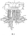
- a sensor module comprising a cylindrical, tubular shell 12 that is affixed to a mounting saddle 14.
- the mounting saddle surrounds and is clamped to a tubular mouthpiece 16.
- the mouthpiece 16 has a central lumen 18 and is preferably made from a suitable plastic, such as an acrylic.
- the outside diameter of the mouthpiece 16 is such that it can comfortably fit within the mouth of a subject and held there by the subject's lips during a phase of an exercise regimen in which that subject's RER is to be monitored.
- Concentrically disposed within the lumen 18 of the mouthpiece member 16 is a sampling tube 20 having a series of internal passages for directing inspired and expired air to and from the sensor module 10.
- the sampling tube 20 is maintained in a centered relation within the lumen 18 of the mouthpiece 16 by tubular standoff spacers 24 and 26. Extending through the lumen of spacer tube 24 is a fine capillary tube 28, preferably formed from a synthetic ionomer exhibiting selective permeability to water vapor.
- a synthetic ionomer exhibiting selective permeability to water vapor.
- One such material is available from the DuPont Corporation under the trademark, NAFION®.
- the greatly enlarged cross-sectional view of Figure 2 shows that the sampling tube 20 has a bullet-shape nose on opposed ends thereof.
- the nose 30 has a conically-shaped opening 32 leading to a right angled bore 34, the vertical portion of which is aligned with the lumen 36 of the NAFION tube 28 located in the lumen of the tubular strut 24. Because of the properties of the NAFION tube, moisture-ladened air expired from a subject's lungs has the moisture component thereof extracted by passing through the wall of the NAFION tube 28 and the dried air then enters a sampling chamber 38 formed in the base 40 of the mounting saddle 14.
- a bore 42 that extends through the tubular strut 26 and that is in fluid communication with a further bore 44 formed through the sample tube 20.
- inspired air is drawn through the conically-shaped opening 46 formed in the nose 48 and through a bore 50 formed internally of the tubular strut 26.
- the bore 50 is in fluid communication with a fluid pathway 52 formed in the base member 40. This pathway leads to the lumen 54 of the tubular strut 24 and picks up the moisture exiting through the walls of the NAFION tube 28, carrying that moisture through a bore 56 formed diametrically through the sampling tube 20 and out through a pitot tube 58 that is fitted into a counterbore 60 formed in the sampling tube.
- the sampling tube 20 is fastened to the base 40 of the mounting saddle 14 by means of an elongated screw, as at 61, such that the tubular standoffs 24 and 26 become clamped between the sampling tube 20 and the base 40 of the mounting saddle to thereby secure the several lumens in the tubular struts in appropriate alignment with mating lumens in the sampling tube member 20.
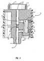
- FIG. 3 there is shown a greatly enlarged, cross-sectional view of the sensor module 10 comprising a preferred embodiment of the present invention. It comprises a body 62 preferably formed from a suitable metal, such as brass or aluminum and which is generally cylindrical and is contained within an insulating cover sleeve 64. An integrally formed annular hub 66 projects from the top surface 68 of the body member 62 forming a cup-like pocket dimensioned to contain a Zn-air cell 70 of a type commonly used for powering hearing aids.
- a suitable metal such as brass or aluminum
- An integrally formed annular hub 66 projects from the top surface 68 of the body member 62 forming a cup-like pocket dimensioned to contain a Zn-air cell 70 of a type commonly used for powering hearing aids.
- the annular projection 66 includes screw threads 72 on its outer diameter allowing a cap member (not shown) to be screwed onto the projection 66 for holding the cathode of the cell 70 in contact with the metal sensor body 62 and with the anode 74 of the cell in contact with a conductor connecting the cell to a constant current load circuit as will be described in greater detail herein below with the aid of Figure 5.
- a longitudinal bore 76 is aligned with an aperture 78 formed centrally in the bottom of the Zn-air cell 70.
- the bore 76 may be about 0.0052 in. in diameter over a majority of its length but narrows to about 0.025 in, midway along its length to create a choke 80.
- Two additional radially extending bores 82 and 84 are drilled through the side wall of the cylindrical body member 62 to intersect with the bore 76 and subsequently, the bore entrances are plugged with epoxy or other suitable material as at 86 and 88 in Figure 3.
- a further longitudinal bore 90 is formed inwardly from a bottom end of the body member 62 as is a counterbore 92. Placed within the bore 90 is a temperature sensitive resistance, such as a thermistor 94.
- the base 96 of the thermistor component fits into the counterbore 92 with lead terminals 98 extending outward from the sensor housing, allowing connection to the hot wire flowmeter circuit illustrated by the schematic diagram of Figure 6.
- a resistance heater 102 Bonded to the surface 100 of the sensor body 62 is a resistance heater 102 and which may comprise a Type DN-505 subminiature, proportionally controlled heater whose temperature can be programmed with a single external resistor. This device is well suited for regulating the ambient temperature within the sensor module 10.
- the Zn-air cell 70 has its cathode placed so that its air inlet port 78 is aligned with the lumen 76 and, as such, the air inlet port 78 of the cell is in fluid communication with expired air breathed into the mouthpiece 16 and which impinges upon the funnel-like lumen 32 of the sampling tube 20.
- the expired air breath then travels through the ionomer tube 28 that is selectively permeable to moisture, such that a relatively dry sample of the subject's expired air ultimately reaches the sampling chamber 38.
- the prototype module constructed by applicants has been especially designed to eliminate leaks within the system. Since flow, regulated by the Zn-air cell, is extremely low (less than 100 cc/min), minimizing unintentional airflow is imperative for proper operation.
- the air inlet chamber through the center of the module is the only entrance for air into the system. If O 2 is depleted near the cell 70, then a pressure drop within the chamber defined by the bores 72, 82 84 and 90 comprising the sensor occurs, necessarily creating a flow of O 2 into the Zn-air cell 70 to satisfy the constant current requirements.
- FIG. 4 there is schematically shown an electrical block diagram of the respiratory exchange ratio monitoring device. It includes the sensor module 10, a constant current load control circuit 106 connected to the Zn-air battery 70, and a thermistor flowmeter circuit 108 connected to the thermistor bead 94.
- the thermistor flowmeter circuit 108 feeds an analog output signal to an analog-to-digital converter 110 whose output is then connected to a data input terminal of a microprocessor-based controller or microcontroller 112.
- the microcontroller 112 controls the constant current load control circuit 106 and feeds information to a human interface device 114.
- a power supply circuit 116 provides the necessary operating potentials to the heater element 102 located in the sensor 10 to the microcontroller 112, the analog-to-digital converter 110 and the flowmeter circuit 108.
- the system automatically keeps the Zn-air battery circuit current constant by feedback control and monitors output signal proportional to the RER from the thermistor flow circuit.
- FIG. 5 there is shown an electrical circuit diagram of the Zn-air battery 70 coupled to its constant current load control circuit 106 that is enclosed by a dashed line box in Figure 5. While a particular design of a constant current load control circuit is illustrated, those skilled in the art can readily devise alternative arrangements and, hence, limitation of the invention to the one particularly illustrated in Figure 5 is not intended.
- the Zn-air battery 70 is connected with a sensing resistor 118 of relatively small ohmic value, such as about 20 ohms.
- the output of a digital-to-analog converter 110 serves to vary the voltage drop across the sensing resistor.
- the microcontroller 112 monitors the cell voltage, via input 120, as well as the amplified voltage from the sensing resistor 118 and, consequently, adjusts the output of the digital-to-analog converter 110 to keep current drain from the cell constant due to the applied feedback control.
- Figure 6 illustrates a schematic electrical diagram of the thermistor flow control circuit employed in the preferred embodiment.
- thermistor flow control circuit employed in the preferred embodiment.
- It includes a Wheatstone bridge 124 having the thermistor bead 94 in one arm thereof and an operational amplifier 126 connected across the output terminals 128 and 130 of the bridge.
- the operational amplifier 126 amplifies this signal and outputs a signal to a further operational amplifier 132 through a coupling resistor 134.
- the positive input terminal of the operational amplifier 132 connects to the wiper arm of a potentiometer 136 allowing the reference voltage applied to the operational amplifier 132 to be adjusted.
- a feedback resistor 138 is connected between the output of the operational amplifier 132 and its negative input terminal. The circuit components are selected such that the operational amplifier 132 functions to remove the DC baseline from the signal coming from the sensing amplifier 126.
- the resulting AC components are, in turn, amplified by the operational amplifier 140 and they are digitized by an analog-to-digital converter 110, allowing the waveforms to be processed by the microprocessor in the microcontroller module 112.
- the human interface 114 shown in Figure 4 may take on various forms. Where the purpose of the present invention is to provide an indication during exercise where the anaerobic threshold is reached, the interface may comprise first and second LED indicators where the first LED indicator is illuminated below the anaerobic threshold and the second indicator is made to glow when the anaerobic threshold is exceeded. If the goal of the subject in performing exercise is to lose weight (bum fat), then the exercise level should be maintained such that heart rate is a predetermined value less than heart rate at AT. On the other hand, if the goal of the exercise is to enhance cardiorespiratory performance, then the level of exercise should be such that the heart rate at AT is exceeded. Instead of using simple indicator lamps, it is also conceived that the human interface may be aural or tactile.
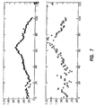
- the upper plot shows the variation of RER when measured in a laboratory environment using a suite of equipment like that described in the aforereferenced Anderson et al. '764 patent.
- the lower plot shows the variation of RER with exercise when using the direct method of RER measurement obtained from a prototype of the present invention.
- the correlation between the two sets of data indicates that the device of the present invention can be calibrated and reliably used to measure RER.
- the present invention provides a small, portable, relatively inexpensive instrument for directly measuring a subject's RER and, therefore, a level of exercise intensity. By simply breathing through the instrument while performing exercise, an indication can be given on whether the energy suhstrate being consumed is primarily fat or carbohydrates.
Landscapes
- Health & Medical Sciences (AREA)
- Life Sciences & Earth Sciences (AREA)
- Veterinary Medicine (AREA)
- Engineering & Computer Science (AREA)
- General Health & Medical Sciences (AREA)
- Biomedical Technology (AREA)
- Animal Behavior & Ethology (AREA)
- Public Health (AREA)
- Heart & Thoracic Surgery (AREA)
- Pulmonology (AREA)
- Physics & Mathematics (AREA)
- Biophysics (AREA)
- Pathology (AREA)
- Molecular Biology (AREA)
- Medical Informatics (AREA)
- Physiology (AREA)
- Emergency Medicine (AREA)
- Surgery (AREA)
- Anesthesiology (AREA)
- Hematology (AREA)
- Developmental Disabilities (AREA)
- Child & Adolescent Psychology (AREA)
- Psychology (AREA)
- Hospice & Palliative Care (AREA)
- Social Psychology (AREA)
- Psychiatry (AREA)
- Obesity (AREA)
- Measurement Of The Respiration, Hearing Ability, Form, And Blood Characteristics Of Living Organisms (AREA)
- Investigating Or Analyzing Materials By The Use Of Electric Means (AREA)
- Investigating Or Analyzing Materials By The Use Of Magnetic Means (AREA)
Applications Claiming Priority (1)
| Application Number | Priority Date | Filing Date | Title |
|---|---|---|---|
| US11/095,271 US7390304B2 (en) | 2005-03-31 | 2005-03-31 | Respiratory exchange ratio sensor |
Publications (2)
| Publication Number | Publication Date |
|---|---|
| EP1707120A2 true EP1707120A2 (fr) | 2006-10-04 |
| EP1707120A3 EP1707120A3 (fr) | 2007-07-25 |
Family
ID=36691580
Family Applications (1)
| Application Number | Title | Priority Date | Filing Date |
|---|---|---|---|
| EP06251762A Withdrawn EP1707120A3 (fr) | 2005-03-31 | 2006-03-30 | Capteur pour la détermination du quotient d'échange respiratoire |
Country Status (4)
| Country | Link |
|---|---|
| US (1) | US7390304B2 (fr) |
| EP (1) | EP1707120A3 (fr) |
| JP (1) | JP2006280937A (fr) |
| CA (1) | CA2540772A1 (fr) |
Families Citing this family (27)
| Publication number | Priority date | Publication date | Assignee | Title |
|---|---|---|---|---|
| US9779751B2 (en) | 2005-12-28 | 2017-10-03 | Breath Research, Inc. | Respiratory biofeedback devices, systems, and methods |
| US9788757B2 (en) | 2005-12-28 | 2017-10-17 | Breath Research, Inc. | Breathing biofeedback device |
| CA2602620A1 (fr) * | 2006-09-18 | 2008-03-18 | Invacare Corporation | Systeme d'alimentation en gaz respiratoire avec retroaction de l'utilisateur |
| NL2000310C2 (nl) * | 2006-11-09 | 2008-05-13 | Univ Twente | Inrichting voor het meten van het ammoniakgehalte in een gasmengsel. |
| US7607360B2 (en) * | 2007-08-27 | 2009-10-27 | Nihon Kohden Corporation | Adaptor for flow sensor |
| EP2187808B1 (fr) * | 2007-09-25 | 2021-05-26 | Oridion Medical (1987) Ltd. | Tube pour voies respiratoires amélioré |
| US8768489B2 (en) * | 2008-06-13 | 2014-07-01 | Gil Thieberger | Detecting and using heart rate training zone |
| US8302602B2 (en) | 2008-09-30 | 2012-11-06 | Nellcor Puritan Bennett Llc | Breathing assistance system with multiple pressure sensors |
| JP2010131264A (ja) * | 2008-12-05 | 2010-06-17 | Nippon Koden Corp | 呼吸気情報測定センサ |
| CA2839141C (fr) * | 2011-07-08 | 2018-11-20 | Global Nutrition & Health Inc. | Assistant personnalise pour l'alimentation et le bien-etre |
| US9364624B2 (en) | 2011-12-07 | 2016-06-14 | Covidien Lp | Methods and systems for adaptive base flow |
| US9498589B2 (en) | 2011-12-31 | 2016-11-22 | Covidien Lp | Methods and systems for adaptive base flow and leak compensation |
| US8844526B2 (en) | 2012-03-30 | 2014-09-30 | Covidien Lp | Methods and systems for triggering with unknown base flow |
| US9814438B2 (en) | 2012-06-18 | 2017-11-14 | Breath Research, Inc. | Methods and apparatus for performing dynamic respiratory classification and tracking |
| US10426426B2 (en) | 2012-06-18 | 2019-10-01 | Breathresearch, Inc. | Methods and apparatus for performing dynamic respiratory classification and tracking |
| US9981096B2 (en) | 2013-03-13 | 2018-05-29 | Covidien Lp | Methods and systems for triggering with unknown inspiratory flow |
| DE202013103647U1 (de) | 2013-08-12 | 2013-09-02 | Aspect Imaging Ltd. | Ein System zum Online-Messen und Steuern von O2-Fraktion, CO-Fraktion und CO2-Fraktion |
| US10449320B2 (en) | 2013-10-15 | 2019-10-22 | Fisher & Paykel Healthcare Limited | Sensing and control arrangements for respiratory device |
| US9808591B2 (en) | 2014-08-15 | 2017-11-07 | Covidien Lp | Methods and systems for breath delivery synchronization |
| US9950129B2 (en) | 2014-10-27 | 2018-04-24 | Covidien Lp | Ventilation triggering using change-point detection |
| US9925346B2 (en) | 2015-01-20 | 2018-03-27 | Covidien Lp | Systems and methods for ventilation with unknown exhalation flow |
| US10271766B1 (en) * | 2015-03-20 | 2019-04-30 | Barron Associates, Inc. | Systems, devices, and/or methods for measuring metabolic energy expenditure |
| EP3328276B8 (fr) | 2015-07-27 | 2023-10-11 | Massachusetts Institute of Technology | Appareil se rapportant à la surveillance du métabolisme |
| WO2019222463A1 (fr) | 2018-05-16 | 2019-11-21 | Massachusetts Institute Of Technology | Procédés et appareil pour échantillonnage et distribution passifs, proportionnels et sans vanne d'un gaz |
| WO2019222464A1 (fr) | 2018-05-16 | 2019-11-21 | Massachusetts Institute Of Technology | Mesure proportionnelle, passive de la consommation d'oxygène et de dioxyde de carbone pour l'évaluation de paramètres métaboliques |
| US11324954B2 (en) | 2019-06-28 | 2022-05-10 | Covidien Lp | Achieving smooth breathing by modified bilateral phrenic nerve pacing |
| US12257437B2 (en) | 2020-09-30 | 2025-03-25 | Covidien Lp | Intravenous phrenic nerve stimulation lead |
Citations (5)
| Publication number | Priority date | Publication date | Assignee | Title |
|---|---|---|---|---|
| US4462764A (en) | 1981-11-12 | 1984-07-31 | Zandt Hillard C Van | Hydraulic long stroke pump |
| US5060656A (en) | 1990-05-22 | 1991-10-29 | Aerosport, Inc. | Metabolic rate analyzer |
| US5117674A (en) | 1990-05-22 | 1992-06-02 | Aerosport, Inc. | Metabolic rate analyzer |
| US5297558A (en) | 1993-03-12 | 1994-03-29 | Medical Graphics Corporation | Algorithm for prescribing an exercise regimen to enhance fat burning and cardiovascular fitness |
| US6554776B1 (en) | 2001-11-21 | 2003-04-29 | Medical Graphics Corporation | Method for detecting anaerobic threshold and prescribing a training zone to maximize fat utilization or improved cardiovascular fitness |
Family Cites Families (5)
| Publication number | Priority date | Publication date | Assignee | Title |
|---|---|---|---|---|
| US3514377A (en) * | 1967-11-27 | 1970-05-26 | Gen Electric | Measurement of oxygen-containing gas compositions and apparatus therefor |
| US5089113A (en) * | 1988-07-22 | 1992-02-18 | Ford Motor Company | Measurement and control of exhaust gas recirculation with an oxygen pumping device |
| US20070225612A1 (en) * | 1996-07-15 | 2007-09-27 | Mace Leslie E | Metabolic measurements system including a multiple function airway adapter |
| US7108659B2 (en) * | 2002-08-01 | 2006-09-19 | Healthetech, Inc. | Respiratory analyzer for exercise use |
| WO2004041084A1 (fr) * | 2002-11-05 | 2004-05-21 | Craig Thomas Flanagan | Calorimetre indirect |
-
2005
- 2005-03-31 US US11/095,271 patent/US7390304B2/en active Active
-
2006
- 2006-03-22 CA CA002540772A patent/CA2540772A1/fr not_active Abandoned
- 2006-03-30 EP EP06251762A patent/EP1707120A3/fr not_active Withdrawn
- 2006-03-30 JP JP2006092800A patent/JP2006280937A/ja active Pending
Patent Citations (5)
| Publication number | Priority date | Publication date | Assignee | Title |
|---|---|---|---|---|
| US4462764A (en) | 1981-11-12 | 1984-07-31 | Zandt Hillard C Van | Hydraulic long stroke pump |
| US5060656A (en) | 1990-05-22 | 1991-10-29 | Aerosport, Inc. | Metabolic rate analyzer |
| US5117674A (en) | 1990-05-22 | 1992-06-02 | Aerosport, Inc. | Metabolic rate analyzer |
| US5297558A (en) | 1993-03-12 | 1994-03-29 | Medical Graphics Corporation | Algorithm for prescribing an exercise regimen to enhance fat burning and cardiovascular fitness |
| US6554776B1 (en) | 2001-11-21 | 2003-04-29 | Medical Graphics Corporation | Method for detecting anaerobic threshold and prescribing a training zone to maximize fat utilization or improved cardiovascular fitness |
Also Published As
| Publication number | Publication date |
|---|---|
| JP2006280937A (ja) | 2006-10-19 |
| EP1707120A3 (fr) | 2007-07-25 |
| US20060229526A1 (en) | 2006-10-12 |
| US7390304B2 (en) | 2008-06-24 |
| CA2540772A1 (fr) | 2006-09-30 |
Similar Documents
| Publication | Publication Date | Title |
|---|---|---|
| US7390304B2 (en) | Respiratory exchange ratio sensor | |
| JP4472533B2 (ja) | 診断用ガス分析装置 | |
| EP2259723B1 (fr) | Transducteur d'analyseur métabolique | |
| US5285794A (en) | Respiratory gas monitor | |
| US3523529A (en) | Oxygen consumption computer | |
| CN103338807B (zh) | 自动的流体输送系统及方法 | |
| US4572208A (en) | Metabolic gas monitoring apparatus and method | |
| US20140366610A1 (en) | Gas sensor with heater | |
| WO2002091921A1 (fr) | Procede et materiel de mesure de la concentration de monoxyde d'azote dans l'air expire | |
| AU2002253206A1 (en) | Method and measuring equipment for measuring nitric oxide concentration in exhaled air | |
| ATE204491T1 (de) | Gerät zur kontrollierten zudosierung von no zur atemluft von patienten | |
| WO2002068032A3 (fr) | Dispositifs nasaux | |
| US20070186929A1 (en) | Method and System to Determine Nasal Resistance to Airflow | |
| Schulz et al. | The validity of the telemetric system CORTEX X1 in the ventilatory and gas exchange measurement during exercise | |
| JP2016523657A (ja) | モジュール式フロー・カセット | |
| WO2018226639A1 (fr) | Dispositif analyseur d'haleine | |
| WO2005051188A1 (fr) | Procede et appareil permettant l'estimation du quotient respiratoire metabolique au repos | |
| EP3220817A1 (fr) | Procédé et dispositif destinés à déterminer la santé d'un sujet | |
| US20140371619A1 (en) | Gas sensor with heater | |
| US7556039B1 (en) | Sidestream gas sampling system using a capillary tube flow sensor | |
| CN110741243B (zh) | 用于以温度补偿的方式光学检测流体的氧含量的设备 | |
| US2916033A (en) | Method and apparatus for determining | |
| WO2004041084A1 (fr) | Calorimetre indirect | |
| McIlroy et al. | Transcutaneous blood gas measurements using a mass spectrometer | |
| Nicholson et al. | The performance of a variable-flow indirect calorimeter |
Legal Events
| Date | Code | Title | Description |
|---|---|---|---|
| PUAI | Public reference made under article 153(3) epc to a published international application that has entered the european phase |
Free format text: ORIGINAL CODE: 0009012 |
|
| AK | Designated contracting states |
Kind code of ref document: A2 Designated state(s): AT BE BG CH CY CZ DE DK EE ES FI FR GB GR HU IE IS IT LI LT LU LV MC NL PL PT RO SE SI SK TR |
|
| AX | Request for extension of the european patent |
Extension state: AL BA HR MK YU |
|
| PUAL | Search report despatched |
Free format text: ORIGINAL CODE: 0009013 |
|
| AK | Designated contracting states |
Kind code of ref document: A3 Designated state(s): AT BE BG CH CY CZ DE DK EE ES FI FR GB GR HU IE IS IT LI LT LU LV MC NL PL PT RO SE SI SK TR |
|
| AX | Request for extension of the european patent |
Extension state: AL BA HR MK YU |
|
| RIC1 | Information provided on ipc code assigned before grant |
Ipc: G01N 33/497 20060101ALI20070621BHEP Ipc: A61B 5/087 20060101ALI20070621BHEP Ipc: A61B 5/097 20060101ALI20070621BHEP Ipc: A61B 5/083 20060101AFI20060801BHEP |
|
| 17P | Request for examination filed |
Effective date: 20080117 |
|
| 17Q | First examination report despatched |
Effective date: 20080220 |
|
| AKX | Designation fees paid |
Designated state(s): AT BE BG CH CY CZ DE DK EE ES FI FR GB GR HU IE IS IT LI LT LU LV MC NL PL PT RO SE SI SK TR |
|
| GRAP | Despatch of communication of intention to grant a patent |
Free format text: ORIGINAL CODE: EPIDOSNIGR1 |
|
| STAA | Information on the status of an ep patent application or granted ep patent |
Free format text: STATUS: THE APPLICATION IS DEEMED TO BE WITHDRAWN |
|
| 18D | Application deemed to be withdrawn |
Effective date: 20081125 |