EP1707342B1 - Appareil de fabrication d'objets tridimensionnels à partir d'une poudre et méthode - Google Patents
Appareil de fabrication d'objets tridimensionnels à partir d'une poudre et méthode Download PDFInfo
- Publication number
- EP1707342B1 EP1707342B1 EP06006765.9A EP06006765A EP1707342B1 EP 1707342 B1 EP1707342 B1 EP 1707342B1 EP 06006765 A EP06006765 A EP 06006765A EP 1707342 B1 EP1707342 B1 EP 1707342B1
- Authority
- EP
- European Patent Office
- Prior art keywords
- powder
- container
- virgin
- process chamber
- line
- Prior art date
- Legal status (The legal status is an assumption and is not a legal conclusion. Google has not performed a legal analysis and makes no representation as to the accuracy of the status listed.)
- Ceased
Links
Images




Classifications
-
- B—PERFORMING OPERATIONS; TRANSPORTING
- B65—CONVEYING; PACKING; STORING; HANDLING THIN OR FILAMENTARY MATERIAL
- B65G—TRANSPORT OR STORAGE DEVICES, e.g. CONVEYORS FOR LOADING OR TIPPING, SHOP CONVEYOR SYSTEMS OR PNEUMATIC TUBE CONVEYORS
- B65G53/00—Conveying materials in bulk through troughs, pipes or tubes by floating the materials or by flow of gas, liquid or foam
- B65G53/04—Conveying materials in bulk pneumatically through pipes or tubes; Air slides
- B65G53/16—Gas pressure systems operating with fluidisation of the materials
- B65G53/18—Gas pressure systems operating with fluidisation of the materials through a porous wall
- B65G53/22—Gas pressure systems operating with fluidisation of the materials through a porous wall the systems comprising a reservoir, e.g. a bunker
-
- B—PERFORMING OPERATIONS; TRANSPORTING
- B22—CASTING; POWDER METALLURGY
- B22F—WORKING METALLIC POWDER; MANUFACTURE OF ARTICLES FROM METALLIC POWDER; MAKING METALLIC POWDER; APPARATUS OR DEVICES SPECIALLY ADAPTED FOR METALLIC POWDER
- B22F12/00—Apparatus or devices specially adapted for additive manufacturing; Auxiliary means for additive manufacturing; Combinations of additive manufacturing apparatus or devices with other processing apparatus or devices
- B22F12/50—Means for feeding of material, e.g. heads
- B22F12/52—Hoppers
-
- B—PERFORMING OPERATIONS; TRANSPORTING
- B33—ADDITIVE MANUFACTURING TECHNOLOGY
- B33Y—ADDITIVE MANUFACTURING, i.e. MANUFACTURING OF THREE-DIMENSIONAL [3D] OBJECTS BY ADDITIVE DEPOSITION, ADDITIVE AGGLOMERATION OR ADDITIVE LAYERING, e.g. BY 3D PRINTING, STEREOLITHOGRAPHY OR SELECTIVE LASER SINTERING
- B33Y30/00—Apparatus for additive manufacturing; Details thereof or accessories therefor
-
- B—PERFORMING OPERATIONS; TRANSPORTING
- B33—ADDITIVE MANUFACTURING TECHNOLOGY
- B33Y—ADDITIVE MANUFACTURING, i.e. MANUFACTURING OF THREE-DIMENSIONAL [3D] OBJECTS BY ADDITIVE DEPOSITION, ADDITIVE AGGLOMERATION OR ADDITIVE LAYERING, e.g. BY 3D PRINTING, STEREOLITHOGRAPHY OR SELECTIVE LASER SINTERING
- B33Y40/00—Auxiliary operations or equipment, e.g. for material handling
-
- B—PERFORMING OPERATIONS; TRANSPORTING
- B22—CASTING; POWDER METALLURGY
- B22F—WORKING METALLIC POWDER; MANUFACTURE OF ARTICLES FROM METALLIC POWDER; MAKING METALLIC POWDER; APPARATUS OR DEVICES SPECIALLY ADAPTED FOR METALLIC POWDER
- B22F12/00—Apparatus or devices specially adapted for additive manufacturing; Auxiliary means for additive manufacturing; Combinations of additive manufacturing apparatus or devices with other processing apparatus or devices
- B22F12/40—Radiation means
- B22F12/41—Radiation means characterised by the type, e.g. laser or electron beam
-
- B—PERFORMING OPERATIONS; TRANSPORTING
- B22—CASTING; POWDER METALLURGY
- B22F—WORKING METALLIC POWDER; MANUFACTURE OF ARTICLES FROM METALLIC POWDER; MAKING METALLIC POWDER; APPARATUS OR DEVICES SPECIALLY ADAPTED FOR METALLIC POWDER
- B22F12/00—Apparatus or devices specially adapted for additive manufacturing; Auxiliary means for additive manufacturing; Combinations of additive manufacturing apparatus or devices with other processing apparatus or devices
- B22F12/40—Radiation means
- B22F12/44—Radiation means characterised by the configuration of the radiation means
-
- B—PERFORMING OPERATIONS; TRANSPORTING
- B22—CASTING; POWDER METALLURGY
- B22F—WORKING METALLIC POWDER; MANUFACTURE OF ARTICLES FROM METALLIC POWDER; MAKING METALLIC POWDER; APPARATUS OR DEVICES SPECIALLY ADAPTED FOR METALLIC POWDER
- B22F12/00—Apparatus or devices specially adapted for additive manufacturing; Auxiliary means for additive manufacturing; Combinations of additive manufacturing apparatus or devices with other processing apparatus or devices
- B22F12/40—Radiation means
- B22F12/49—Scanners
-
- B—PERFORMING OPERATIONS; TRANSPORTING
- B22—CASTING; POWDER METALLURGY
- B22F—WORKING METALLIC POWDER; MANUFACTURE OF ARTICLES FROM METALLIC POWDER; MAKING METALLIC POWDER; APPARATUS OR DEVICES SPECIALLY ADAPTED FOR METALLIC POWDER
- B22F2998/00—Supplementary information concerning processes or compositions relating to powder metallurgy
-
- B—PERFORMING OPERATIONS; TRANSPORTING
- B29—WORKING OF PLASTICS; WORKING OF SUBSTANCES IN A PLASTIC STATE IN GENERAL
- B29C—SHAPING OR JOINING OF PLASTICS; SHAPING OF MATERIAL IN A PLASTIC STATE, NOT OTHERWISE PROVIDED FOR; AFTER-TREATMENT OF THE SHAPED PRODUCTS, e.g. REPAIRING
- B29C64/00—Additive manufacturing, i.e. manufacturing of three-dimensional [3D] objects by additive deposition, additive agglomeration or additive layering, e.g. by 3D printing, stereolithography or selective laser sintering
- B29C64/30—Auxiliary operations or equipment
- B29C64/307—Handling of material to be used in additive manufacturing
- B29C64/321—Feeding
- B29C64/329—Feeding using hoppers
-
- Y—GENERAL TAGGING OF NEW TECHNOLOGICAL DEVELOPMENTS; GENERAL TAGGING OF CROSS-SECTIONAL TECHNOLOGIES SPANNING OVER SEVERAL SECTIONS OF THE IPC; TECHNICAL SUBJECTS COVERED BY FORMER USPC CROSS-REFERENCE ART COLLECTIONS [XRACs] AND DIGESTS
- Y02—TECHNOLOGIES OR APPLICATIONS FOR MITIGATION OR ADAPTATION AGAINST CLIMATE CHANGE
- Y02P—CLIMATE CHANGE MITIGATION TECHNOLOGIES IN THE PRODUCTION OR PROCESSING OF GOODS
- Y02P10/00—Technologies related to metal processing
- Y02P10/25—Process efficiency
Definitions
- This invention relates to a material handling apparatus, and more particularly to a closed system for handling powdered or fine granular materials, the system enabling the powdered material to be readily unloaded from a container substantially without the discharge or escape of dust.
- a particular useful application that will be described herein is the use of the invention for bulk feeding of powder into a laser sintering process.
- containers are now commercially available from Semi-Bulk Systems, Inc. of St. Louis, Missouri, for receiving, transporting and unloading "semi-bulk" quantities (e.g., 2000-4000 pounds or more) of powdered or finely divided granular material.
- "semi-bulk" quantities e.g., 2000-4000 pounds or more
- Such containers have a rigid molded plastic pallet base and a flexible plastic film bag secured thereto. Methods and apparatus for filling such bags while minimizing generated dust have been described, with one example described in aforementioned U.S. Patent Nos. 4,182,386 .
- U.S. Patent No. 5,271,439 A useful system for unloading powdered materials from such flexible containers is described in U.S. Patent No. 5,271,439 . Because many commercial powdered materials may agglomerate and form lumps during transport and storage, the system described in U.S. Patent No. 5,271,439 employs a joint strategy of vibration and mechanical squeezing of the flexible container while introducing compressed gas into the flexible container to fluidize the powdered material and assist it to flow out of the base of the container. Further, the base of the flexible container is sloped toward one side to help the fluidized powder flow toward the outlet line. In some implementations the entire flexible container may even be tilted to aid flow.
- An important application requiring a supply of powder feed is the use of laser sintering technology to produce 3-dimensional articles from powder.
- a freeform fabrication technology is the selective laser sintering process practiced in systems available from 3D Systems, Inc., in which articles are produced from a laser-fusible powder in layerwise fashion. According to this process, a thin layer of powder is dispensed and then fused, melted, or sintered, by laser energy that is directed to those portions of the powder corresponding to a cross-section of the article.
- Conventional selective laser sintering systems such as the Vanguard system available from 3D Systems, Inc., position the laser beam by way of an optics system using galvanometer-driven mirrors that deflect the laser beam.
- the deflection of the laser beam is controlled, in combination with modulation of the laser itself, to direct laser energy to those locations of the fusible powder layer corresponding to the cross-section of the article to be formed in that layer.
- the computer based control system is programmed with information indicative of the desired boundaries of a plurality of cross-sections of the part to be produced.
- the laser may be scanned across the powder in raster fashion, with modulation of the laser affected in combination therewith, or the laser may be directed in vector fashion.
- cross-sections of articles are formed in a powder layer by fusing powder along the outline of the cross-section in vector fashion either before or after a raster scan that "fills" the area within the vector-drawn outline.
- an additional layer of powder is then dispensed, and the process repeated, with fused portions of later layers fusing to fused portions of previous layers (as appropriate for the article), until the article is complete.
- Document US 6,401,001 relates to layer manufacturing using deposition of fused droplets.
- a solid freeform fabrication process and apparatus for making a three-dimensional object are suggested therein.
- the process comprises the steps of positioning a material deposition sub-system a selected distance from a target surface, operating this sub-system to deposit materials onto the target surface, and during the material deposition process, moving the deposition sub-system and the target surface relative to one another along selected directions in a plane defined by first and second coordinate directions and in a third direction orthogonal to this plane to form deposition materials into a three dimensional shape.
- Document DE 101 05 504 A1 relates to a device for treating powder for a device which produces three-dimensional objects by means of a generative manufacturing method.
- Said device comprises a store tank for the powder, a base and a lateral wall, wherein the storage tank is provided with a chamber which comprises a wall which is permeable for a fluidic medium, in addition to comprising a device for introducing a fluidic medium into the chamber.
- the containers to be used can be either rigid or flexible.
- pneumatic powder transfer system is used in conjunction with a laser sintering apparatus to produce three-dimensional articles.
- the pneumatic powder transfer system is used in conjunction with a powder processing unit that combines and blends powders for a laser sintering apparatus to produce three-dimensional articles.
- the pneumatic powder transfer system uses both a continuous and an occasional higher pulse of compressed gas to effectively fluidize and convey powder.
- the pneumatic powder transfer system uses a supplemental flow of compressed gas into the outlet stream to improve the transfer effectiveness of the system.
- the pneumatic powder transfer system has a bottom shaped to slope downward to a central outlet for powder.
- the pneumatic powder transfer system has a powder container can be either rigid or flexible and collapsible.
- powder can be transferred from a container in an automated manner with minimal manual labor.
- the method is a method according to claim 9 for producing a bed of powder in the process chamber of a laser sintering machine in which a three-dimensional article is formed in layerwise.
- FIG. 1 illustrates, by way of background, a prior art flexible container unloading system, as described in U.S. Pat. No. 5,271,439 .
- the system represented generally by the numeral 50, includes a flexible bag 54 that is sealably attached to a substantially rigid base 58 of a water impervious synthetic resin.
- the base has a plurality of openings 60 for receiving the tines of a forklift (not shown) for transporting the bag-base combination.
- a porous diaphragm (not shown) covers the upper surface of base 58 and is secured to the outer periphery of the base.
- the diaphragm overlies the base, such that a plenum is defined between the diaphragm and the base.
- a frame indicated generally at 66, is made up of a plurality of frame members including side frame members 70 and top frame members 74 which form a tall rectangular superstructure for supporting the flexible wall bag 54.
- a platform 78 on which base 58 rests is sloped forwardly to facilitate flow of material from the container through a bottom outlet (not shown) of base 58.
- Mechanical arms 80 on each side of flexible bag 54 are equipped with a vibrating function and can be moved inward to squeeze flexible bag 54. The combination of vibration and mechanical squeezing is used to facilitate the movement of powders toward the bottom of bag 54 and out the bottom outlet.
- a laser sintering system for producing 3-dimensional articles is shown in Figure 2 and represented generally by the numeral 150.
- a carbon dioxide laser 108 and its associated scanning system 114 is shown mounted in a unit above a process chamber 152 that includes a top target area 186 of powder bed 190, and a spreading roller 180.
- the process chamber 152 maintains the appropriate temperature and atmospheric composition (typically an inert atmosphere such as nitrogen) for the fabrication of the article.
- a feed hopper 162 and 164 is used to periodically deposit powder 184 onto process chamber floor 206 where it is spread by counter-rotating roller 180 that is moved in reciprocating fashion by drive system 182.
- a feed line 161 feeds powder into the laser sintering system where it enters the top section of feed hopper 162. The method for depositing and spreading powder in both directions in this approach is described completely in U.S. Patent application No. 10/856,303 , assigned to the assignee of the present invention.
- a laser beam 154 is generated by laser 108, and aimed at target area 186 by way of optics-mirror scanning system 114, generally including galvanometer-driven mirrors that deflect the laser beam.
- the laser and galvanometer systems are isolated from the hot process chamber 152 by a laser window 156.
- the laser window 156 is situated within the periphery formed by radiant heater elements 160 that heat the target area 186 of the part bed below. These heater elements 160 may be ring shaped (rectangular or circular) panels or radiant heater rods that are arrayed about the laser window 156.
- the deflection of the laser beam 154 is controlled in combination with modulation of laser 108 itself, to direct laser energy to those locations of the fusible powder layer in the target area 186 on the exposed surface of the part cake 190 corresponding to the cross-section of the article to be formed in that layer.
- Scanning system 114 may scan the laser beam 154 across the powder in a raster-scan fashion, or in vector fashion. Once the cross-section is formed the part cake 190 is lowered one layer thickness by the drive system 172 lowering support platform 170 on which is the part cake 190.
- Virgin powder refers to fresh powder fed to a system.
- Overflow powder is the excess powder pushed out of the build chamber, such as the powder in containers 188 in Figure 2 .
- Recovered powder is powder recovered outside the build or process chamber when the manufactured parts in the part cake are removed from the system. Such recovered powder is collected and recovered outside of the laser sintering machine in a device usually referred to as a breakout station.
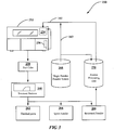
- FIG. 3 A compact and reliable automated system for feeding, removing and recycling powders to laser sintering systems is shown in Figure 3 and represented generally by the numeral 250. This system is described in the aforementioned patent application serial number 11/077,304 .
- One or more laser sintering machines 252 similar to that described in Figure 2 , are equipped with a feed hopper 254 and one or more overflow containers 256. Not shown in Figure 3 , is a dense phase transporter located within laser sintering machine 252 which transfers overflow powder from container 256 back to feed hopper 254, eliminating a significant powder-handling load from the external powder processing unit 270.
- part cake 258 which consists of the fabricated parts and the unfused powder around those parts, is moved to break-out station 260.
- part cake 2.58 into finished parts 262, lower quality or spent powder 264, and recovered powder 266 for recycle is accomplished mechanically.
- Spent powder is normally composed of larger hard agglomerates created by powder close to the hot parts. Spent powder is not suitable for recycle and is discarded.
- a dense phase transporter (not shown) then transports recovered powder 266 to powder processing unit 270 where it is combined with new powder 268 to be fed back to the machine feed hopper 254.
- the system can be used to feed virgin powder directly to a laser sintering machine if desired via line 163.
- the powder processing unit 270 provides the function of blending and feeding a desired mixture of virgin and recovered powder for laser sintering and a typical one is described in more detail in the aforementioned patent application serial number 11/077,304 .
- Feed line 161 corresponds to feed line 161 in Figure 2 . Not shown is the network of gas piping and controls that drive the dense phase pneumatic transfers throughout the system.
- the bulk feeding of new powder into the system is represented by the virgin (new) powder feeder 268.
- the instant invention employs a pneumatic powder transfer system and a contained and automated bulk powder unloading system that is reliable, mechanically simple, and cost effective.
- the powder transfer system employs a container for the virgin powder that can be stationary or portable and reusable.
- the stationary container is filled in place.
- the container is portable and reusable. It is filled by a powder supplier and shipped to a location where it is connected to the user's laser sintering system and to a supply of compressed air. After use it is returned for refill.
- Figure 4 represented generally by the numeral 300, is a pneumatic powder transfer system of the instant invention.
- the pneumatic powder transfer system consists of a container 304 and a substantially rigid base 308.
- the illustrated structure of two separate elements (a container 304 and a base 308) is not a requirement of the instant invention in that it can also be of a one-piece construction. However, a two piece structure as shown allows the possibility of keeping a base 308 in place and shipping the container 304 after use to have it refilled.
- Container 304 can also be a flexible and collapsible bag that can be collapsed into the base to enable more compact shipping for refilling.
- Container 304 can also be a substantially rigid container.
- container 304 has a porous diaphragm (not shown) that covers an upper surface of base 308 and is secured to the outer periphery of the base.
- the diaphragm overlies the base, such that a plenum is defined between the diaphragm and the base.
- Compressed gas introduced into port 312 in base 308 flows into the plenum and passes through the porous diaphragm and into container 304 where it partially or completely fluidizes the material forming the load.
- base 308 and the bottom of container 304 form an inclined slope that induces fluidized powder to flow down toward the center of container 308 to an outlet that exits from port 320 from base 308 rather than toward one side as has been done previously.
- container 304 does not have a top vent so the compressed fluidizing gas entering through port 312 not only fluidizes the contained powder but slightly pressurizes the container and thereby provides the driving force to transport powder out of outlet port 320, which is the only exit point for the compressed gas.
- Additional compressed gas input port 324 in base 308 is available to further augment flow as will be clearer in Figure 5 .
- FIG 5 is a side view of the pneumatic powder transfer system of Figure 4 , represented generally by the numeral 400.
- the pneumatic powder transfer system consists of a container 304 and a substantially rigid base 308. Having two separate elements (a container 304 and a base 308) is not a requirement of the instant invention in that it can also be of a one-piece construction.
- Inlet port 312 in base 308 is the access point for connecting a compressed gas supply that feeds fluidizing gas through line 314 to the plenum (not shown) formed between a porous diaphragm and base 308.
- the compressed fluidizing gas creates enough pressure in container 304 to drive fluidized powder into exit line 316, which exits base 308 at outlet port 320.
- Inlet port 324 provides additional compressed gas via line 318 to exit line 316 to provide supplemental conveying gas when needed.
- FIG. 306 is another side view of the shipping and unloading system shown in Figure 5 .
- a source of compressed gas 326 provides gas through lines 330 and 334 to inlet port 312.
- Valves 331 and 333 can be manually operated or automatically via a computer controlled system. In operation valve 331 and line 330 provide a steady supply of fluidizing gas to inlet port 312 and through line 314 to fluidize powder in container 304. For the majority of the time this fluidizing gas is sufficient to move powder smoothly from container 304 and out of the system through outlet port 320. During this time valve 333 is closed.
- valve 333 When powder transfer is restricted due to a blockage or slows as the container is almost emptied valve 333 can be opened and pulsed gas flowed through line 334 to increase fluidization as well as increase pressure in container 304.
- the volume of pulsed gas is significantly higher than the normal fluidizing gas delivered through line 330.
- a feedback pressure control system (not shown) can be used to regulate valve 333 or it can be controlled manually. Alternately the pulsed gas system could have the structure of only one valve 331 which normally supplies fluidizing gas and occasionally supplies pulsed gas by opening much wider.
- Supplemental conveying gas line 338 controlled by valve 335, is also used to control the ratio of solids to air in the exit conveying line 316. The supplemental conveying gas dilutes the fluidized powder and improves flow.
- Figure 7 is a top view of the pneumatic powder transfer system container to show that the bottom outlet 360 of the container is centered to enable uniform flowing of the fluidized powder out of the container.
- Outlet 360 is connected to line 316 of Figure 6 .
- Viewing both outlet 360 of Figure 7 and the sloped bottom 315 of Figure 6 defines a bottom of the container that is sloped downwardly toward a centered outlet.
- the bottom outlet is located on the side of the container rather than the in the center.
- a side exit has been found to be functional in conjunction with the instant invention, but a center exit design is a preferred embodiment to achieve more complete emptying of the container 304 even when employed with a tilting stand, or vibration and/or mechanical squeezing.
Landscapes
- Engineering & Computer Science (AREA)
- Chemical & Material Sciences (AREA)
- Manufacturing & Machinery (AREA)
- Materials Engineering (AREA)
- Mechanical Engineering (AREA)
- Air Transport Of Granular Materials (AREA)
- Processing And Handling Of Plastics And Other Materials For Molding In General (AREA)
- Powder Metallurgy (AREA)
Claims (13)
- Un appareil de production d'articles tridimensionnels à partir d'une poudre, comprenant :(a) une chambre de traitement (152) au sein de l'appareil, dans laquelle est exécuté un processus de construction par couches pour produire des objets tridimensionnels ;(b) une ligne d'alimentation (161) vers l'appareil pour l'alimentation en poudre de la chambre de traitement (152) ; et(c) un système pneumatique de transfert de poudre (300) relié à la ligne d'alimentation (161) pour transporter de la poudre vierge vers la chambre d'alimentation (152) ;
le système pneumatique de transfert de poudre (300) comprenant :(i) un conteneur (304) pour la poudre vierge ;(ii) une première ligne (314, 330) apte à délivrer une alimentation stable de gaz comprimé vers le conteneur (304) pour fluidiser la poudre vierge dans le conteneur (304), et pour transporter la poudre vierge en un état fluidisé depuis le conteneur (304) ; et
caractérisé en ce que le système pneumatique de transfert de poudre comprend en outre(iii) une seconde ligne (334) pour délivrer un gaz comprimé additionnel sous forme d'un gaz pulsé à ladite première ligne (314, 330) pour augmenter la fluidisation de ladite poudre vierge. - L'appareil de la revendication 1, dans lequel le conteneur (304) pour de la poudre vierge comprend une base substantiellement rigide (308) qui lui est solidarisée de façon étanche.
- L'appareil de la revendication 2, dans lequel la première ligne (314, 330) est reliée à la base substantiellement rigide (308) pour délivrer du gaz comprimé à l'intérieur du conteneur (304) pour la poudre vierge pour fluidiser la poudre vierge dans le conteneur (304) et transporter la poudre vierge à l'état fluidisé depuis le conteneur.
- L'appareil selon l'une des revendications précédentes, dans lequel le conteneur (304) de poudre vierge est un sac flexible et écrasable, sac qui est en particulier solidarisé de façon étanche à la base substantiellement rigide (308).
- L'appareil selon l'une des revendications 1 à 3, dans lequel le conteneur (304) de poudre vierge est un conteneur rigide solidarisé de façon étanche à la base substantiellement rigide (308).
- L'appareil selon l'une des revendications précédentes, dans lequel le fond du conteneur (304) est incliné vers le bas en direction d'un orifice de sortie central.
- L'appareil selon l'une des revendications précédentes, comprenant en outre une unité de traitement de poudre reliée à la ligne d'alimentation.
- L'appareil de la revendication 7, dans lequel le système pneumatique de transfert de poudre est relié à l'unité de traitement de poudre pour transporter la poudre vierge vers la chambre de traitement.
- Un procédé de production d'un lit de poudre dans la chambre de traitement (152) d'une machine de frittage par laser (252) dans laquelle un article tridimensionnel est formé par couches, comprenant les étapes suivantes :a) alimentation pneumatique d'une poudre vierge depuis un conteneur de poudre vierge (304) vers une unité de traitement de poudre (270) ;b) dépôt d'une première partie de la poudre dans la chambre de traitement (152) et sur l'étendue d'une zone cible (186) ; etc) dans lequel l'étape d'alimentation pneumatique d'une poudre vierge d'un conteneur de poudre vierge (304) vers une unité de traitement de poudre (270) comprend les étapes suivantes :i. fluidisation de la poudre vierge dans le conteneur de poudre vierge (304) à un premier débit d'une première alimentation de gaz comprimé par l'intermédiaire d'une première ligne (312, 330) pour assurer une alimentation stable de gaz ;ii. pressurisation intermittente du conteneur avec un second débit de ladite première alimentation de gaz comprimé par l'intermédiaire d'une seconde ligne (334) ; etiii. retrait d'un flux fluidisé de la poudre depuis un orifice de sortie de fond (360) du conteneur de poudre.
- Le procédé de production d'un lit de poudre dans la chambre de traitement (152) d'une machine de frittage laser (252) de la revendication 9, comprenant en outre l'étape d'augmentation du flux fluidisé de la poudre par une seconde alimentation de gaz comprimé.
- Le procédé de production d'un lit de poudre dans la chambre de traitement (152) d'une machine de frittage laser (252) de la revendication 9 ou 10, comprenant en outre le dépôt d'une première partie de la poudre sur l'étendue de la zone cible (186) dans la chambre de traitement (152) depuis un premier côté jusqu'à un second côté opposé de la chambre de traitement.
- Le procédé de production d'un lit de poudre dans la chambre de traitement (152) d'une machine de frittage laser (252) de la revendication 10, comprenant en outre le dépôt d'une seconde partie de la poudre sur l'étendue de la zone cible (186) dans la chambre de traitement (152) depuis le second côté opposé jusqu'au premier côté.
- Le procédé de production d'un lit de poudre dans la chambre de traitement (152) d'une machine de frittage laser (252) selon l'une des revendications 9 à 12, comprenant en outre les étapes suivantes :(a) alimentation pneumatique de poudre depuis l'unité de traitement de poudre (270) vers une trémie d'alimentation (162) dans la machine de frittage laser (252) ; et(b) dépôt d'une première partie de la poudre depuis la trémie d'alimentation (162) vers la chambre de traitement (152) et sur l'étendue d'une zone cible (186).
Applications Claiming Priority (1)
| Application Number | Priority Date | Filing Date | Title |
|---|---|---|---|
| US11/096,143 US7296599B2 (en) | 2005-03-31 | 2005-03-31 | Pneumatic powder transport system |
Publications (3)
| Publication Number | Publication Date |
|---|---|
| EP1707342A2 EP1707342A2 (fr) | 2006-10-04 |
| EP1707342A3 EP1707342A3 (fr) | 2010-06-02 |
| EP1707342B1 true EP1707342B1 (fr) | 2018-01-03 |
Family
ID=36685898
Family Applications (1)
| Application Number | Title | Priority Date | Filing Date |
|---|---|---|---|
| EP06006765.9A Ceased EP1707342B1 (fr) | 2005-03-31 | 2006-03-30 | Appareil de fabrication d'objets tridimensionnels à partir d'une poudre et méthode |
Country Status (4)
| Country | Link |
|---|---|
| US (2) | US7296599B2 (fr) |
| EP (1) | EP1707342B1 (fr) |
| JP (1) | JP4919325B2 (fr) |
| DE (1) | DE102006014844A1 (fr) |
Families Citing this family (53)
| Publication number | Priority date | Publication date | Assignee | Title |
|---|---|---|---|---|
| US20100155985A1 (en) | 2008-12-18 | 2010-06-24 | 3D Systems, Incorporated | Apparatus and Method for Cooling Part Cake in Laser Sintering |
| US20110048317A1 (en) * | 2009-08-31 | 2011-03-03 | Heat And Control, Inc. | Portable, compact, food seasoning replenishment system |
| USD733765S1 (en) * | 2011-11-02 | 2015-07-07 | Gema Switzerland Gmbh | Powder feed hopper |
| US20140077422A1 (en) * | 2012-09-19 | 2014-03-20 | Pratt & Whitney Rocketdyne, Inc. | Reduced build mass additive manufacturing chamber |
| EP2969485B1 (fr) | 2013-03-15 | 2019-06-05 | 3D Systems, Inc. | Glissière pour systèmes de frittage laser |
| GB201310398D0 (en) | 2013-06-11 | 2013-07-24 | Renishaw Plc | Additive manufacturing apparatus and method |
| ES2725889T3 (es) * | 2013-06-10 | 2019-09-30 | Renishaw Plc | Aparato y método de solidificación selectiva por láser |
| KR20150115596A (ko) * | 2014-04-04 | 2015-10-14 | 가부시키가이샤 마쓰우라 기카이 세이사쿠쇼 | 3차원 조형 장치 및 3차원 형상 조형물의 제조 방법 |
| GB2546016B (en) | 2014-06-20 | 2018-11-28 | Velo3D Inc | Apparatuses, systems and methods for three-dimensional printing |
| US9446448B2 (en) * | 2014-12-02 | 2016-09-20 | The Exone Company | Recoaters for powder-layer three-dimensional printers |
| FR3032637A1 (fr) | 2015-02-16 | 2016-08-19 | Michelin & Cie | Procede de gestion d'une poudre dans une installation de fabrication additive comprenant une pluralite de machines |
| GB201505458D0 (en) | 2015-03-30 | 2015-05-13 | Renishaw Plc | Additive manufacturing apparatus and methods |
| US10391556B2 (en) * | 2015-04-28 | 2019-08-27 | General Electric Company | Powder transfer apparatus and method for additive manufacturing |
| US10315408B2 (en) | 2015-04-28 | 2019-06-11 | General Electric Company | Additive manufacturing apparatus and method |
| US10913206B2 (en) | 2015-08-03 | 2021-02-09 | Delavan, Inc | Systems and methods for post additive manufacturing processing |
| JP2018535121A (ja) | 2015-11-06 | 2018-11-29 | ヴェロ・スリー・ディー・インコーポレイテッド | 熟達した3次元印刷 |
| US10207454B2 (en) | 2015-12-10 | 2019-02-19 | Velo3D, Inc. | Systems for three-dimensional printing |
| US20170239891A1 (en) | 2016-02-18 | 2017-08-24 | Velo3D, Inc. | Accurate three-dimensional printing |
| CN107303606A (zh) * | 2016-04-22 | 2017-10-31 | 中国科学院沈阳自动化研究所 | 一种送粉式激光3d打印载气式送粉器 |
| KR102171904B1 (ko) * | 2016-05-12 | 2020-11-02 | 휴렛-팩커드 디벨롭먼트 컴퍼니, 엘.피. | 축조 재료 용기 |
| JP6674034B2 (ja) | 2016-05-12 | 2020-04-01 | ヒューレット−パッカード デベロップメント カンパニー エル.ピー.Hewlett‐Packard Development Company, L.P. | 造形材料容器 |
| WO2018022002A1 (fr) | 2016-07-26 | 2018-02-01 | Hewlett-Packard Development Company, L.P. | Refroidissement de matériau de construction dans un système d'impression 3d |
| WO2017196355A1 (fr) * | 2016-05-12 | 2017-11-16 | Hewlett-Packard Development Company, L.P. | Post-traitement dans des systèmes d'impression 3d |
| US11104073B2 (en) * | 2016-05-12 | 2021-08-31 | Hewlett-Packard Development Company, L.P. | Build material container |
| JP6868631B2 (ja) * | 2016-05-12 | 2021-05-12 | ヒューレット−パッカード デベロップメント カンパニー エル.ピー.Hewlett‐Packard Development Company, L.P. | 造形材料容器 |
| US9486962B1 (en) * | 2016-05-23 | 2016-11-08 | The Exone Company | Fine powder recoater for three-dimensional printer |
| WO2018005439A1 (fr) | 2016-06-29 | 2018-01-04 | Velo3D, Inc. | Impression 3d et imprimantes 3d |
| US11691343B2 (en) | 2016-06-29 | 2023-07-04 | Velo3D, Inc. | Three-dimensional printing and three-dimensional printers |
| CN106041082B (zh) * | 2016-07-27 | 2018-03-30 | 沈阳航空航天大学 | 一种用于金属激光增材制造的模块化箱体 |
| US20180095450A1 (en) | 2016-09-30 | 2018-04-05 | Velo3D, Inc. | Three-dimensional objects and their formation |
| DE102016220949B3 (de) * | 2016-10-25 | 2018-04-19 | Trumpf Laser- Und Systemtechnik Gmbh | Verfahren zum schnellen Inertisieren einer Kammer einer Maschine zur additiven Fertigung von Bauteilen und zugehörige Maschine |
| US10661341B2 (en) | 2016-11-07 | 2020-05-26 | Velo3D, Inc. | Gas flow in three-dimensional printing |
| NL2017864B1 (en) | 2016-11-24 | 2018-06-01 | Additive Ind Bv | System for producing an object by means of additive manufacturing |
| US11148358B2 (en) | 2017-01-03 | 2021-10-19 | General Electric Company | Methods and systems for vacuum powder placement in additive manufacturing systems |
| US20180186080A1 (en) | 2017-01-05 | 2018-07-05 | Velo3D, Inc. | Optics in three-dimensional printing |
| WO2018160807A1 (fr) | 2017-03-02 | 2018-09-07 | Velo3D, Inc. | Impression tridimensionnelle d'objets tridimensionnels |
| US10449696B2 (en) * | 2017-03-28 | 2019-10-22 | Velo3D, Inc. | Material manipulation in three-dimensional printing |
| BR112020001860A2 (pt) | 2017-07-28 | 2020-07-28 | Hewlett-Packard Development Company, L.P. | impressora tridimensional |
| US11325308B2 (en) | 2017-09-01 | 2022-05-10 | Hewlett-Packard Development Company, L.P. | Moving powder in a 3D printing system |
| FR3074484B1 (fr) * | 2017-12-05 | 2021-04-30 | Addup | Container inertable de transport d'une poudre de fabrication additive |
| US10272525B1 (en) | 2017-12-27 | 2019-04-30 | Velo3D, Inc. | Three-dimensional printing systems and methods of their use |
| WO2019191607A1 (fr) * | 2018-03-29 | 2019-10-03 | Applied Materials, Inc. | Système de transfert de poudre pour fabrication additive |
| US12121964B2 (en) | 2018-11-07 | 2024-10-22 | James J. Myrick | Processes, compositions and systems for 2D and 3D printing |
| US12311602B2 (en) | 2019-06-25 | 2025-05-27 | Nikon Slm Solutions Ag | Powder supply system, method of operating a powder supply system and apparatus for producing a three-dimensional work piece |
| CA3148849A1 (fr) | 2019-07-26 | 2021-02-04 | Velo3D, Inc. | Assurance qualite dans la formation d'objets tridimensionnels |
| GB2589825B (en) * | 2019-10-02 | 2024-05-29 | Lpw Technology Ltd | A docking arrangement for an additive manufacturing process |
| WO2021150204A1 (fr) | 2020-01-20 | 2021-07-29 | Hewlett-Packard Development Company, L.P. | Préparation d'unité de construction |
| EP4037892A4 (fr) * | 2020-03-02 | 2023-06-14 | Hewlett-Packard Development Company, L.P. | Désagglomération d'objet |
| GB202011515D0 (en) * | 2020-07-24 | 2020-09-09 | Additive Manufacturing Tech Ltd | Additive manufacturing |
| CN112719307A (zh) * | 2020-12-31 | 2021-04-30 | 苏州倍丰激光科技有限公司 | 一种连续式3d打印供粉系统 |
| EP4380744A1 (fr) * | 2021-08-06 | 2024-06-12 | Nikon SLM Solutions AG | Système et procédé de distribution de poudre de matière première à une pluralité de machines de fabrication additive |
| KR102495518B1 (ko) * | 2021-08-17 | 2023-02-06 | 주식회사신도리코 | Sls 방식 3d 프린터의 원료 걸림 제거 장치 및 방법 |
| US12337543B2 (en) | 2022-01-14 | 2025-06-24 | Sakuu Corporation | Printing method for additive manufacturing, including in-situ powder regeneration |
Citations (3)
| Publication number | Priority date | Publication date | Assignee | Title |
|---|---|---|---|---|
| US6046426A (en) * | 1996-07-08 | 2000-04-04 | Sandia Corporation | Method and system for producing complex-shape objects |
| US6401001B1 (en) * | 1999-07-22 | 2002-06-04 | Nanotek Instruments, Inc. | Layer manufacturing using deposition of fused droplets |
| DE10105504A1 (de) * | 2001-02-07 | 2002-08-14 | Eos Electro Optical Syst | Vorrichtung zur Behandlung von Pulver für eine Vorrichtung zum Herstellen eines dreidimensionalen Objekts, Vorrichtung zum Herstellen eines dreidimensionalen Objekts und Verfahren zum Herstellen eines dreidimensionalen Objekts |
Family Cites Families (15)
| Publication number | Priority date | Publication date | Assignee | Title |
|---|---|---|---|---|
| US2707132A (en) * | 1951-11-23 | 1955-04-26 | Baresch Charles Albert | Pneumatic conveyor apparatus |
| US4149755A (en) * | 1977-05-31 | 1979-04-17 | Handleman Avrom Ringle | Fluidizable material handling apparatus |
| US4182386A (en) | 1977-11-30 | 1980-01-08 | Semi-Bulk Systems, Inc. | Closed system and container for dust free loading and unloading of powdered materials |
| US4247508B1 (en) | 1979-12-03 | 1996-10-01 | Dtm Corp | Molding process |
| US4944817A (en) | 1986-10-17 | 1990-07-31 | Board Of Regents, The University Of Texas System | Multiple material systems for selective beam sintering |
| EP0538244B1 (fr) | 1986-10-17 | 1996-05-22 | Board Of Regents, The University Of Texas System | Procédé et installation de production d'ébauches par frittage sélectif |
| US4863538A (en) | 1986-10-17 | 1989-09-05 | Board Of Regents, The University Of Texas System | Method and apparatus for producing parts by selective sintering |
| US5271439A (en) | 1992-02-20 | 1993-12-21 | Semi-Bulk Systems, Inc. | System for unloading powdered or granular materials |
| US5348063A (en) | 1993-01-04 | 1994-09-20 | Semi-Bulk Systems, Inc. | Material handling system |
| US5544951A (en) * | 1994-09-30 | 1996-08-13 | Semi-Bulk Systems, Inc. | Mixing module for mixing a fluent particulate material with a working fluid |
| DE19530296B4 (de) * | 1995-08-17 | 2004-01-29 | Eos Gmbh Electro Optical Systems | Vorrichtung zum schichtweisen Herstellen eines Objektes |
| US5660478A (en) | 1995-09-05 | 1997-08-26 | Semi-Bulk Systems, Inc. | Container for holding fluent material |
| US6106202A (en) * | 1998-05-04 | 2000-08-22 | Nol-Tec Systems, Inc. | Pneumatic conveying air assist line with air bleed |
| DE20107262U1 (de) * | 2001-04-27 | 2001-08-30 | Eos Gmbh Electro Optical Systems, 82152 Planegg | Vorrichtung zur Herstellung eines dreidimensionalen Objekts |
| US6942913B2 (en) | 2001-09-24 | 2005-09-13 | Habasit Ag | Module for a modular conveyor belt having a microcellular structure |
-
2005
- 2005-03-31 US US11/096,143 patent/US7296599B2/en not_active Expired - Lifetime
-
2006
- 2006-03-30 EP EP06006765.9A patent/EP1707342B1/fr not_active Ceased
- 2006-03-30 DE DE102006014844A patent/DE102006014844A1/de not_active Withdrawn
- 2006-03-31 JP JP2006096909A patent/JP4919325B2/ja not_active Expired - Lifetime
-
2007
- 2007-10-10 US US11/869,782 patent/US7464733B2/en not_active Expired - Lifetime
Patent Citations (3)
| Publication number | Priority date | Publication date | Assignee | Title |
|---|---|---|---|---|
| US6046426A (en) * | 1996-07-08 | 2000-04-04 | Sandia Corporation | Method and system for producing complex-shape objects |
| US6401001B1 (en) * | 1999-07-22 | 2002-06-04 | Nanotek Instruments, Inc. | Layer manufacturing using deposition of fused droplets |
| DE10105504A1 (de) * | 2001-02-07 | 2002-08-14 | Eos Electro Optical Syst | Vorrichtung zur Behandlung von Pulver für eine Vorrichtung zum Herstellen eines dreidimensionalen Objekts, Vorrichtung zum Herstellen eines dreidimensionalen Objekts und Verfahren zum Herstellen eines dreidimensionalen Objekts |
Also Published As
| Publication number | Publication date |
|---|---|
| US7296599B2 (en) | 2007-11-20 |
| JP2006312309A (ja) | 2006-11-16 |
| EP1707342A3 (fr) | 2010-06-02 |
| US20080041487A1 (en) | 2008-02-21 |
| JP4919325B2 (ja) | 2012-04-18 |
| US7464733B2 (en) | 2008-12-16 |
| EP1707342A2 (fr) | 2006-10-04 |
| DE102006014844A1 (de) | 2006-11-16 |
| US20060219315A1 (en) | 2006-10-05 |
Similar Documents
| Publication | Publication Date | Title |
|---|---|---|
| US7296599B2 (en) | Pneumatic powder transport system | |
| US7887316B2 (en) | Selective laser sintering powder recycle system | |
| US9815243B2 (en) | Device for producing three-dimensional models | |
| CN102164735A (zh) | 用于再利用来自用于生成式制造三维物品的设备的剩余粉末的方法和系统 | |
| US20190047218A1 (en) | Device and method for producing three-dimensional shaped parts | |
| EP3412382B1 (fr) | Appareil équipé d'un module pour la fabrication d'un produit en couches | |
| EP1328419B1 (fr) | Systeme et procede de dechargement de poudre en vrac de grands conteneurs | |
| CN109153180B (zh) | 3d打印系统中的后处理 | |
| US20210206085A1 (en) | Build material dispenser refill control for additive manufacturing | |
| US20210154744A1 (en) | Build platform and powder transer system for additive manufacturing | |
| EP3612390B1 (fr) | Imprimante tridimensionnelle | |
| GB2550552A (en) | Mixer unit | |
| JP7545579B2 (ja) | 大面積金属溶融システムのためのパルス伝達 | |
| US20090260715A1 (en) | Method and device for contamination-free transport of pourable bulk product | |
| CN110369172B (zh) | 用涂料粉末供给粉末涂覆设备的粉末中心和清洁粉末中心的方法 | |
| US10661388B2 (en) | System for introducing combustible powders to a three dimensional printer | |
| US20210197471A1 (en) | Three-dimensional printer with conveyance | |
| US20220331874A1 (en) | Reconditioning used build material powder for a 3d printer | |
| CN1939819B (zh) | 直接传送粉末调色剂以及填充粉末调色剂的方法和装置 | |
| EP3642015B1 (fr) | Trémie de matériau de construction pour systèmes d'impression 3d et méthode | |
| US11833587B2 (en) | Metal powder fusion manufacturing with improved quality | |
| US20220339706A1 (en) | Loading build material powder for a 3d printer |
Legal Events
| Date | Code | Title | Description |
|---|---|---|---|
| PUAI | Public reference made under article 153(3) epc to a published international application that has entered the european phase |
Free format text: ORIGINAL CODE: 0009012 |
|
| AK | Designated contracting states |
Kind code of ref document: A2 Designated state(s): AT BE BG CH CY CZ DE DK EE ES FI FR GB GR HU IE IS IT LI LT LU LV MC NL PL PT RO SE SI SK TR |
|
| AX | Request for extension of the european patent |
Extension state: AL BA HR MK YU |
|
| 17P | Request for examination filed |
Effective date: 20070125 |
|
| RAP1 | Party data changed (applicant data changed or rights of an application transferred) |
Owner name: 3D SYSTEMS, INC. |
|
| PUAL | Search report despatched |
Free format text: ORIGINAL CODE: 0009013 |
|
| AK | Designated contracting states |
Kind code of ref document: A3 Designated state(s): AT BE BG CH CY CZ DE DK EE ES FI FR GB GR HU IE IS IT LI LT LU LV MC NL PL PT RO SE SI SK TR |
|
| AX | Request for extension of the european patent |
Extension state: AL BA HR MK YU |
|
| RIC1 | Information provided on ipc code assigned before grant |
Ipc: B65G 53/00 20060101ALI20100426BHEP Ipc: B22F 3/105 20060101ALI20100426BHEP Ipc: B29C 67/00 20060101AFI20060727BHEP |
|
| AKX | Designation fees paid |
Designated state(s): DE FR GB IT |
|
| 17Q | First examination report despatched |
Effective date: 20120221 |
|
| REG | Reference to a national code |
Ref country code: DE Ref legal event code: R079 Ref document number: 602006054455 Country of ref document: DE Free format text: PREVIOUS MAIN CLASS: B29C0067000000 Ipc: B65D0088700000 |
|
| GRAP | Despatch of communication of intention to grant a patent |
Free format text: ORIGINAL CODE: EPIDOSNIGR1 |
|
| INTG | Intention to grant announced |
Effective date: 20170616 |
|
| RIC1 | Information provided on ipc code assigned before grant |
Ipc: B65D 88/70 20060101AFI20170602BHEP Ipc: B65G 53/22 20060101ALI20170602BHEP |
|
| GRAS | Grant fee paid |
Free format text: ORIGINAL CODE: EPIDOSNIGR3 |
|
| GRAA | (expected) grant |
Free format text: ORIGINAL CODE: 0009210 |
|
| AK | Designated contracting states |
Kind code of ref document: B1 Designated state(s): DE FR GB IT |
|
| REG | Reference to a national code |
Ref country code: GB Ref legal event code: FG4D |
|
| REG | Reference to a national code |
Ref country code: DE Ref legal event code: R096 Ref document number: 602006054455 Country of ref document: DE |
|
| REG | Reference to a national code |
Ref country code: FR Ref legal event code: PLFP Year of fee payment: 13 |
|
| REG | Reference to a national code |
Ref country code: DE Ref legal event code: R097 Ref document number: 602006054455 Country of ref document: DE |
|
| PLBE | No opposition filed within time limit |
Free format text: ORIGINAL CODE: 0009261 |
|
| STAA | Information on the status of an ep patent application or granted ep patent |
Free format text: STATUS: NO OPPOSITION FILED WITHIN TIME LIMIT |
|
| 26N | No opposition filed |
Effective date: 20181005 |
|
| PGFP | Annual fee paid to national office [announced via postgrant information from national office to epo] |
Ref country code: FR Payment date: 20230327 Year of fee payment: 18 |
|
| PGFP | Annual fee paid to national office [announced via postgrant information from national office to epo] |
Ref country code: IT Payment date: 20230321 Year of fee payment: 18 Ref country code: GB Payment date: 20230327 Year of fee payment: 18 Ref country code: DE Payment date: 20230329 Year of fee payment: 18 |
|
| REG | Reference to a national code |
Ref country code: DE Ref legal event code: R119 Ref document number: 602006054455 Country of ref document: DE |
|
| GBPC | Gb: european patent ceased through non-payment of renewal fee |
Effective date: 20240330 |
|
| PG25 | Lapsed in a contracting state [announced via postgrant information from national office to epo] |
Ref country code: DE Free format text: LAPSE BECAUSE OF NON-PAYMENT OF DUE FEES Effective date: 20241001 |
|
| PG25 | Lapsed in a contracting state [announced via postgrant information from national office to epo] |
Ref country code: GB Free format text: LAPSE BECAUSE OF NON-PAYMENT OF DUE FEES Effective date: 20240330 |
|
| PG25 | Lapsed in a contracting state [announced via postgrant information from national office to epo] |
Ref country code: FR Free format text: LAPSE BECAUSE OF NON-PAYMENT OF DUE FEES Effective date: 20240331 |
|
| PG25 | Lapsed in a contracting state [announced via postgrant information from national office to epo] |
Ref country code: GB Free format text: LAPSE BECAUSE OF NON-PAYMENT OF DUE FEES Effective date: 20240330 Ref country code: FR Free format text: LAPSE BECAUSE OF NON-PAYMENT OF DUE FEES Effective date: 20240331 Ref country code: DE Free format text: LAPSE BECAUSE OF NON-PAYMENT OF DUE FEES Effective date: 20241001 |
|
| PG25 | Lapsed in a contracting state [announced via postgrant information from national office to epo] |
Ref country code: IT Free format text: LAPSE BECAUSE OF NON-PAYMENT OF DUE FEES Effective date: 20240330 |