EP1707685A2 - Structure de fondation de protection contre les crues - Google Patents
Structure de fondation de protection contre les crues Download PDFInfo
- Publication number
- EP1707685A2 EP1707685A2 EP06005787A EP06005787A EP1707685A2 EP 1707685 A2 EP1707685 A2 EP 1707685A2 EP 06005787 A EP06005787 A EP 06005787A EP 06005787 A EP06005787 A EP 06005787A EP 1707685 A2 EP1707685 A2 EP 1707685A2
- Authority
- EP
- European Patent Office
- Prior art keywords
- elements
- bars
- mixed
- wall
- longitudinal bars
- Prior art date
- Legal status (The legal status is an assumption and is not a legal conclusion. Google has not performed a legal analysis and makes no representation as to the accuracy of the status listed.)
- Withdrawn
Links
Images


Classifications
-
- E—FIXED CONSTRUCTIONS
- E02—HYDRAULIC ENGINEERING; FOUNDATIONS; SOIL SHIFTING
- E02D—FOUNDATIONS; EXCAVATIONS; EMBANKMENTS; UNDERGROUND OR UNDERWATER STRUCTURES
- E02D5/00—Bulkheads, piles, or other structural elements specially adapted to foundation engineering
- E02D5/18—Bulkheads or similar walls made solely of concrete in situ
- E02D5/187—Bulkheads or similar walls made solely of concrete in situ the bulkheads or walls being made continuously, e.g. excavating and constructing bulkheads or walls in the same process, without joints
Definitions
- the invention describes the foundation device for transportable and temporary flood protection.
- long tubes with a diameter of 1 m and more are laid, which are filled with water and thus form a water barrier.
- Other constructions are that inclined plates or pallets, which can be supported by columns obliquely, are coated with films and thus provide a seal against the flood.
- the object of the invention is to enable the economical use of safe, transportable flood protection walls with simple and inexpensive foundation measures.
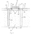
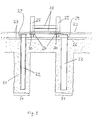
- FIG. 1 shows a vertical section through the device according to the invention.
- a non-reinforced mixed-in-place wall 21 are at a distance 16 support members 22 which protrude beyond the surface 26 of the mixed-in-place wall 21.
- a continuous head bar 23 made of concrete, which consists of a reinforcing cage 27 and are integrated in the connecting elements 24.
- columns 25 can be fastened non-positively to these connecting elements 24, between the dam beams 28 can be hung.
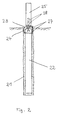
- Figure 2 shows a rotated by 90 ° to Figure 1 out, vertical section.
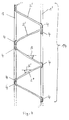
- FIGS. 3 to 5 show an embodiment variant according to the invention of mounting elements 14, from which the carrier elements 22 can be formed.
- Figures 6 to 8 show horizontal sections through the mixed-in-place wall 21, in which different trained support members 22 are set, which in turn consist of combinations of the mounting element 14.
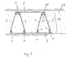
- FIG. 9 shows a variant in which the mixed-in-place wall 21 essentially consists of individual slots 31 for the carrier elements 22.
- Suitable foundation measures for such flood protection walls would be winkeising walls, secant bored pile walls, concrete slot walls or continuous sheet piling. Temporary protective walls could be securely fastened to these foundation measures.
- the invention therefore describes an economical as well as safe system with which temporary flood protection walls can be erected.
- the attachment of the temporary flood protection walls takes place in such a way that initially as a foundation and sealing wall unweighted mixed-in-place wall 21 is produced by the mixed-in-place process.
- the soil in question is converted into a soil mortar by one or more rod-shaped agitators or slit-wall cutter-like devices in the soil.
- water, binder and possibly additives or bentonite is added via the stirring tools or milling and mixed in this way the pending soil to a soil mortar.
- These support elements 22 are designed so that they can absorb vertical forces, horizontal forces and bending moments and can dissipate via the mixed-in-place wall 21 in the ground.
- carrier elements 22 it is preferred to use rolled carriers such as IPB carriers, double U carriers, tubes, sheet piles, bars, plates or combinations of these agents.
- prefabricated concrete columns or precast concrete piles are introduced into the slot filled with floor mortar, which have a free connection reinforcement on the air side.
- a particular variant of the invention is that for the support elements 22 mounting elements 14 and combinations of these mounting elements 14 are used ( Figure 3 to Figure 8).
- Such mounting elements 14 are particularly inexpensive compared to rolling beams and complicated welding devices.
- the elements 14 consist of substantially mutually parallel longitudinal bars 1, 1 ', 1 "..., which are non-positively connected by zig-zag or wavy arranged diagonal bars 2.
- a steel bar may be formed zigzag or wavy over a longer range ( Figure 3) or single diagonal bars 2 'or individual substantially triangular curved bars 2 "are used ( Figures 4 and 5).
- Static requirements may require that the longitudinal bars be connected to each other on two sides or through several layers of diagonal bars (Figure 8).
- welds 4 are preferably arranged in the arcs or tips of the diagonal bars 2 and the dimensions of the diagonal bars 2 are chosen so that the Longitudinal bars 1, 1 '... are as far outside as possible in the wall and thus larger bending moments can be absorbed.
- the inclination angles ⁇ , ⁇ ', with which the diagonal bars 2 run towards the longitudinal bars, are preferably in the range between 30 ° and 60 °.
- the diagonal bars 2 between the longitudinal bars 1, 1 ' should be as straight as possible.
- FIG. 5 shows a variant embodiment in which elements 14 are arranged triangular in relation to one another on the left side. On the right side, two elements 14 are combined to form a triangular element 19, in which a longitudinal bar 20 and longitudinal bars 1 'are non-positively and statically operatively welded to one another via two or more diagonal bars by welds 4, 4'. It may be expedient that in this case the size of the cross-sectional area of the longitudinal bar 20 is different than the cross-sectional area of the longitudinal bars 1 '.
- the longitudinal bars 1, 1 '... and the diagonal bars 2 are preferably made of profiled or ribbed structural steels with circular cross sections. In principle, however, all cross-sectional shapes are conceivable.
- the embodiment of the elements 14 can be made both of smooth steels, but preferably of steels, which have a certain roughness by mechanical processing or coating, which causes higher adhesive stresses in the floor mortar.
- each element 14 Preferably, only one earth-side bar 1 and one air-side bar 1 'are arranged on each element 14, whose cross-sectional areas can also vary.
- the later-mounted flood protection walls are higher, it may be expedient to equip the elements 14 with a plurality of longitudinal bars 1, 1 ', 1 "for static reasons (FIG. 8).
- the diagonal bars can also be welded between the longitudinal bars (FIG. 5).
- the elements 14 are preferably installed vertically and aligned so that their larger expanse area comes to lie across the plane of the mixed-in-place wall.
- angles ⁇ and ⁇ 'of these surfaces to the wall normal are preferably in a range between -45 ° and + 45 °.
- At least two or more elements 14 are combined with one another at the locations of the concentrated introduction of force.
- the elements 14 are introduced into the freshly prepared mortar only after preparation of the mixed-in-place wall 21, which is done by pure impressions or slight vibration, the elements 14 by suitable binding plates 3, 3 ', 5 in their arrangement to each other be fixed.
- the elements 14 are connected by constructive welds or by binding wire with the binding plates.
- the binding plates can also be replaced by rods.
- the binding plates 3, 3 ', 5 are arranged at intervals of about 0.5 to 2 m.
- the dimensions of the elements 14 are chosen to have sufficient steel coverage through the floor mortar within the mixed-in-place wall 21. It lies in the centimeter range.
- a reinforcing cage 27 is arranged in the head region 29 of the support elements 22, which connects the individual heads of the support elements 22 so that after concreting the head beam 23 vertical forces, horizontal forces, bending moments and Torsionsmomente of these can be included.
- the heads 29 of the support members 22, the reinforcement 27 and the connecting members 24 are concreted into the concrete of the head beam 23, the head beam concrete being substantially waterproofed to the surface 26 of the MIP wall.
- the reinforcing cage 27 is formed in the formation of the longitudinal bars and brackets so that it can transmit forces that are introduced to the connecting elements 24, via torsion in the heads 29 of the support elements 22.
- the connecting elements 24 are preferably made of screws, threaded sleeves, Absteckbolzen, Absteckhülsen or from bayonet-like elements, which are directly or indirectly connected with tension or pressure anchoring elements according to the state of anchoring technology, as they are known from the reinforced concrete composite construction.
- Such anchoring elements 30 are z. B. expansion anchor, Flachfußanker, Plattenfußanker or steel elements with holes through which rebars are pulled.
- the transmission takes place essentially via torsional forces in the head beam.
- the support elements 22 in turn direct the forces into the unreinforced mixed-in-place wall 21 and from there they are removed into the ground.
- An elaborate fastening technique of the connecting elements 24 is the dimensionally accurate direct or indirect welding of the connecting elements 24 to the reinforcing bars 7 of the head bar or to the connection reinforcement 29 of the carrier elements 22.
- the connecting elements 24 are sunk into the head bar 23 so that they can be protected in flood-free times by cover plates.
- the columns 25 are fastened with screws, nuts or bayonet-type connecting means frictionally to the connecting elements 24.
- the surface of the head bar at least partially smooth, flat and horizontal form.
- the upper edge of the head beam is preferably arranged level with the terrain.
- the mixed-in-place wall 21 can be made as a continuous wall or consist of individual slots 31 which are located only in areas where the support members 22 are provided.
- the slots 31 extend into greater depths, so that the horizontal forces can be removed from the water pressure in the ground.
- the foundation device according to the invention for transportable, temporary flood protection walls is an economical, inexpensive and equivalent solution.
Landscapes
- Engineering & Computer Science (AREA)
- Mining & Mineral Resources (AREA)
- Structural Engineering (AREA)
- Life Sciences & Earth Sciences (AREA)
- General Life Sciences & Earth Sciences (AREA)
- Paleontology (AREA)
- Civil Engineering (AREA)
- General Engineering & Computer Science (AREA)
- Revetment (AREA)
Applications Claiming Priority (1)
| Application Number | Priority Date | Filing Date | Title |
|---|---|---|---|
| DE200510013993 DE102005013993B3 (de) | 2005-03-26 | 2005-03-26 | Gründung für einen Hochwasserschutz |
Publications (2)
| Publication Number | Publication Date |
|---|---|
| EP1707685A2 true EP1707685A2 (fr) | 2006-10-04 |
| EP1707685A3 EP1707685A3 (fr) | 2007-10-17 |
Family
ID=36694999
Family Applications (1)
| Application Number | Title | Priority Date | Filing Date |
|---|---|---|---|
| EP06005787A Withdrawn EP1707685A3 (fr) | 2005-03-26 | 2006-03-21 | Structure de fondation de protection contre les crues |
Country Status (2)
| Country | Link |
|---|---|
| EP (1) | EP1707685A3 (fr) |
| DE (1) | DE102005013993B3 (fr) |
Cited By (4)
| Publication number | Priority date | Publication date | Assignee | Title |
|---|---|---|---|---|
| DE102006057811A1 (de) * | 2006-12-06 | 2008-06-19 | Franki Grundbau Gmbh & Co.Kg | Verfahren zur Herstellung einer Dichtwand mit Tragelementen aus Betonfertigteilen |
| DE102009021143A1 (de) * | 2009-05-13 | 2010-11-18 | Haus und Holzbau im Allgäu GmbH | Fundamentkorb, Fundament und Verfahren zur Bildung eines Fundaments |
| CN110029625A (zh) * | 2019-05-23 | 2019-07-19 | 中建科技(福州)有限公司 | 可拆卸易存储式防洪装置 |
| CN110344373A (zh) * | 2019-07-29 | 2019-10-18 | 中水淮河规划设计研究有限公司 | 一种堵头式橡胶坝不锈钢抗磨损衬板的安装方法 |
Family Cites Families (10)
| Publication number | Priority date | Publication date | Assignee | Title |
|---|---|---|---|---|
| JPH06257169A (ja) * | 1993-03-03 | 1994-09-13 | Kajima Corp | 小規模の地下室 |
| FR2736948B1 (fr) * | 1995-07-17 | 1997-08-14 | Sovran Jean Paul | Batardeau de rivage |
| DE19526396C2 (de) * | 1995-07-19 | 2000-11-02 | Dyckerhoff Ag | Baugrubenverbau, Verfahren zu seiner Herstellung sowie Baustoffgemenge dafür |
| DE29620193U1 (de) * | 1996-11-20 | 1997-02-06 | Heringhaus, Klaus, 58809 Neuenrade | Mobile Vorrichtung zum Schutz gegen Hochwasser |
| DE19949655A1 (de) * | 1998-10-15 | 2000-09-21 | Bilfinger Berger Bau | Kopfbalken für im Gelände stehende Wände |
| DE29823360U1 (de) * | 1998-12-22 | 1999-05-20 | Bauer Spezialtiefbau Gmbh, 86529 Schrobenhausen | Wasserdichte Flächenbewehrung in Schlitzwänden, Dichtwänden und Abdichtungswänden aus Mörtelsäulen nach dem "Mixed-in-Place"-Verfahren |
| KR20010043016A (ko) * | 1999-02-25 | 2001-05-25 | 메나르드-솔트레이트먼트 | 탄성 물질을 포함하는 콘크리트 및 그러한 콘크리트로만들어진 파일 |
| DE20107337U1 (de) * | 2001-04-27 | 2001-06-28 | Burger, Hans-Joachim, 93059 Regensburg | Hochwasser-Schutzvorrichtung |
| DE20203203U1 (de) * | 2002-02-28 | 2002-06-27 | Burger, Hans-Joachim, 93059 Regensburg | Durchsichtiger Hochwasserschutz |
| DE10238646B3 (de) * | 2002-08-23 | 2004-04-01 | Bauer Spezialtiefbau Gmbh | Dichte Mixed-in-Place-Wände |
-
2005
- 2005-03-26 DE DE200510013993 patent/DE102005013993B3/de not_active Expired - Fee Related
-
2006
- 2006-03-21 EP EP06005787A patent/EP1707685A3/fr not_active Withdrawn
Cited By (6)
| Publication number | Priority date | Publication date | Assignee | Title |
|---|---|---|---|---|
| DE102006057811A1 (de) * | 2006-12-06 | 2008-06-19 | Franki Grundbau Gmbh & Co.Kg | Verfahren zur Herstellung einer Dichtwand mit Tragelementen aus Betonfertigteilen |
| DE102009021143A1 (de) * | 2009-05-13 | 2010-11-18 | Haus und Holzbau im Allgäu GmbH | Fundamentkorb, Fundament und Verfahren zur Bildung eines Fundaments |
| CN110029625A (zh) * | 2019-05-23 | 2019-07-19 | 中建科技(福州)有限公司 | 可拆卸易存储式防洪装置 |
| CN110029625B (zh) * | 2019-05-23 | 2024-05-10 | 中建科技(福州)有限公司 | 可拆卸易存储式防洪装置 |
| CN110344373A (zh) * | 2019-07-29 | 2019-10-18 | 中水淮河规划设计研究有限公司 | 一种堵头式橡胶坝不锈钢抗磨损衬板的安装方法 |
| CN110344373B (zh) * | 2019-07-29 | 2024-02-20 | 中水淮河规划设计研究有限公司 | 一种堵头式橡胶坝不锈钢抗磨损衬板的安装方法 |
Also Published As
| Publication number | Publication date |
|---|---|
| DE102005013993B3 (de) | 2006-11-16 |
| EP1707685A3 (fr) | 2007-10-17 |
Similar Documents
| Publication | Publication Date | Title |
|---|---|---|
| DE69611931T2 (de) | Unterirdisches bauwerk, insbesondere für die herstellung von tunnels, unterführungen, tiefgaragen, etc. und sein herstellungsverfahren | |
| CH707671B1 (de) | Stützmauerelement und Stützmauer aus Stützmauerelementen. | |
| AT391506B (de) | Vorrichtung zur abfuehrung von waerme in den erdboden bzw. zur aufnahme der waerme aus dem erdboden | |
| DE68912648T2 (de) | Bauverfahren. | |
| DE102005013993B3 (de) | Gründung für einen Hochwasserschutz | |
| DE2917994C2 (de) | Verfahren zur Herstellung einer Baugrubenverbau- oder Stützwand aus Stahlbeton für Geländeeinschnitte | |
| DE1634589B2 (de) | Pfahlrost aus betonpfaehlen | |
| EP2803786B1 (fr) | Dispositif de montage et de réparation | |
| DE19547911C2 (de) | Mit Spundbohlen erstellte Spundwand mit einer Gurtung | |
| DE102005013994B4 (de) | Vorrichtung zur konzentrierten Krafteinleitung in unbewehrte Schlitzwände im Erdreich | |
| DE102014118543B4 (de) | Abgrenzungsanordnung | |
| CH711288B1 (de) | Wasserdurchlässige Stützkonstruktion, insbesondere zur Böschungsstabilisierung sowie zur Terrassierung und Terraingestaltung. | |
| DE20308083U1 (de) | Hochwasser-Schutzsystem | |
| EP0922810B1 (fr) | Procédé pour la stabilisation d'une pente | |
| DE4445707A1 (de) | Verfahren zur schnelleren, rationelleren und umweltfreundlicheren Herstellung nicht höhengleicher Kreuzungen von Verkehrswegen und von Stützbauwerken entlang vorhandener Verkehrswege | |
| DE102005010495B4 (de) | Vorrichtung, daraus gebildeter Damm und Verfahren zur Herstellung eines Dammes | |
| EP1964978B1 (fr) | Procédé d'établissement d'une installation de quai et installation de quai | |
| DE711114C (de) | Verfahren zur Herstellung von im Gundwasser oder im offenen Wasser liegenden Bauwerken in aufgeloester Bauweise | |
| DE1634589C3 (de) | Pfahlrost aus Betonpfählen | |
| DE3002739A1 (de) | Durch wasserdurchlaessige konstruktionen begrenztes bauwerk, insbesondere becken, z.b. fluessigkeitsspeicherbecken, schwimmbecken o.ae. | |
| DE4220746A1 (de) | Verfahren und Einrichtung für den Schutz von Ufern und Unterwasserböschungen | |
| AT388008B (de) | Verfahren zur errichtung eines stauwerkes fuer laufkraftwerke und mit dem verfahren hergestelltes stauwerk | |
| DE2706665A1 (de) | Sperrwand | |
| EP0383791A1 (fr) | Support de coffrage | |
| DE4104045A1 (de) | Verfahren zur herstellung einer begruenbaren, universellen stuetzwandkonstruktion aus stahlbetonfertigteilen zur stabilisierung von gelaendespruengen |
Legal Events
| Date | Code | Title | Description |
|---|---|---|---|
| PUAI | Public reference made under article 153(3) epc to a published international application that has entered the european phase |
Free format text: ORIGINAL CODE: 0009012 |
|
| AK | Designated contracting states |
Kind code of ref document: A2 Designated state(s): AT BE BG CH CY CZ DE DK EE ES FI FR GB GR HU IE IS IT LI LT LU LV MC NL PL PT RO SE SI SK TR |
|
| AX | Request for extension of the european patent |
Extension state: AL BA HR MK YU |
|
| PUAL | Search report despatched |
Free format text: ORIGINAL CODE: 0009013 |
|
| AK | Designated contracting states |
Kind code of ref document: A3 Designated state(s): AT BE BG CH CY CZ DE DK EE ES FI FR GB GR HU IE IS IT LI LT LU LV MC NL PL PT RO SE SI SK TR |
|
| AX | Request for extension of the european patent |
Extension state: AL BA HR MK YU |
|
| RIC1 | Information provided on ipc code assigned before grant |
Ipc: E02B 3/10 20060101ALI20070910BHEP Ipc: E02D 5/18 20060101ALI20070910BHEP Ipc: E02D 3/12 20060101ALI20070910BHEP Ipc: E02D 27/12 20060101AFI20060802BHEP |
|
| AKX | Designation fees paid | ||
| STAA | Information on the status of an ep patent application or granted ep patent |
Free format text: STATUS: THE APPLICATION IS DEEMED TO BE WITHDRAWN |
|
| 18D | Application deemed to be withdrawn |
Effective date: 20080418 |
|
| REG | Reference to a national code |
Ref country code: DE Ref legal event code: 8566 |