EP1707714A2 - Verrouillage d'urgence pour une porte coupe-feu et dispositif de déverrouillage pour un volet d'extracteur de fumée - Google Patents
Verrouillage d'urgence pour une porte coupe-feu et dispositif de déverrouillage pour un volet d'extracteur de fumée Download PDFInfo
- Publication number
- EP1707714A2 EP1707714A2 EP06004164A EP06004164A EP1707714A2 EP 1707714 A2 EP1707714 A2 EP 1707714A2 EP 06004164 A EP06004164 A EP 06004164A EP 06004164 A EP06004164 A EP 06004164A EP 1707714 A2 EP1707714 A2 EP 1707714A2
- Authority
- EP
- European Patent Office
- Prior art keywords
- temperature
- latch
- active agent
- fire
- bolt
- Prior art date
- Legal status (The legal status is an assumption and is not a legal conclusion. Google has not performed a legal analysis and makes no representation as to the accuracy of the status listed.)
- Withdrawn
Links
Images




Classifications
-
- E—FIXED CONSTRUCTIONS
- E05—LOCKS; KEYS; WINDOW OR DOOR FITTINGS; SAFES
- E05B—LOCKS; ACCESSORIES THEREFOR; HANDCUFFS
- E05B65/00—Locks or fastenings for special use
- E05B65/10—Locks or fastenings for special use for panic or emergency doors
- E05B65/104—Locks or fastenings for special use for panic or emergency doors actuated in response to heat, e.g. with fusible element, bimetal, memory shape or swelling material
-
- E—FIXED CONSTRUCTIONS
- E06—DOORS, WINDOWS, SHUTTERS, OR ROLLER BLINDS IN GENERAL; LADDERS
- E06B—FIXED OR MOVABLE CLOSURES FOR OPENINGS IN BUILDINGS, VEHICLES, FENCES OR LIKE ENCLOSURES IN GENERAL, e.g. DOORS, WINDOWS, BLINDS, GATES
- E06B5/00—Doors, windows, or like closures for special purposes; Border constructions therefor
- E06B5/10—Doors, windows, or like closures for special purposes; Border constructions therefor for protection against air-raid or other war-like action; for other protective purposes
- E06B5/16—Fireproof doors or similar closures; Adaptations of fixed constructions therefor
- E06B5/164—Sealing arrangements between the door or window and its frame, e.g. intumescent seals specially adapted therefor
Definitions
- this object is achieved in that the emergency lock for a fire door or the smoke flap contains a bolt and a temperature-active means for locking operation.
- the fire door is locked to the frame and / or the floor area, wherein the bolt but only in case of fire, and then automatically, is extended by the temperature-active agent.
- the temperature-active agent is a bimetallic spring.
- a bimetallic spring consists of two firmly interconnected parts of metals or metal alloys with different coefficients of expansion. When the temperature changes, the two parts change their extent differently. This difference creates a change in shape and / or length.
- the design in which the temperature-active material goes back to its original state when cooled has the advantage that the door in question can be reopened after cooling with extinguishing water, and rescue and extinguishing forces access.
- the triggering device is a detector device and / or a switch.
- the detector device may be, for example, a smoke detector which automatically emits a corresponding signal to the electrochemical actuator when a fire is detected. This then actuates the bolt.
- the switch may be, for example, an emergency switch, which is provided in the immediate vicinity of the fire door. Once a fire is detected, the emergency switch can be operated by one person. Furthermore, the fire door can be locked even in the presence of other sources of danger, such as water ingress, toxic gases, etc. Also, a lock may take place in the event of a break-in, wherein the detector device is then designed as a burglary detector, for example IR light barrier, general person detector, glass breakage detector, etc.
- FIGS. 1a and 1b each show an emergency lock 10 of a fire door (not shown) in the normal case and under the action of heat.
- the emergency lock 10 has a latch 14 which is mounted in a blind hole in the fire door.
- the blind hole is here formed by a hollow cylindrical sleeve body 12 with closed bottom 13, in which the designed as a round bolt latch 14 is mounted longitudinally displaceable, wherein the latch 14 occupies the open cross-section of the sleeve body 12 and the sleeve body 12 serves as a bolt guide.
- the bolt may also be designed as a pivot bolt.
- a temperature-active means 16 is introduced between the one end face of the bolt 14 and the bottom 13 of the sleeve body 12.
- a temperature-active Means 16 in the compressed state.
- the term "normal state” here means a state within a normal temperature range. In this state, the front end of the bolt 14 is flush with the front end of the sleeve body 12.
- the emergency lock 10 may be installed in the fold of a door leaf, in a frame or in the floor area of the fire door. For mounting only the attachment of a blind hole in the door or in the frame is required. For fastening, the sleeve body has a flange 11 with screw holes 15 at its open end. In the normal state, the emergency lock 10 does not provide any locking function.
- the emergency lock 10 is mounted in such a way that it is normally flush with the mounting surface.
- FIG. 1 b shows the emergency lock 10 when exposed to heat.
- the term "heat exposure” in this case means the presence of a fire in the immediate vicinity of the fire door. In this case, temperatures of above 100 ° C are present. In this heat, the temperature-active agent 16 expands within the sleeve body 12, whereby the bolt 14 is pushed a little way out of the sleeve body 12. In this case, the front end of the bolt 14 moves into a bolt receptacle, not shown, and thus locks the fire door.
- an intumescent material 16 is used in this embodiment, which expands when exposed to heat.
- an intumescent material should be used which expands at a temperature greater than 100 ° C.
- FIGS. 2a and 2b show an emergency interlock 10 in the normal case and under the effect of heat.
- This emergency lock 10 in turn has latch 14 a sleeve body 12. Identical parts are provided with the same reference numerals as in the emergency lock 10 described above.
- the emergency latch 10 includes a temperature-responsive means which is a helical bimetallic spring 18 interposed between the bottom 13 of the sleeve body 12 and the latch 14.
- the bimetal spring 18 When exposed to heat (see Figure 2b), the bimetal spring 18 is in the expanded state, whereby it pushes the latch 14 a little way from the sleeve body 12.
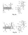
- FIGS. 3a and 3b show an emergency interlock 10, in each case under normal conditions and under the action of heat.
- This emergency lock 10 in turn has a latch 14 and a sleeve body 12. Identical parts are provided with the same reference numerals as in the emergency lock 10 described above.
- the emergency lock 10 contains as a temperature-active means a shape memory spring 20, which is designed here as a three-legged leaf spring.
- the leaf spring has two outer legs 19 and an intermediate inner leg 21, which are connected at their base. Normally, the outer legs 19 and the inner leg 21 lie in one plane. When exposed to temperature, the outer leg 19 and the inner leg 21 spread V-shaped. If a two-way shape memory spring is used, they will return to their original shape when cooled.
- the free ends of the shape-memory spring 20 are inserted via an opening 23 in the cylinder jacket of the sleeve body 20 between the bottom 13 of the sleeve body 12 and the bolt 14.
- the shape-memory spring 20 is compressed and the front end of the bolt 14 ends flush with the front end of the sleeve body 12.
- FIGS. 4a and 4b each show a further embodiment of an emergency lock 10 for a lock in the normal case (FIG. 4a) and under the action of heat (FIG. 4b).
- a lock bolt 14 is formed as a two-part, rectangular flat bolt. It comprises a locking shaft 6 which cooperates via a toothing 7 with a lock mechanism (not shown) for locking operation.
- a main bolt 8 is formed on which a telescopically a bolt extension 9 is slidably mounted along the bolt path.
- the bolt extension 9 is guided in the manner of a cap on the tapered free end 5 of the main bolt 8.
- the bolt extension 9 forms a sleeve body 12 'around the tapered end 5 of the main bolt 8.
- a temperature-active means is arranged between the base 13 of the bolt extension 9 and the end face of the tapered end 5, a temperature-active means is arranged.
- an intumescent material 16 is also used in this embodiment, which expands when exposed to heat.
- an intumescent material should be used which expands at a temperature greater than 100 ° C.
- the automatic locking of the lock bolt can be designed in conjunction with intumescent material, whereby a temperature-controlled self-locking lock is constructed.
- the advantage here is that when locked fire door, i. when the main bolt 8, the bolt extension 9 is actuated, the main bolt 8 receives the bias and thus can extend the bolt extension 9 vortempos arthritis.
- FIGS. 5a and 5b each show a further embodiment of an emergency lock 10 in the normal case (FIG. 5a) and under the action of heat (FIG. 5b).
- the emergency lock 10 further comprises a snap closure 22, which comprises the latch 14 and a snap receptacle 24 designed to receive the latch 14.
- the snap-action receptacle 24 is resiliently mounted in such a way that it can cover the maximum distance between A and B shown in FIG. 5a.
- the latch 14 has at its end two sliding bevels 25, which cooperate with the snap-action receptacle 26.
- the springs 26 shown schematically in the figure are in the relaxed state, and the snap receptacle 24 is located at the position A. If the door is closed, the outwardly tapered latch 14 abuts the outer edge of the snap receptacle 24. In a further closure of the door then the spring-loaded snap-action receptacle 24 is pushed away so far outward until the tip of the bolt 14 runs along the outer surface of the snap-action receptacle 24 (position B). The diagrammatically illustrated springs are maximally compressed at this position.
- the latch 14 engages in the opening of the snap-action receptacle 24.
- the springs of the snap receptacle 24 are relaxed again (position A), and the door is kept closed.
- the door is unlocked in this state and can be opened again at any time.
- the intumescent material 16 inserted in the sleeve body 12 expands, so that the latch 14 is pushed out of the sleeve body 12 to some extent (see FIG. 5 b).
- the latch 14 compresses the springs of the snap-action receptacle 24 (position B). Arrived at this position, the springs can not be further compressed, so that the door can not be opened by a simple force.
Landscapes
- Business, Economics & Management (AREA)
- Emergency Management (AREA)
- Special Wing (AREA)
Applications Claiming Priority (1)
| Application Number | Priority Date | Filing Date | Title |
|---|---|---|---|
| DE200510009996 DE102005009996A1 (de) | 2005-03-06 | 2005-03-06 | Notverriegelung für eine Brandschutztür und Entriegelung für eine Brandschutzklappe |
Publications (2)
| Publication Number | Publication Date |
|---|---|
| EP1707714A2 true EP1707714A2 (fr) | 2006-10-04 |
| EP1707714A3 EP1707714A3 (fr) | 2006-11-02 |
Family
ID=36463534
Family Applications (1)
| Application Number | Title | Priority Date | Filing Date |
|---|---|---|---|
| EP06004164A Withdrawn EP1707714A3 (fr) | 2005-03-06 | 2006-03-01 | Verrouillage d'urgence pour une porte coupe-feu et dispositif de déverrouillage pour un volet d'extracteur de fumée |
Country Status (3)
| Country | Link |
|---|---|
| EP (1) | EP1707714A3 (fr) |
| CA (1) | CA2538437A1 (fr) |
| DE (1) | DE102005009996A1 (fr) |
Cited By (6)
| Publication number | Priority date | Publication date | Assignee | Title |
|---|---|---|---|---|
| EP2224090A2 (fr) | 2009-02-27 | 2010-09-01 | Stöbich Brandschutz GmbH | Dispositif de fermeture coupe-feu |
| CN102220829A (zh) * | 2011-06-09 | 2011-10-19 | 支亮 | 一种防火门 |
| WO2013119795A1 (fr) * | 2012-02-10 | 2013-08-15 | Illinois Tool Works Inc. | Verrou de porte de sèche-linge actionné thermiquement |
| CN107084413A (zh) * | 2017-04-07 | 2017-08-22 | 中国航天建设集团有限公司 | 带有主动灭火装置的吸油烟机 |
| CN107080915A (zh) * | 2017-04-07 | 2017-08-22 | 中国航天建设集团有限公司 | 主动灭火装置 |
| CN111395894A (zh) * | 2020-04-30 | 2020-07-10 | 广州铸安机电设备有限公司 | 一种锁止机构及温感门窗闭合装置 |
Families Citing this family (4)
| Publication number | Priority date | Publication date | Assignee | Title |
|---|---|---|---|---|
| LT5871B (lt) * | 2012-01-06 | 2012-09-25 | Remigijus Guobys | Terminis durų spynos kaištis |
| US8979143B1 (en) * | 2013-09-25 | 2015-03-17 | I-Tek Metal Mfg. Co., Ltd. | Fire bolt assembly for a door |
| ES2908343T3 (es) * | 2017-12-21 | 2022-04-28 | Trine Access Tech | Cerradura de puerta de accionamiento eléctrico con elemento termosensible |
| US20220074235A1 (en) * | 2020-09-05 | 2022-03-10 | Ryan Joongi Cho | Automatic door opening device using thermal expansion of shape memory alloy |
Family Cites Families (13)
| Publication number | Priority date | Publication date | Assignee | Title |
|---|---|---|---|---|
| DE7626523U1 (de) * | 1976-08-25 | 1981-02-05 | 8890 Aichach | Feuerschutztuer |
| DE3239177A1 (de) * | 1982-10-22 | 1984-05-03 | Dictator Technik - Ruef & Co, 8902 Neusäß | Feuerschutztuere |
| DE3523585A1 (de) * | 1985-07-02 | 1987-01-15 | Dieter Beikirch | Vorrichtung zum ausloesen von oeffnungseinrichtungen fuer lichtkuppeln, rauchabzugsklappen oder dergl. |
| US5121950A (en) * | 1991-04-23 | 1992-06-16 | The Stanley Works | Heat activated spring loaded locking bolt for hinged doors and door assemblies employing same |
| FR2686856B1 (fr) * | 1992-02-03 | 1994-03-18 | Messier Bugatti | Dispositif d'accrochage assurant le verrouillage, en position train haut, d'un train d'atterrissage d'avion. |
| US5380053A (en) * | 1993-07-26 | 1995-01-10 | F. L. Saino Manufacturing Co. | Intumescent fire door lock mechanism |
| GB2289497B (en) * | 1994-05-17 | 1998-03-04 | Lorient Polyprod Ltd | Lock and seal assembly |
| DE19601230C2 (de) * | 1996-01-15 | 2002-03-21 | Zangenstein Elektro | Türverriegelung |
| GB2321492A (en) * | 1997-01-22 | 1998-07-29 | Anthony Elworthy | Thermally actuated bolt |
| DE19801752C1 (de) * | 1998-01-20 | 1999-05-12 | Dorma Gmbh & Co Kg | Verriegelungseinrichtung für Notausgangstüren |
| DE10007552A1 (de) * | 2000-02-18 | 2001-09-06 | Esco Metallbaubeschlag Handel Gmbh | Verriegelung für Brandschutzkonstruktionen |
| DE20012996U1 (de) * | 2000-07-27 | 2000-11-02 | Promat GmbH, 40878 Ratingen | Brandschutztür |
| DE10321802B4 (de) * | 2003-05-14 | 2012-09-13 | Dorma Gmbh + Co. Kg | Sicherungsvorrichtung für eine Tür, insbesondere Feuerschutztür oder dergleichen |
-
2005
- 2005-03-06 DE DE200510009996 patent/DE102005009996A1/de not_active Ceased
-
2006
- 2006-03-01 EP EP06004164A patent/EP1707714A3/fr not_active Withdrawn
- 2006-03-03 CA CA 2538437 patent/CA2538437A1/fr not_active Abandoned
Cited By (8)
| Publication number | Priority date | Publication date | Assignee | Title |
|---|---|---|---|---|
| EP2224090A2 (fr) | 2009-02-27 | 2010-09-01 | Stöbich Brandschutz GmbH | Dispositif de fermeture coupe-feu |
| DE102009010924A1 (de) * | 2009-02-27 | 2010-09-09 | Stöbich Brandschutz GmbH | Feuerhemmende Verschlussvorrichtung |
| CN102220829A (zh) * | 2011-06-09 | 2011-10-19 | 支亮 | 一种防火门 |
| WO2013119795A1 (fr) * | 2012-02-10 | 2013-08-15 | Illinois Tool Works Inc. | Verrou de porte de sèche-linge actionné thermiquement |
| US10612274B2 (en) | 2012-02-10 | 2020-04-07 | Illinois Tool Works Inc. | Thermally actuated dryer door lock |
| CN107084413A (zh) * | 2017-04-07 | 2017-08-22 | 中国航天建设集团有限公司 | 带有主动灭火装置的吸油烟机 |
| CN107080915A (zh) * | 2017-04-07 | 2017-08-22 | 中国航天建设集团有限公司 | 主动灭火装置 |
| CN111395894A (zh) * | 2020-04-30 | 2020-07-10 | 广州铸安机电设备有限公司 | 一种锁止机构及温感门窗闭合装置 |
Also Published As
| Publication number | Publication date |
|---|---|
| CA2538437A1 (fr) | 2006-09-06 |
| EP1707714A3 (fr) | 2006-11-02 |
| DE102005009996A1 (de) | 2006-09-14 |
Similar Documents
| Publication | Publication Date | Title |
|---|---|---|
| DE2611359A1 (de) | Treibstangenverschluss, insbesondere fuer zweifluegelige feuerschutztueren | |
| DE3239177A1 (de) | Feuerschutztuere | |
| EP1707714A2 (fr) | Verrouillage d'urgence pour une porte coupe-feu et dispositif de déverrouillage pour un volet d'extracteur de fumée | |
| EP2840223B1 (fr) | Volet roulant, rideau pare-feu et volet roulant coupe-feu | |
| EP1703067A2 (fr) | Porte coupe-feu et coupe-fumée pour fermer des ouvertures de portes | |
| EP0831442B1 (fr) | Dispositif de sécurité contre l'effraction | |
| EP1671291B1 (fr) | Utilisation d'un materiau intumescent, et dispositif comprenant un tel materiau | |
| DE102005009995B4 (de) | Sperr-/Freigabevorrichtung für eine Schwenkfalle eines Türöffners | |
| AT403498B (de) | Fixiereinrichtung für brandschutztüren | |
| DE19964251A1 (de) | Tür mit Türschließvorrichtung | |
| EP3492684B1 (fr) | Bascule de déclenchement pour un dispositif d'étanchéité d'une porte pivotante | |
| DE3241846C2 (fr) | ||
| EP3702556B1 (fr) | Serrure à loquet, de préférence serrure à loquet à rouleau, avec un dispositif d'actionnement | |
| EP3187671A1 (fr) | Dispositif de verrouillage en tant que sécurité anti-effraction pour par exemple des fenêtres et des portes | |
| DE102009031490A1 (de) | Schließfolgeregelung | |
| DE102019001721B4 (de) | Schließvorrichtung | |
| DE3417054A1 (de) | Treibstangenverschluss fuer den standfluegel von zweifluegeligen tueren, insbesondere selbsttaetig schliessenden feuerschutztueren | |
| DE10007552A1 (de) | Verriegelung für Brandschutzkonstruktionen | |
| DE2919951A1 (de) | Vorrichtung zum dichthalten einer feuerschutztuer | |
| EP2787160B1 (fr) | Joint de verrou et système de joint doté de celui-ci | |
| DE20207974U1 (de) | Türverriegelungsvorrichtung für Türelemente von feuerbeständigen Trennwandsystemen | |
| EP4332341B1 (fr) | Joint pour une porte ou une fenêtre avec une baguette d'étanchéité pouvant être abaissé automatiquement lors de la fermeture de la porte ou de la fenêtre | |
| DE102020203078B4 (de) | Schiebetüranlage | |
| DE102006012093A1 (de) | Feuer- und Rauchschutztür zum Verschließen von Türöffnungen | |
| EP0782657B1 (fr) | Porte coupe-feu |
Legal Events
| Date | Code | Title | Description |
|---|---|---|---|
| PUAI | Public reference made under article 153(3) epc to a published international application that has entered the european phase |
Free format text: ORIGINAL CODE: 0009012 |
|
| PUAL | Search report despatched |
Free format text: ORIGINAL CODE: 0009013 |
|
| AK | Designated contracting states |
Kind code of ref document: A2 Designated state(s): AT BE BG CH CY CZ DE DK EE ES FI FR GB GR HU IE IS IT LI LT LU LV MC NL PL PT RO SE SI SK TR |
|
| AX | Request for extension of the european patent |
Extension state: AL BA HR MK YU |
|
| AK | Designated contracting states |
Kind code of ref document: A3 Designated state(s): AT BE BG CH CY CZ DE DK EE ES FI FR GB GR HU IE IS IT LI LT LU LV MC NL PL PT RO SE SI SK TR |
|
| AX | Request for extension of the european patent |
Extension state: AL BA HR MK YU |
|
| AKX | Designation fees paid | ||
| STAA | Information on the status of an ep patent application or granted ep patent |
Free format text: STATUS: THE APPLICATION IS DEEMED TO BE WITHDRAWN |
|
| 18D | Application deemed to be withdrawn |
Effective date: 20070503 |
|
| REG | Reference to a national code |
Ref country code: DE Ref legal event code: 8566 |