EP1707720A1 - Kippfenstereinheit - Google Patents
Kippfenstereinheit Download PDFInfo
- Publication number
- EP1707720A1 EP1707720A1 EP06110836A EP06110836A EP1707720A1 EP 1707720 A1 EP1707720 A1 EP 1707720A1 EP 06110836 A EP06110836 A EP 06110836A EP 06110836 A EP06110836 A EP 06110836A EP 1707720 A1 EP1707720 A1 EP 1707720A1
- Authority
- EP
- European Patent Office
- Prior art keywords
- crosspiece
- mobile
- window unit
- unit according
- frame
- Prior art date
- Legal status (The legal status is an assumption and is not a legal conclusion. Google has not performed a legal analysis and makes no representation as to the accuracy of the status listed.)
- Granted
Links
- 230000005484 gravity Effects 0.000 description 1
- 230000037431 insertion Effects 0.000 description 1
- 238000003780 insertion Methods 0.000 description 1
- 238000009413 insulation Methods 0.000 description 1
- 230000001788 irregular Effects 0.000 description 1
- 239000000463 material Substances 0.000 description 1
- 239000002184 metal Substances 0.000 description 1
- 239000002023 wood Substances 0.000 description 1
Images



Classifications
-
- E—FIXED CONSTRUCTIONS
- E05—LOCKS; KEYS; WINDOW OR DOOR FITTINGS; SAFES
- E05C—BOLTS OR FASTENING DEVICES FOR WINGS, SPECIALLY FOR DOORS OR WINDOWS
- E05C9/00—Arrangements of simultaneously actuated bolts or other securing devices at well-separated positions on the same wing
- E05C9/002—Arrangements of simultaneously actuated bolts or other securing devices at well-separated positions on the same wing with arrangements allowing the wing to be slam-shut, e.g. by securing elements with latching action
-
- E—FIXED CONSTRUCTIONS
- E05—LOCKS; KEYS; WINDOW OR DOOR FITTINGS; SAFES
- E05C—BOLTS OR FASTENING DEVICES FOR WINGS, SPECIALLY FOR DOORS OR WINDOWS
- E05C9/00—Arrangements of simultaneously actuated bolts or other securing devices at well-separated positions on the same wing
- E05C9/18—Details of fastening means or of fixed retaining means for the ends of bars
- E05C9/1808—Keepers
-
- E—FIXED CONSTRUCTIONS
- E05—LOCKS; KEYS; WINDOW OR DOOR FITTINGS; SAFES
- E05C—BOLTS OR FASTENING DEVICES FOR WINGS, SPECIALLY FOR DOORS OR WINDOWS
- E05C9/00—Arrangements of simultaneously actuated bolts or other securing devices at well-separated positions on the same wing
- E05C9/02—Arrangements of simultaneously actuated bolts or other securing devices at well-separated positions on the same wing with one sliding bar for fastening when moved in one direction and unfastening when moved in opposite direction; with two sliding bars moved in the same direction when fastening or unfastening
-
- E—FIXED CONSTRUCTIONS
- E05—LOCKS; KEYS; WINDOW OR DOOR FITTINGS; SAFES
- E05C—BOLTS OR FASTENING DEVICES FOR WINGS, SPECIALLY FOR DOORS OR WINDOWS
- E05C9/00—Arrangements of simultaneously actuated bolts or other securing devices at well-separated positions on the same wing
- E05C9/18—Details of fastening means or of fixed retaining means for the ends of bars
- E05C9/1825—Fastening means
- E05C9/1833—Fastening means performing sliding movements
- E05C9/185—Fastening means performing sliding movements parallel with actuating bar
Definitions
- This invention relates to a bottom-hung window unit, in particular a bottom-hung window unit whose frame is made of metal, PVC or similar materials, wood - PVC, etc.
- bottom-hung windows are used extensively because they meet a wide range of requirements in buildings of all kinds (residential, schools, hospitals, factories and so on).
- Windows of this kind are installed in the parts of a building that are not easy to reach as, for example, is the case of transom windows or fanlights (usually above a door) or that are situated very high up (as, for example, in factory buildings) and are opened preferably using a suitable operator or other tool with hooking means at its top end.
- a window of this kind has two hinge points between the mobile frame and the fixed frame on the bottom horizontal edge and a single point by which the mobile frame is closed, on the top horizontal edge.
- the single closing point which is usually located half way along the width of the window frame, consists of a well known device which those familiar with the trade refer to as "latch".
- the latch is basically a fastening element, consisting of a pin mounted on suitable supporting means (plates) attached to the mobile frame, and a striker element attached to the fixed frame.
- the striker element (usually an inclined surface) is normally coaxial with the latch pin which can slide axially (in both directions, thanks to a spring) towards an engagement slot located at the innermost end of the striker element.
- the outermost end of the latch has a ring handle that can be operated by hand or engaged by a hook or operator.
- the user can release the latch pin from the engagement slot so that gravity causes the mobile frame to be tilted towards the inside of the room where it is installed.
- the user pushes the mobile frame towards the fixed frame until the pin springs into the slot.
- the single closing point makes it difficult to close the window satisfactorily because, amongst other things, windows of this kind usually have irregular proportions (very wide and low, very narrow and tall, depending on requirements) and thus the single closing point, which is usually positioned, as mentioned above, half way along the window, cannot provide an efficient seal or sufficient guarantee of security for the entire window.
- the single closing point offers little resistance to would-be burglars and applies insufficient pressure on the weather strips, especially at the corners furthest away from it, providing an ineffective seal against rain and/or draughts (as well as low insulation against noise).
- the aim of this invention is to overcome the above mentioned disadvantages by providing an operating device for opening and closing bottom-hung windows which is extremely versatile and can be mounted on bottom-hung windows of any kind and size and which offers a high level of security, an effective weather seal and ease of operation when opening and closing the window.
- a bottom-hung window unit comprising at least: a mobile frame and a fixed frame hinged to each other along a respective first crosspiece; drive means acting between a second crosspiece, parallel and opposite to the first crosspiece, on which the mobile frame is hinged to the fixed frame, said drive means being designed to enable the window to be moved to an open configuration, where the second, mobile crosspiece is away from the respective second, fixed crosspiece, and a closed configuration, where the mobile crosspiece is in contact with the fixed crosspiece;
- the drive means comprise operating means located on the mobile crosspiece and having at least two elements for closing the mobile frame against the fixed frame, these elements being spaced far apart and being able to be securely coupled to each other by means of strikers located on the fixed crosspiece; suitable means act on the operating means and, by operating on the mobile frame, enable the window unit to be automatically switched from the open to the closed configuration.
- the window unit according to the invention is of the bottom-hung type.
- This type of window unit basically comprises a mobile frame 2 and a fixed frame 3 hinged to each other, at 3i, by a pair of customary hinge bodies, along a respective first crosspiece 4 and drive means 5 for opening and closing the window unit 1.
- the mobile frame 2 and the fixed frame 3 each have respective longitudinal grooves C2 and C3 in which operating accessories can be fastened.
- the drive means 5 act between a second crosspiece 6a and 6b, parallel and opposite the first crosspiece 4 on which the mobile frame 2 is hinged to the fixed frame 3.
- the drive means 5 enable the window to be moved between an open configuration, where the second crosspiece 6a of the mobile frame 2 is away from the respective second crosspiece 6b of the fixed frame 3 (that is to say, where the mobile frame is tilted towards the inside of the room relative to the fixed frame 3) and a closed configuration where the mobile crosspiece 6a is in contact with the fixed crosspiece 6b (see arrow F2, Figure 2).
- the open position at a predetermined angle is attained by a stay rod, labelled 2t and not described in further detail because it is of well known type.
- the drive means 5 at least comprise operating means 7 located on the mobile crosspiece 6a and having at least two elements 8 and 9 for closing the mobile frame 2 against the fixed frame 3.
- the closing elements 8 and 9 are spaced far apart and can be securely coupled to each other by means of strikers 10a and 10b located on the crosspiece 6b of the fixed frame 3.
- means 11 are provided to act on the operating means 7 to actuate the mobile frame 2 in such a way that the window 1 is moved automatically from the open to the closed configuration.
- the aforementioned closing elements 8 and 9 are preferably, but not necessarily, equally spaced from a central point on the mobile crosspiece 6a.
- the two closing elements 8 and 9 may be positioned in the vicinity of the respective corner zones of the mobile crosspiece 6a.
- the drive means 5 further comprise an actuating element 12 located on the outside of the mobile crosspiece 6a and acting on the operating means 7 in such a way as to enable the operating means 7 at least to switch from the closed to the open configuration.
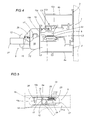
- the actuating element consists of a lever or handle 12 that rotates about an axis perpendicular to the plane of the mobile frame and associated with a spindle 15 housed in a respective covering element 16 associated with the outside of the mobile crosspiece 6a.
- the spindle 15 has a radially protruding pin 17 that engages a recess 18 made in a first operating portion 19a of a slider 19 for moving a drive rod 7a located in the mobile crosspiece 6a.
- a second operating portion 19b of the slider 19 extends into the mobile crosspiece 6a through a slot 20 made in the mobile crosspiece 6a itself; in use, the second, internal operating portion 19b is interposed between two contact elements or bosses 21 and 22 located on the rod 7a (see Figure 6 ) and in such a way as to enable the rod 7a itself to be actuated in both directions, corresponding to the closed and open configurations of the mobile frame 2 (see arrows F7a).
- the operating means 7 comprise the aforementioned drive rod 7a, which is slidably accommodated in the groove C2 in the mobile crosspiece 6a.
- the drive rod 7a is associated with vertically protruding bosses 8 and 9 constituting the aforementioned closing elements.
- the aforementioned automatic switch means 11 comprise return means 13 and cam means 14 located in the vicinity of the two strikers 10a and 10b.
- the return means 13 act on the lever or handle 12 in such a way as to move the lever 12 back into the window closed configuration when no force is applied to the lever 12 itself (see arrows F12, Figure 5).
- the return means consist of a spring 13 interposed between the first, operating portion 19a of the slider 19 and a fixed contact element 23 protruding perpendicularly from the mobile crosspiece 6a on a mounting plate 24 attached to the mobile crosspiece 6a itself.
- the aforementioned cam means 14 are located, as stated, in the vicinity of the two strikers 10a and 10b and operate on the respective bosses 8 and 9 in such a way as to cause:
- the strikers may consist of at least two blocks 10a, 10b positioned on and attached to the fixed crosspiece 6b at the respective longitudinal groove C3 (through customary contact counterplates 10c acting between the groove C3 and the respective block 10a, 10b).
- Each block 10a and 10b has a half slot 25, open on the inside of the mobile crosspiece 6b, for securely engaging a respective boss 8 and 9 in such a way as to define the aforementioned closed configuration.
- each block 10a and 10b has a first surface 14, facing the mobile crosspiece 6a, with an inclined profile, for striking the respective boss 8 and 9, and, in practice, constituting the aforementioned cam means.
- each half slot recess 25 has a second profile 26 for coming into contact with the respective boss 8, 9 and inclined in the direction opposite that of the first surface 14, so that the mobile and fixed crosspieces 6a e 6b can be pressed even closer together, thereby compressing the weather stripping (not illustrated) when the window is closed.
- the first, operating portion of the slider 19 consists of a C-shaped element 19a having the function of a rack with a single recess defined by the aforementioned central recess 18 for engaging the central area of the pin 17, and two end walls 19c and 19d having respective opposite cylindrical protrusions 28, 28' at least one of which is designed to engage (by insertion into) the end of the spring 13 constituting the return means.
- the lever or handle 12 comprises another feature, and that is, a ring 27 to be gripped by the user's hand or hooked by an operator or other suitable tool T (shown in Figure 2 in dashed line style) allowing the lever 12 to be turned in order to open the window 1.
- a ring 27 to be gripped by the user's hand or hooked by an operator or other suitable tool T (shown in Figure 2 in dashed line style) allowing the lever 12 to be turned in order to open the window 1.
- the above mentioned covering element 16 may be equipped with an outward protrusion 29 for engaging the lever or handle 12 and keeping the lever 12 in the position corresponding to the closed configuration of the mobile frame 2.
- the window 1 can be opened and closed as follows: the user can turn the lever 12 downwards acting on it either directly or, if the window is out of reach, using the operator T, thus compressing the spring 13 (see arrow F13, Figure 5) and moving the slider 19 (in the direction of the arrow F19) in such a way as to actuate the drive rod 7a.
- the spring 13 moves all the operating means 7 and the lever 12 back to the closed configuration as soon as force stops being applied to the lever 12 itself.
- a window unit made as described above achieves the aforementioned aims thanks to a combination of components forming an extremely practical and secure multiple closing system including automatic closing of the window.
- the presence of the sliding rod with two or more bosses provides a closure that is at once secure, without weak points, and balanced according to the shape and size of the window.
Landscapes
- Engineering & Computer Science (AREA)
- Mechanical Engineering (AREA)
- Power-Operated Mechanisms For Wings (AREA)
- Wing Frames And Configurations (AREA)
Applications Claiming Priority (1)
| Application Number | Priority Date | Filing Date | Title |
|---|---|---|---|
| ITBO20050153 ITBO20050153A1 (it) | 2005-03-14 | 2005-03-14 | Infisso con apertura a vasistas |
Publications (2)
| Publication Number | Publication Date |
|---|---|
| EP1707720A1 true EP1707720A1 (de) | 2006-10-04 |
| EP1707720B1 EP1707720B1 (de) | 2007-11-21 |
Family
ID=36498717
Family Applications (1)
| Application Number | Title | Priority Date | Filing Date |
|---|---|---|---|
| EP20060110836 Expired - Lifetime EP1707720B1 (de) | 2005-03-14 | 2006-03-08 | Kippfenstereinheit |
Country Status (5)
| Country | Link |
|---|---|
| EP (1) | EP1707720B1 (de) |
| DE (1) | DE602006000251T2 (de) |
| ES (1) | ES2297802T3 (de) |
| IT (1) | ITBO20050153A1 (de) |
| PT (1) | PT1707720E (de) |
Cited By (4)
| Publication number | Priority date | Publication date | Assignee | Title |
|---|---|---|---|---|
| EP1939387A2 (de) | 2006-12-29 | 2008-07-02 | GSG INTERNATIONAL S.p.A. | Kippfenstereinheit |
| EP2113622A2 (de) | 2008-04-30 | 2009-11-04 | GSG INTERNATIONAL S.p.A. | Bedienteil für Kippflügelfenster |
| EP2113623A2 (de) | 2008-04-30 | 2009-11-04 | GSG INTERNATIONAL S.p.A. | Kippflügelfenstereinheit |
| WO2012104056A1 (de) * | 2011-02-03 | 2012-08-09 | Fresenius Medical Care Deutschland Gmbh | Medizinisches gerät |
Citations (4)
| Publication number | Priority date | Publication date | Assignee | Title |
|---|---|---|---|---|
| US4875721A (en) * | 1988-11-10 | 1989-10-24 | Imanishi Kinzoku Kogyo Kabushiki Kaisha | Latch assembly for door or window of microwave range |
| EP0385213A2 (de) * | 1989-03-02 | 1990-09-05 | Carl Fuhr GmbH & Co. | Treibstangenschloss |
| DE4303400A1 (en) * | 1992-02-12 | 1993-08-19 | Vachette Sa | Door lock providing both sealing and security functions - has head on which compressible seal is relatively pushed and displaceable rod against head piece |
| US20040194517A1 (en) * | 2000-11-07 | 2004-10-07 | Samsel Richard A. | Storage cabinet with locking system having dual release members |
-
2005
- 2005-03-14 IT ITBO20050153 patent/ITBO20050153A1/it unknown
-
2006
- 2006-03-08 EP EP20060110836 patent/EP1707720B1/de not_active Expired - Lifetime
- 2006-03-08 ES ES06110836T patent/ES2297802T3/es not_active Expired - Lifetime
- 2006-03-08 DE DE200660000251 patent/DE602006000251T2/de not_active Expired - Lifetime
- 2006-03-08 PT PT06110836T patent/PT1707720E/pt unknown
Patent Citations (4)
| Publication number | Priority date | Publication date | Assignee | Title |
|---|---|---|---|---|
| US4875721A (en) * | 1988-11-10 | 1989-10-24 | Imanishi Kinzoku Kogyo Kabushiki Kaisha | Latch assembly for door or window of microwave range |
| EP0385213A2 (de) * | 1989-03-02 | 1990-09-05 | Carl Fuhr GmbH & Co. | Treibstangenschloss |
| DE4303400A1 (en) * | 1992-02-12 | 1993-08-19 | Vachette Sa | Door lock providing both sealing and security functions - has head on which compressible seal is relatively pushed and displaceable rod against head piece |
| US20040194517A1 (en) * | 2000-11-07 | 2004-10-07 | Samsel Richard A. | Storage cabinet with locking system having dual release members |
Cited By (7)
| Publication number | Priority date | Publication date | Assignee | Title |
|---|---|---|---|---|
| EP1939387A2 (de) | 2006-12-29 | 2008-07-02 | GSG INTERNATIONAL S.p.A. | Kippfenstereinheit |
| EP1939387A3 (de) * | 2006-12-29 | 2010-10-06 | GSG INTERNATIONAL S.p.A. | Kippfenstereinheit |
| EP2113622A2 (de) | 2008-04-30 | 2009-11-04 | GSG INTERNATIONAL S.p.A. | Bedienteil für Kippflügelfenster |
| EP2113623A2 (de) | 2008-04-30 | 2009-11-04 | GSG INTERNATIONAL S.p.A. | Kippflügelfenstereinheit |
| EP2113623A3 (de) * | 2008-04-30 | 2012-02-29 | GSG INTERNATIONAL S.p.A. | Kippflügelfenstereinheit |
| EP2113622A3 (de) * | 2008-04-30 | 2012-02-29 | GSG INTERNATIONAL S.p.A. | Bedienteil für Kippflügelfenster |
| WO2012104056A1 (de) * | 2011-02-03 | 2012-08-09 | Fresenius Medical Care Deutschland Gmbh | Medizinisches gerät |
Also Published As
| Publication number | Publication date |
|---|---|
| PT1707720E (pt) | 2008-02-18 |
| ITBO20050153A1 (it) | 2006-09-15 |
| DE602006000251D1 (de) | 2008-01-03 |
| ES2297802T3 (es) | 2008-05-01 |
| DE602006000251T2 (de) | 2008-10-02 |
| EP1707720B1 (de) | 2007-11-21 |
Similar Documents
| Publication | Publication Date | Title |
|---|---|---|
| US9777509B2 (en) | Flush lock for casement window and method of operating the same | |
| US8308204B2 (en) | Window securing means and methods | |
| CA2059499A1 (en) | Sliding door locking device | |
| US20170254119A1 (en) | Latch arrangement having a stop latch | |
| KR20160052486A (ko) | 미닫이 창호용 잠금장치 | |
| EP3135842B1 (de) | Schlossvorrichtung mit öffnungsunterstützungsmechanismus und schiebetür mit schlossvorrichtung mit öffnungsunterstützungsmechanismus | |
| EP1707720B1 (de) | Kippfenstereinheit | |
| US6962374B2 (en) | Lock inhibitor for a sliding door lock assembly | |
| LU101528B1 (en) | Ventilation device and window or door incorporating same | |
| GB2457994A (en) | Security device for sliding door | |
| EA008333B1 (ru) | Окно или дверь с электромеханической блокировкой | |
| US20180347243A1 (en) | Double door latch and lock assembly | |
| EP1939387A2 (de) | Kippfenstereinheit | |
| JP4192074B2 (ja) | 内倒し窓の換気ステー | |
| CA3064591C (en) | Side action flush lock for casement window and method of operating the same | |
| EP2113623A2 (de) | Kippflügelfenstereinheit | |
| KR100718290B1 (ko) | 자동방범기능을 갖춘 건축용 창구조 | |
| GB2261912A (en) | Window lock | |
| EP2113622A2 (de) | Bedienteil für Kippflügelfenster | |
| KR940006900Y1 (ko) | 건물용 점검구의 도어 개폐장치 | |
| EP1785562A2 (de) | Seitlich angelenkter Flügel einer Tür oder eines Fensters | |
| KR200386711Y1 (ko) | 창문용 잠금장치 | |
| EP1422363A3 (de) | Mittels eines Schlüssels verriegelbarer Tür- bzw. Fenstergriff | |
| JP4220540B2 (ja) | 錠装置および建具 | |
| KR20060058384A (ko) | 자동 창문 잠금장치 |
Legal Events
| Date | Code | Title | Description |
|---|---|---|---|
| PUAI | Public reference made under article 153(3) epc to a published international application that has entered the european phase |
Free format text: ORIGINAL CODE: 0009012 |
|
| AK | Designated contracting states |
Kind code of ref document: A1 Designated state(s): AT BE BG CH CY CZ DE DK EE ES FI FR GB GR HU IE IS IT LI LT LU LV MC NL PL PT RO SE SI SK TR |
|
| AX | Request for extension of the european patent |
Extension state: AL BA HR MK YU |
|
| 17P | Request for examination filed |
Effective date: 20070319 |
|
| AKX | Designation fees paid |
Designated state(s): AT BE BG CH CY CZ DE DK EE ES FI FR GB GR HU IE IS IT LI LT LU LV MC NL PL PT RO SE SI SK TR |
|
| GRAP | Despatch of communication of intention to grant a patent |
Free format text: ORIGINAL CODE: EPIDOSNIGR1 |
|
| GRAS | Grant fee paid |
Free format text: ORIGINAL CODE: EPIDOSNIGR3 |
|
| GRAA | (expected) grant |
Free format text: ORIGINAL CODE: 0009210 |
|
| AK | Designated contracting states |
Kind code of ref document: B1 Designated state(s): AT BE BG CH CY CZ DE DK EE ES FI FR GB GR HU IE IS IT LI LT LU LV MC NL PL PT RO SE SI SK TR |
|
| REG | Reference to a national code |
Ref country code: GB Ref legal event code: FG4D |
|
| REG | Reference to a national code |
Ref country code: IE Ref legal event code: FG4D |
|
| REG | Reference to a national code |
Ref country code: CH Ref legal event code: EP |
|
| REF | Corresponds to: |
Ref document number: 602006000251 Country of ref document: DE Date of ref document: 20080103 Kind code of ref document: P |
|
| REG | Reference to a national code |
Ref country code: PT Ref legal event code: SC4A Free format text: AVAILABILITY OF NATIONAL TRANSLATION Effective date: 20080206 |
|
| REG | Reference to a national code |
Ref country code: GR Ref legal event code: EP Ref document number: 20080400385 Country of ref document: GR |
|
| PG25 | Lapsed in a contracting state [announced via postgrant information from national office to epo] |
Ref country code: SE Free format text: LAPSE BECAUSE OF FAILURE TO SUBMIT A TRANSLATION OF THE DESCRIPTION OR TO PAY THE FEE WITHIN THE PRESCRIBED TIME-LIMIT Effective date: 20080221 Ref country code: CH Free format text: LAPSE BECAUSE OF FAILURE TO SUBMIT A TRANSLATION OF THE DESCRIPTION OR TO PAY THE FEE WITHIN THE PRESCRIBED TIME-LIMIT Effective date: 20071121 Ref country code: LI Free format text: LAPSE BECAUSE OF FAILURE TO SUBMIT A TRANSLATION OF THE DESCRIPTION OR TO PAY THE FEE WITHIN THE PRESCRIBED TIME-LIMIT Effective date: 20071121 Ref country code: NL Free format text: LAPSE BECAUSE OF FAILURE TO SUBMIT A TRANSLATION OF THE DESCRIPTION OR TO PAY THE FEE WITHIN THE PRESCRIBED TIME-LIMIT Effective date: 20071121 |
|
| NLV1 | Nl: lapsed or annulled due to failure to fulfill the requirements of art. 29p and 29m of the patents act | ||
| REG | Reference to a national code |
Ref country code: ES Ref legal event code: FG2A Ref document number: 2297802 Country of ref document: ES Kind code of ref document: T3 |
|
| PG25 | Lapsed in a contracting state [announced via postgrant information from national office to epo] |
Ref country code: PL Free format text: LAPSE BECAUSE OF FAILURE TO SUBMIT A TRANSLATION OF THE DESCRIPTION OR TO PAY THE FEE WITHIN THE PRESCRIBED TIME-LIMIT Effective date: 20071121 Ref country code: LV Free format text: LAPSE BECAUSE OF FAILURE TO SUBMIT A TRANSLATION OF THE DESCRIPTION OR TO PAY THE FEE WITHIN THE PRESCRIBED TIME-LIMIT Effective date: 20071121 Ref country code: BG Free format text: LAPSE BECAUSE OF FAILURE TO SUBMIT A TRANSLATION OF THE DESCRIPTION OR TO PAY THE FEE WITHIN THE PRESCRIBED TIME-LIMIT Effective date: 20080221 Ref country code: FI Free format text: LAPSE BECAUSE OF FAILURE TO SUBMIT A TRANSLATION OF THE DESCRIPTION OR TO PAY THE FEE WITHIN THE PRESCRIBED TIME-LIMIT Effective date: 20071121 Ref country code: SI Free format text: LAPSE BECAUSE OF FAILURE TO SUBMIT A TRANSLATION OF THE DESCRIPTION OR TO PAY THE FEE WITHIN THE PRESCRIBED TIME-LIMIT Effective date: 20071121 Ref country code: IS Free format text: LAPSE BECAUSE OF FAILURE TO SUBMIT A TRANSLATION OF THE DESCRIPTION OR TO PAY THE FEE WITHIN THE PRESCRIBED TIME-LIMIT Effective date: 20080321 Ref country code: LT Free format text: LAPSE BECAUSE OF FAILURE TO SUBMIT A TRANSLATION OF THE DESCRIPTION OR TO PAY THE FEE WITHIN THE PRESCRIBED TIME-LIMIT Effective date: 20071121 |
|
| REG | Reference to a national code |
Ref country code: CH Ref legal event code: PL |
|
| PG25 | Lapsed in a contracting state [announced via postgrant information from national office to epo] |
Ref country code: AT Free format text: LAPSE BECAUSE OF FAILURE TO SUBMIT A TRANSLATION OF THE DESCRIPTION OR TO PAY THE FEE WITHIN THE PRESCRIBED TIME-LIMIT Effective date: 20071121 |
|
| PG25 | Lapsed in a contracting state [announced via postgrant information from national office to epo] |
Ref country code: CZ Free format text: LAPSE BECAUSE OF FAILURE TO SUBMIT A TRANSLATION OF THE DESCRIPTION OR TO PAY THE FEE WITHIN THE PRESCRIBED TIME-LIMIT Effective date: 20071121 Ref country code: DK Free format text: LAPSE BECAUSE OF FAILURE TO SUBMIT A TRANSLATION OF THE DESCRIPTION OR TO PAY THE FEE WITHIN THE PRESCRIBED TIME-LIMIT Effective date: 20071121 |
|
| ET | Fr: translation filed | ||
| PG25 | Lapsed in a contracting state [announced via postgrant information from national office to epo] |
Ref country code: SK Free format text: LAPSE BECAUSE OF FAILURE TO SUBMIT A TRANSLATION OF THE DESCRIPTION OR TO PAY THE FEE WITHIN THE PRESCRIBED TIME-LIMIT Effective date: 20071121 Ref country code: RO Free format text: LAPSE BECAUSE OF FAILURE TO SUBMIT A TRANSLATION OF THE DESCRIPTION OR TO PAY THE FEE WITHIN THE PRESCRIBED TIME-LIMIT Effective date: 20071121 Ref country code: BE Free format text: LAPSE BECAUSE OF FAILURE TO SUBMIT A TRANSLATION OF THE DESCRIPTION OR TO PAY THE FEE WITHIN THE PRESCRIBED TIME-LIMIT Effective date: 20071121 |
|
| PLBE | No opposition filed within time limit |
Free format text: ORIGINAL CODE: 0009261 |
|
| STAA | Information on the status of an ep patent application or granted ep patent |
Free format text: STATUS: NO OPPOSITION FILED WITHIN TIME LIMIT |
|
| 26N | No opposition filed |
Effective date: 20080822 |
|
| PG25 | Lapsed in a contracting state [announced via postgrant information from national office to epo] |
Ref country code: MC Free format text: LAPSE BECAUSE OF NON-PAYMENT OF DUE FEES Effective date: 20080331 |
|
| PG25 | Lapsed in a contracting state [announced via postgrant information from national office to epo] |
Ref country code: IE Free format text: LAPSE BECAUSE OF NON-PAYMENT OF DUE FEES Effective date: 20080310 Ref country code: EE Free format text: LAPSE BECAUSE OF FAILURE TO SUBMIT A TRANSLATION OF THE DESCRIPTION OR TO PAY THE FEE WITHIN THE PRESCRIBED TIME-LIMIT Effective date: 20071121 |
|
| PG25 | Lapsed in a contracting state [announced via postgrant information from national office to epo] |
Ref country code: CY Free format text: LAPSE BECAUSE OF FAILURE TO SUBMIT A TRANSLATION OF THE DESCRIPTION OR TO PAY THE FEE WITHIN THE PRESCRIBED TIME-LIMIT Effective date: 20071121 |
|
| PG25 | Lapsed in a contracting state [announced via postgrant information from national office to epo] |
Ref country code: HU Free format text: LAPSE BECAUSE OF FAILURE TO SUBMIT A TRANSLATION OF THE DESCRIPTION OR TO PAY THE FEE WITHIN THE PRESCRIBED TIME-LIMIT Effective date: 20080522 Ref country code: LU Free format text: LAPSE BECAUSE OF NON-PAYMENT OF DUE FEES Effective date: 20080308 |
|
| PG25 | Lapsed in a contracting state [announced via postgrant information from national office to epo] |
Ref country code: TR Free format text: LAPSE BECAUSE OF FAILURE TO SUBMIT A TRANSLATION OF THE DESCRIPTION OR TO PAY THE FEE WITHIN THE PRESCRIBED TIME-LIMIT Effective date: 20071121 |
|
| GBPC | Gb: european patent ceased through non-payment of renewal fee |
Effective date: 20100308 |
|
| PG25 | Lapsed in a contracting state [announced via postgrant information from national office to epo] |
Ref country code: GB Free format text: LAPSE BECAUSE OF NON-PAYMENT OF DUE FEES Effective date: 20100308 |
|
| PGFP | Annual fee paid to national office [announced via postgrant information from national office to epo] |
Ref country code: IT Payment date: 20110326 Year of fee payment: 6 Ref country code: PT Payment date: 20110209 Year of fee payment: 6 |
|
| PGFP | Annual fee paid to national office [announced via postgrant information from national office to epo] |
Ref country code: GR Payment date: 20110323 Year of fee payment: 6 |
|
| PGFP | Annual fee paid to national office [announced via postgrant information from national office to epo] |
Ref country code: FR Payment date: 20110414 Year of fee payment: 6 Ref country code: ES Payment date: 20110428 Year of fee payment: 6 |
|
| PGFP | Annual fee paid to national office [announced via postgrant information from national office to epo] |
Ref country code: DE Payment date: 20110526 Year of fee payment: 6 |
|
| REG | Reference to a national code |
Ref country code: PT Ref legal event code: MM4A Free format text: LAPSE DUE TO NON-PAYMENT OF FEES Effective date: 20120910 |
|
| PG25 | Lapsed in a contracting state [announced via postgrant information from national office to epo] |
Ref country code: PT Free format text: LAPSE BECAUSE OF NON-PAYMENT OF DUE FEES Effective date: 20120910 |
|
| REG | Reference to a national code |
Ref country code: GR Ref legal event code: ML Ref document number: 20080400385 Country of ref document: GR Effective date: 20121008 |
|
| REG | Reference to a national code |
Ref country code: FR Ref legal event code: ST Effective date: 20121130 |
|
| REG | Reference to a national code |
Ref country code: DE Ref legal event code: R119 Ref document number: 602006000251 Country of ref document: DE Effective date: 20121002 |
|
| PG25 | Lapsed in a contracting state [announced via postgrant information from national office to epo] |
Ref country code: FR Free format text: LAPSE BECAUSE OF NON-PAYMENT OF DUE FEES Effective date: 20120402 |
|
| PG25 | Lapsed in a contracting state [announced via postgrant information from national office to epo] |
Ref country code: IT Free format text: LAPSE BECAUSE OF NON-PAYMENT OF DUE FEES Effective date: 20120308 Ref country code: GR Free format text: LAPSE BECAUSE OF NON-PAYMENT OF DUE FEES Effective date: 20121008 |
|
| REG | Reference to a national code |
Ref country code: ES Ref legal event code: FD2A Effective date: 20130710 |
|
| PG25 | Lapsed in a contracting state [announced via postgrant information from national office to epo] |
Ref country code: ES Free format text: LAPSE BECAUSE OF NON-PAYMENT OF DUE FEES Effective date: 20120309 |
|
| PG25 | Lapsed in a contracting state [announced via postgrant information from national office to epo] |
Ref country code: DE Free format text: LAPSE BECAUSE OF NON-PAYMENT OF DUE FEES Effective date: 20121002 |