EP1707735A2 - Rollo - Google Patents
Rollo Download PDFInfo
- Publication number
- EP1707735A2 EP1707735A2 EP06251036A EP06251036A EP1707735A2 EP 1707735 A2 EP1707735 A2 EP 1707735A2 EP 06251036 A EP06251036 A EP 06251036A EP 06251036 A EP06251036 A EP 06251036A EP 1707735 A2 EP1707735 A2 EP 1707735A2
- Authority
- EP
- European Patent Office
- Prior art keywords
- pulley
- rotation shaft
- rotation
- clutch mechanism
- shaft
- Prior art date
- Legal status (The legal status is an assumption and is not a legal conclusion. Google has not performed a legal analysis and makes no representation as to the accuracy of the status listed.)
- Granted
Links
Images


Classifications
-
- E—FIXED CONSTRUCTIONS
- E06—DOORS, WINDOWS, SHUTTERS, OR ROLLER BLINDS IN GENERAL; LADDERS
- E06B—FIXED OR MOVABLE CLOSURES FOR OPENINGS IN BUILDINGS, VEHICLES, FENCES OR LIKE ENCLOSURES IN GENERAL, e.g. DOORS, WINDOWS, BLINDS, GATES
- E06B9/00—Screening or protective devices for wall or similar openings, with or without operating or securing mechanisms; Closures of similar construction
- E06B9/24—Screens or other constructions affording protection against light, especially against sunshine; Similar screens for privacy or appearance; Slat blinds
- E06B9/40—Roller blinds
- E06B9/42—Parts or details of roller blinds, e.g. suspension devices, blind boxes
-
- E—FIXED CONSTRUCTIONS
- E06—DOORS, WINDOWS, SHUTTERS, OR ROLLER BLINDS IN GENERAL; LADDERS
- E06B—FIXED OR MOVABLE CLOSURES FOR OPENINGS IN BUILDINGS, VEHICLES, FENCES OR LIKE ENCLOSURES IN GENERAL, e.g. DOORS, WINDOWS, BLINDS, GATES
- E06B9/00—Screening or protective devices for wall or similar openings, with or without operating or securing mechanisms; Closures of similar construction
- E06B9/56—Operating, guiding or securing devices or arrangements for roll-type closures; Spring drums; Tape drums; Counterweighting arrangements therefor
- E06B9/78—Operating, guiding or securing devices or arrangements for roll-type closures; Spring drums; Tape drums; Counterweighting arrangements therefor for direct manual operation, e.g. by tassels, by handles
-
- E—FIXED CONSTRUCTIONS
- E06—DOORS, WINDOWS, SHUTTERS, OR ROLLER BLINDS IN GENERAL; LADDERS
- E06B—FIXED OR MOVABLE CLOSURES FOR OPENINGS IN BUILDINGS, VEHICLES, FENCES OR LIKE ENCLOSURES IN GENERAL, e.g. DOORS, WINDOWS, BLINDS, GATES
- E06B9/00—Screening or protective devices for wall or similar openings, with or without operating or securing mechanisms; Closures of similar construction
- E06B9/56—Operating, guiding or securing devices or arrangements for roll-type closures; Spring drums; Tape drums; Counterweighting arrangements therefor
- E06B9/80—Safety measures against dropping or unauthorised opening; Braking or immobilising devices; Devices for limiting unrolling
- E06B9/82—Safety measures against dropping or unauthorised opening; Braking or immobilising devices; Devices for limiting unrolling automatic
- E06B9/90—Safety measures against dropping or unauthorised opening; Braking or immobilising devices; Devices for limiting unrolling automatic for immobilising the closure member in various chosen positions
- E06B2009/905—Safety measures against dropping or unauthorised opening; Braking or immobilising devices; Devices for limiting unrolling automatic for immobilising the closure member in various chosen positions using wrap spring clutches
Definitions
- the present invention relates to a blind in which shielding member is raised or lowered according to the turning direction of a rotatably supported rotation shaft.
- a blind is usually configured such that a shielding member is rolled up or down or shielding member is raised or lowered by winding up or down lifting cords fitted to the lower end of the shielding member in response to an operation of a control member transmitting its controlling force to a rotatably supported rotation shaft.
- the rotation shaft can either directly roll or unroll the shielding member or indirectly raise or lower the shielding member by winding up or down the lifting cord.
- control member In order to ensure a sufficient operation length of the control member, which corresponds to the raising or lowering length of the shielding member, the control member is often configured in an endless form of a reasonable length, and usually hung down from a blind supporting member disposed at the top of the blind. This configuration often confuses the user as to which direction the user should operate the control member. Furthermore, part of the control member hung from the blind supporting member may catch a passer-by, a pet animal, furniture or the like, also may involve another problem of aesthetically poor appearance.
- Japanese Patent Application Laid-Open No. 63-46224 discloses a sheet rolling-up/down device in which the control member is compactly disposed, however none has yet been made available for practicable use.
- an object of the present invention is to provide a blind which involves no fear of operating the control member in a wrong direction and can keep the control member compact when it is not operated.
- a blind in which a shielding member is raised and lowered according to the turning direction of a turnably supported rotation shaft, comprises a turnably supported pulley, a control member of which one end is connected to the pulley so as to permit the control member to be wound around and unwound from the pulley, an urging member which urges the pulley in the direction of winding the control member, a first clutch mechanism which is disposed between the rotation shaft and the pulley, and can selectively link the pulley and the rotation shaft with each other to transmit the rotation of the pulley to the rotation shaft or unlink the pulley and the rotation shaft from each other to interrupt the transmission of the rotation of the pulley to the rotation shaft, and a second clutch mechanism which can selectively link the rotation shaft and a fixed member with each other or unlink them from each other.
- the rotation of the pulley caused by an operation of the control member enables the rotation shaft via the first clutch mechanism to rotate in one direction.
- the rotation of the pulley by a prescribed angle caused by an operation of the control member causes the second clutch mechanism to unlink the rotation shaft and the fixed member from each other and enables the rotation shaft to rotate in the other direction.
- the rotation shaft can be stopped by the action of a first clutch mechanism or a second clutch mechanism in response to the rotation of the pulley caused by an operation of the control member while the rotation shaft is rotating in the other direction.
- control member since the control member is wound up the pulley by the urging force of the urging member when the control member is not being operated, the control member can be kept compact and prevented from catching a passer-by, a pet animal or furniture.
- the rotation of the pulley is transmitted to rotate the rotation shaft in one direction so that the shielding member be raised or lowered in accordance with the rotating direction of the rotation shaft.
- the user can also unlink the rotation shaft and the fixed member from each other by operating the control member to turn the pulley to a prescribed extent and thereby cause the rotation shaft to rotate in the other direction so that the shielding member is raised or lowered in accordance with the rotating direction of the rotation shaft.
- the user can also stop the rotation shaft by operating the control member while the rotation shaft is rotating in the other direction, to turn the pulley.
- a blind in which a shielding member is raised and lowered according to the turning direction of a turnably supported rotation shaft comprises a turnably supported pulley, a control member of which one end is connected to the pulley so as to permit the control member to be wound around and unwound from the pulley, an urging member which urges the pulley in the direction of winding the control member, a rotator which is disposed between the rotation shaft and the pulley and rotates together with the pulley when engaging the pulley, a first clutch mechanism which is disposed between the rotation shaft and the rotator, and can selectively link the pulley and the rotation shaft with each other to transmit the rotation of the pulley to the rotation shaft or unlink the pulley and the rotation shaft from each other to interrupt the transmission of the rotation of the pulley to the rotation shaft, and a second clutch mechanism which can selectively link the rotation shaft and a fixed member with each other or unlink them from each other.
- the rotation of the pulley caused by an operation of the control member enables the rotation shaft via the rotator and the first clutch mechanism to rotate in one direction.
- the rotation of the pulley by a prescribed angle caused by an operation of the control member causes the second clutch mechanism to unlink the rotation shaft and the fixed member from each other and enables the rotation shaft to rotate in the other direction.
- the rotator intervenes between the first clutch mechanism and the pulley, even if the first clutch mechanism is inclined due to the shielding member's own weight or like, the inclination can be prevented from being directly transmitted to the pulley, resulting in preventing the faulty operation of the urging member which urges the pulley.
- a plurality of engaging stubs which are arranged in the circumferential direction can be formed on the rotator and a plurality of engaging stubs which are arranged in the circumferential direction and are to be engaged with said engaging stubs of the rotator can be formed on the pulley, and clearances of prescribed extents can exist between these engaging stubs.
- the clearances of the engaging stubs can absorb any inclination that may occur in the first clutch mechanism and thereby prevent the inclination from being transmitted to the pulley.
- the pulley may be turnably supported by a fixed shaft, and the fixed member can include a supporting shaft which is unturnable relative to the fixed shaft. Even if the supporting shaft constituting the fixed member is bent by the shielding member' s own weight or like, since the fixed shaft supporting the pulley is a separate part from the supporting shaft, the bend can be prevented from being transmitted to the pulley and the urging member which urges the pulley can be prevented from faulty operation.
- the second clutch mechanism can operate to link the rotation shaft and the fixed member with each other to keep the rotation shaft at halt. Additionally, when the pulley is turned by an operation of the control member while the rotation shaft is rotating in the other direction, the first clutch mechanism can operate to stop the rotation shaft.
- the rotation shaft required for the linking/unlinking switch-over of the first clutch mechanism can be smaller than the rotational angle of the rotation shaft required for the linking/unlinking switch-over of the second clutch mechanism, the rotation shaft can be stopped quickly by the action of the first clutch mechanism, and the shielding member can be stopped in a desired position.
- the control member can include a stopper for restricting the length wound up by the pulley. Restricting the extent of the winding of the control member around the pulley prevents the control member from being wound up by the pulley so far as to go beyond the reach of the user.
- the suspending length of the control member from the pulley can be set to an appropriate extent by the stopper.
- the stopper can also cause the first clutch mechanism to so act as to stop the rotation shaft.
- the first clutch mechanism can comprise a switch-over guide which can turn relative to the pulley within a prescribed range of rotational angles and an engaging member which turns together with the switch-over guide and can selectively move to a position where it transmits the rotation of the pulley to the rotation shaft or to a position where it does not transmit the rotation of the pulley to the rotation shaft according to the relative turning angle between the switch-over guide and the pulley, and the switch-over guide is held by the fixed member with a force stronger than the rotational force received from the rotation shaft and weaker than the urging force received from the urging member.
- the first clutch mechanism can comprise a switch-over guide which can turn relative to the pulley within a prescribed range of rotational angles and an engaging member which turns together with the switch-over guide and can selectively move to a position where it transmits the rotation of the pulley to the rotation shaft or to a position where it does not transmit the rotation of the pulley to the rotation shaft according to the relative turning angle between the switch-over guide and the pulley, and the switch-over guide is forbidden from turning when the rotation shaft is rotating in the other direction and turns together with the pulley when the pulley is turned by the urging member in the direction of winding up the control member.
- the switch-over guide is forbidden from turning when the rotation shaft is rotating in the other direction and turns together with the pulley when the pulley is turned by the urging member in the direction of winding up the control member.
- the rotation of the rotation shaft in the other direction can correspond to the direction in which the shielding member descends by its own weight.
- the shielding member can be allowed to descend by its own weight.
- the blind can further comprise a spring for urging the rotation shaft to turn in a direction corresponding to the ascending direction of the shielding member, wherein the rotation of the rotation shaft in the other direction corresponds to the direction in which the shielding member is raised by the spring.
- the shielding member can be allowed to be raised by the spring.
- the rotation shaft can be a rolling-up pipe to which one end of the shielding member is connected so as to permit the shielding member to be wound around and unwound from the rolling-up pipe.
- the blind according to the invention can be applied to roll screens.
- the rotation shaft can be a drum to which one end of a lifting cord, of which the other end is connected to the bottom of the shielding member, is connected so as to permit the lifting cord to be wound around and unwound from the drum.
- the rotation shaft can be a member unturnably connected to a drum to which one end of a lifting cord, of which the other end is connected to the bottom of the shielding member, is connected so as to permit the lifting cord to be wound around and unwound from the drum.
- the blind according to the invention can be applied to horizontal blinds, pleated screens, Roman shades or the like.
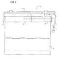
- the blind is a roll screen 10 which comprises a set frame 12 fixed to a fixed surface such as a window frame or the like, a pair of supporting plates 14 fitted to respective side ends of the set frame 12, a rolling-up pipe 16 which is a rotation shaft turnably supported to the pair of supporting plates 14, a screen 18 which is a shielding member, and a control section 20 disposed between one end of the rolling-up pipe 16 and one of the supporting plates 14.
- One end of the screen 18 is connected to the rolling-up pipe 16, and which is hung from the rolling-up pipe 16 so as to be wound around or unwound from the rolling-up pipe 16.
- the one end of the rolling-up pipe 16 is supported by a supporting shaft 22 extending from the one of the supporting plates 14 into the inside of the rolling-up pipe 16.
- the supporting shaft 22 is basically fixed relative to the supporting plates 14, however can be turnable relative to the supporting plates 14 only when it is concurrently used for adjusting a lower limit mechanism (not shown).
- a lower limit mechanism (not shown).
- the supporting shaft 22 is supposed to be a basically stationary fixed member within the range of the normal use of the blind 10.
- the control section 20 and the rolling-up pipe 16 are linked to each other via a first clutch mechanism 24, and the rolling-up pipe 16 and the supporting shaft 22 are linked via a second clutch mechanism 26.
- a brake 28 for decelerating the turning of the rolling-up pipe 16 is disposed within the rolling-up pipe 16.
- the control section 20 includes a control case 30 fixed to the one of the supporting plate 14 with fastenings (not shown), a fixed shaft 32 fixed to the one of the supporting plates 14, a pulley 34 supported to be turnable around the fixed shaft 32, a control member 36 of which one end is attached to the pulley 34 to permit the control member 36 to be wound around and unwound from the pulley 34, and a spiral spring 38 as an urging member, of which one end is fixed to the fixed shaft 32 and the other end is fixed to the pulley 34.
- the length of the fixed shaft 32 in its axial direction is short enough to allow the pulley 34 to support thereon, and the supporting shaft 22 coaxially penetrates the fixed shaft 32 .
- the fixed shaft 32 and the supporting shaft 22 cannot turn relative to each other.
- control member 36 comprises a rolling-up cord 40 which is directly wound around the pulley 34, a holding cord 42 whose upper end is tied with the lower end of the rolling-up cord 40, an operating knob 43 attached to the lower end of the holding cord 42, and a stopper 44.
- the stopper 44 is provided with an accommodating portion 44a thereinside for accommodating a knot formed between the lower end of the rolling-up cord 40 and the upper end of the holding cord 42 so that the stopper 44 is greater in diameter than the cords 40 and 42.
- the cords 40 and 42 may be shaped like either thin strings or thin tapes.
- the control member 36 passes through an opening 30a formed in a lower part of the control case 30 and moves in and out of the control case 30, but the stopper 44 cannot pass the opening 30a and comes into contact with the control case 30 around the opening 30a. Therefore, part of the holding cord 42 is always hanging down below the control case 30, thereby preventing the control member 36 from being excessively wound around the pulley 34 and from rising out of the user's reach. Accordingly the suspending length of the holding cord 42 when it is not operated is appropriate not only for the ease of handling by the user but also for keeping the aesthetic appearance of the blind satisfactory and preventing it from catching a passer-by, a pet animal, furniture or the like.
- a plurality of engaging stubs 34a are formed on an end side surface of the pulley 34, facing toward the rolling-up pipe 16.
- the engaging stubs 34a are separated from one another in the circumferential direction along a certain circular contour.
- engaging stubs 34a engage with engaging stubs 48a similarly formed on a rotator 48.
- the engaging stubs 48a are also formed separate from one another in the circumferential direction along a certain circular contour as shown in FIG. 5.
- the position of the rotator 48 in the axial direction relative to the supporting shaft 22 is restricted by a washer 49 so that, when the engaging stubs 48a of the rotator 48 engage with the engaging stubs 34a of the pulley 34, slight clearances are formed between the two sets of engaging stubs in both the circumferential and axial directions.
- the above-described first clutch mechanism 24 comprises this input shaft 50, a switch-over guide 52 as a switch-over member, engaging pieces 54, and an output shaft 56.
- the switch-over guide 52 is on the outer circumference side of the input shaft 50 and can turn relative to the input shaft 50 within a prescribed turning range.
- the engaging pieces 54 turn together with the switch-over guide 52 and are guided by the switch-over guide 52 to be movable in the radial direction.
- the output shaft 56 is arranged outside the switch-over guide 52 and coupled to one end of the rolling-up pipe 16.
- the turning of the pulley 34 in one direction is transmitted to the rolling-up pipe 16, but the turning of the pulley 34 in the other direction is not transmitted to the rolling-up pipe 16. Nor is the turning of the rolling-up pipe 16 transmitted to the pulley 34.
- the detailed configuration will be described below.
- a plurality of (three) concave grooves 50a and a plurality of (three) ribs 50b protruding in the radial direction are alternately formed in/on the circumferential surface of the input shaft 50 so as to be separated at equal intervals in the circumferential direction.
- a plurality (three) of recessed grooves 52a and a plurality (three) of recessed long grooves 52b are formed in the switch-over guide 52, respectively separated at equal intervals in the circumferential direction, to correspond to the concave grooves 50a and the ribs 50b.
- the ribs 50b are inserted into the recessed long grooves 52b with clearances in the circumferential direction.
- the switch-over guide 52 is turnably supported at a radially enlarged part of the supporting shaft 22.
- the inner sectional contour of the switch-over guide 52 to be contacted with the supporting shaft 22 preferably has a non circular shape, e.g. has flat surfaces 52c which are separated at equal intervals in the circumferential direction and somewhat protrude toward the supporting shaft 22 as shown in FIG. 8 and FIG. 9.
- the columnar-shaped engaging piece 54 is inserted into each of the recessed grooves 52a of the switch-over guide 52.
- a plurality (nine) of concave grooves 56a are formed in the inner circumferential surface of the output shaft 56.
- the engaging pieces 54 which are movable in the radial direction in the recessed grooves 52a, can be switched over according to a relative angular movement between the switch-over guide 52 and the input shaft 50 between a state in which they are moved inwardly in the concave grooves 50a of the input shaft 50 and another state in which they are moved outwardly into the concave grooves 56a in the output shaft 56.
- a clutch case 60 extending into the inside of the rolling-up pipe 16 is integrally provided on the output shaft 56.
- the above-described second clutch mechanism 26 comprises this clutch case 60, a slider 62 turning together with the clutch case 60, a clutch drum 64 which restricts the movements of the slider 62, and a clutch spring 66 which allows the clutch drum 64 to turn only in one direction.
- concave grooves 60a extending in the axial direction are formed in an inner surface of the clutch case 60, and part of the slider 62 is inserted into one of the concave grooves 60a to be movable in the axial direction.
- the clutch drum 64 is formed with a guide groove 64a. The rest part of the slider 62 is inserted into the guide groove 64a which guides the movement of the slider 62.
- the guide groove 64a has one endless groove portion 64b and two branch groove portions 64c branching out of the endless groove portion 64b.
- An engaging portion 64e and a stop portion 64d are formed within each of the branch groove portions 64c.
- the clutch spring 66 is wound around the supporting shaft 22, and one end of it is connected to the clutch drum 64.
- the rotation of the clutch case 60 integrated with the output shaft 56 causes the slider 62 to start from the stop portion 64d of the clutch drum 64 and to move to the endless groove portion 64b.
- the pulley 34 is rotated by the spiral spring 38 in the direction of winding the rolling-up cord 40.
- This rotation of the pulley 34 is transmitted to the input shaft 50 via the rotator 48.
- the rotation of the input shaft 50 relative to the switch-over guide 52 causes the engaging pieces 54 to move into the concave grooves 50a in the input shaft 50, and the linkage between the input shaft 50 and the output shaft 56 is undone (FIG. 12 (c)).
- the output shaft 56 is relieved of linkage to both the pulley 34 and the supporting shaft 22 by the first clutch mechanism 24 and the second clutch mechanism 26.
- the pulley 34 is turned by the spiral spring 38 in the direction of winding the rolling-up cord 40, the rolling-up pipe 16 is turned by the own weight of the screen 18 in the direction of unwinding the screen, and the pulley 34 and the rolling-up pipe 16 are turned independently of each other, though in the same direction.
- the pulley 34 winds the rolling-up cord 40 as much as possible, i.e. until the stopper 44 comes into contact with the control case 30.
- the pulley 34 then stops, but the output shaft 56 and the rolling-up pipe 16 continue to turn. In this way, the screen 18 descends by its own weight under deceleration by the brake 28, and stops when it reaches its lower limit (FIG. 12 (d)).
- the switch-over guide 52 since the switch-over guide 52 is held by the flat surfaces 52c relative to the supporting shaft 22 with a force stronger than the turning force of the output shaft 56 but weaker than the urging force of the spiral spring 38, the switch-over guide 52 does not turn following the output shaft 56 while the pulley 34 is not turning but the output shaft 56 is turning.
- the user can keep pulling the holding cord 42 of the control member 36 (FIG. 13A (a)). Then, the rolling-up cord 40 of the control member 36 is unwound from the pulley 34 to be pulled out of the control case 30, and the pulley 34 turns in the unwinding direction.
- the rotation of the clutch case 60 integrated with the output shaft 56 causes the slider 62 to enter into one of the branch groove portions 64c from the endless groove portion 64b of the clutch drum 64, and moves to the engaging portion 64e.
- the slider 62 so acts as to turn the clutch drum 64 in a direction matching the raising direction of the screen, and the loosening of the clutch spring 66 allows the clutch drum 64 to turn in the raising direction.
- the rolling-up cord 40 of the control member 36 Since the rolling-up cord 40 of the control member 36 is limited in length, it cannot be pulled out after it has been pulled to the maximum. When the control member 36 is then released, the spiral spring 38 causes the rolling-up cord 40 to be wound by the pulley 34 (FIG. 13A (b)). Thus, while the pulley 34 rotates in the direction of winding the rolling-up cord 40, this rotation of the pulley 34 is transmitted to the input shaft 50 via the rotator 48, and the resultant rotation of the input shaft 50 relative to the switch-over guide 52 causes the engaging pieces 54 to move inwardly into the concave grooves 50a of the input shaft 50, resulting in unlinking of the input shaft 50 and the output shaft 56 from each other.
- the rotation of the pulley 34 in the direction of winding the rolling-up cord 40 is not transmitted to the output shaft 56.
- the own weight of the screen 18 causes the slider 62 to move from the engaging portion 64e to the stop portion 64d to link the rolling-up pipe 16 and the supporting shaft 22 with each other to stop the screen.
- the first method is to utilize the second clutch mechanism 26 to link the rolling-up pipe 16 and the supporting shaft 22 together.
- the second method is to utilize the first clutch mechanism 24 to link the rolling-up pipe 16 and the pulley 34 together.
- the control member 36 When the screen 18 is to be stopped by the first method, the control member 36 is drawn out in a long stroke. This causes the slider 62 which is moving in the endless groove portion 64b of the clutch drum 64 and rounding along the endless groove portions 64b with turning of the output shaft 56, to move from the endless groove portion 64b into one of the branch groove portion 64c and then reach the engaging portion 64e. When the control member 36 is released, the slider 62 moves from the engaging portion 64e to the stop portion 64d and therefore the rolling-up pipe 16 and the screen 18 stop.
- the control member 36 is drawn out in a short stroke (Fig. 14 (a) ⁇ FIG. 14 (b)) .
- This causes the rotation of the pulley 34 to be transmitted to the input shaft 50, the switch-over guide 52 turns and the engaging pieces 54 move outward to engage with the concave grooves 56a of the output shaft 56.
- the pulley 34 and the turning output shaft 56 are linked with each other.
- the pulley 34 begins to turn in the reverse direction, namely in the direction of winding the rolling-up cord 40.
- the pulley 34 rotates with being linked with the rolling-up pipe 16.
- the stopper 44 of the control member 36 comes into contact with the control case 30 to make it impossible for the pulley 34 to turn in the direction of winding the rolling-up cord 40, the rolling-up pipe 16 is also made unable to turn.
- the rolling-up pipe 16 and the screen 18 stop.
- the two stop portions 64d are formed in the circumferential direction on the clutch drum 64 in the second clutch mechanism 26, whereas the nine concave grooves 56a of the output shaft 56 are formed in the circumferential direction in the first clutch mechanism 24.
- the first clutch mechanism 24 can link the pulley 34 and the rolling-up pipe 16 with each other and stop them in a smaller turning angle, and accordingly the second method serves to shorten the rising height of the screen 18 from the time the control member 36 is operated until the screen 18 actually stops, making it possible to stop the screen 18 more quickly and at a desired height.
- the control member 36 in this embodiment is drawn out of the pulley 34 only when it is to be operated as described above. It is immediately wound up by the spiral spring 38 upon completion of each round of operation, the control member 36 does not hang long, and can be prevented from catching a passer-by, a pet animal or furniture.
- pulley 34 and the first clutch mechanism 24 are coupled with each other via the rotator 48 in the above-described embodiment, it is also possible to integrate the pulley 34 and the input shaft 50 with each other without the rotator 48. It is also conceivable to configure the fixed shaft 32 and the supporting shaft 22 integrally.
- the supporting shaft 22 or the like is bent by the weight of the screen 18 to incline the first clutch mechanism 24, it is possible to prevent the inclination and bend from being transmitted to the pulley 34 and the spiral spring 38 urging the pulley 34 from running into faulty operation because the rotator 48 as in this embodiment is disposed to leave slight clearances in the circumferential direction and the axial direction between the engaging stubs 34a of the pulley 34 and the engaging stubs 48a of the rotator 48, and/or because the pulley 34 is supported by the fixed shaft 32 separate from and shorter than the supporting shaft 22.
- FIG. 15 shows an overall front view of a second preferred embodiment of the present invention. It is different from the first embodiment wherein the screen 18 descends by its own weight when the rolling-up pipe 16 is unlinked from the supporting shaft 22 by the second clutch mechanism 26, in that a rolling-up spring 70 is arranged in the rolling-up pipe 16 to urge all the time the rolling-up pipe 16 in the direction of winding the screen.
- This embodiment can be accomplished by vertically inverting the guide groove 64a of the clutch drum 64 in the second clutch mechanism 26 as it is shown in the development view of the first embodiment.
- the screen 18 can be stopped by having the second clutch mechanism 26 link the rolling-up pipe 16 and the supporting shaft 22 with each other.
- the second clutch mechanism 26 unlinks the rolling-up pipe 16 and the supporting shaft 22 from each other in response to the rotation of the pulley 34 by a prescribed angle, the screen 18 is raised by the winding force of the rolling-up spring 70. It is also possible to stop the rising screen 18 by the action of the first clutch mechanism 24 or the second clutch mechanism 26.
- This embodiment also provides similar actions and effects to those of the first embodiment.
- FIG. 16 shows a third preferred embodiment of the present invention.
- This embodiment constitutes an application of the invention to a horizontal blind 80, wherein many slats 82 serving as a shielding member hang from a head box 81 and are aligned vertically and supported by ladder cords 84. Further, lifting cords 88 penetrate the slats 82 and bottom ends of the lifting cords 88 are attached to a bottom rail 86 disposed underneath the slats 82. Upper ends of the ladder cords 84 and of the lifting cords 88 are connected to drums 90 disposed within the head box 81. The ladder cords 84 turn together with the drums 90 within a prescribed range of angles, and outside that range the ladder cords 84 do not turn with the drums 90.
- the lifting cords 88 can be wound around and unwound from the drums 90.
- the drums 90 are mounted on a rotation shaft 92 extending within the head box 81 in the lengthwise direction so as to unturnable relative to the rotation shaft 92.
- the rotation shaft 92 is connected to a follower 94 as a rotation shaft, so as to be unturnable relative to the follower 94.
- the control section 20 having a pulley 34, a control member 36 and a spiral spring 38 is disposed at one end of the head box 81.
- the control section 20 and the follower 94 are linked with each other via the first clutch mechanism 24, while the follower 94 and the supporting shaft 22 are linked with each other via the second clutch mechanism 26.
- the follower 94 here can be integrated with the output shaft 56 of the first clutch mechanism 24 and the clutch case 60 of the second clutch mechanism 26.
- the brake 28 is connected to one end of the rotation shaft 92.
- the configurations of the control section 20, the first clutch mechanism 24 and the second clutch mechanism 26 are the same as their respective counterparts in the first embodiment.
- This embodiment also provides similar effects to those of the first embodiment.
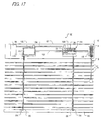
- FIG. 17 shows a fourth embodiment of the present invention.
- the same or similar members as or to those in previous embodiments are denoted by respectively the same reference signs.
- This embodiment is another example of application to a horizontal blind, wherein many slats 82 serving as a shielding member hang from a head box 81 and are aligned vertically and supported by ladder cords 84. Further, lifting cords 88 penetrate the slats 82 and bottom ends of the lifting cords 88 are attached to a bottom rail 86 disposed underneath the slats 82. Upper ends of the ladder cords 84 and of the lifting cords 88 are connected to drums 100 as rotation shafts, disposed within the head box 81. The ladder cords 84 turn together with the drums 100 within a prescribed range of angles, and outside that range the ladder cords 84 do not turn with the drums 100. The upper ends of the lifting cords 88 are so connected to the drums 100 as to permit the lifting cords to be wound up and unwound from the drums 100.
- the first clutch mechanism 24 and the second clutch mechanism 26 are disposed within each of the drums 100.
- Each of the drums 100 here can be integrated with the output shaft 56 of the first clutch mechanism 24 and the clutch case 60 of the second clutch mechanism 26.
- Each of the drums 100 and the second clutch mechanism 26 and the first clutch mechanism 24 are rotatably supported by the supporting shaft 22 fixed to the head box 81.
- the input shaft 50 of the first clutch mechanism 24 is unturnably connected to a rotation shaft 102 extending within the head box 81 in the lengthwise direction, and the rotation shaft 102 is connected to the pulley 34 of the control section 20 via the rotator 48.
- the rotator 48 and the input shaft 50 are separate units and are coupled with each other via the rotation shaft 102.
- Each of the drums 100 meshes with a gear fixed to a common auxiliary shaft 104, and the rotation of each drum 100 is synchronized with that of the auxiliary shaft 104.
- the brake 28 is connected to one end of the auxiliary shaft 104.
- the configurations of the control section 20, the first clutch mechanism 24 and the second clutch mechanism 26 are the same as those of their respective counterparts in the first embodiment or the third embodiment.
- This embodiment also provides similar effects to those of the first embodiment and the third embodiment.
- third and fourth embodiments are examples of application of the present invention to horizontal blinds
- the invention can as well be applied to other desired types of blinds including pleated screens and Roman shades.
Landscapes
- Engineering & Computer Science (AREA)
- Structural Engineering (AREA)
- Architecture (AREA)
- Civil Engineering (AREA)
- Operating, Guiding And Securing Of Roll- Type Closing Members (AREA)
- Blinds (AREA)
- Curtains And Furnishings For Windows Or Doors (AREA)
Applications Claiming Priority (1)
| Application Number | Priority Date | Filing Date | Title |
|---|---|---|---|
| JP2005054364A JP4440802B2 (ja) | 2005-02-28 | 2005-02-28 | ブラインド |
Publications (3)
| Publication Number | Publication Date |
|---|---|
| EP1707735A2 true EP1707735A2 (de) | 2006-10-04 |
| EP1707735A3 EP1707735A3 (de) | 2014-06-11 |
| EP1707735B1 EP1707735B1 (de) | 2018-05-02 |
Family
ID=36579457
Family Applications (1)
| Application Number | Title | Priority Date | Filing Date |
|---|---|---|---|
| EP06251036.7A Expired - Lifetime EP1707735B1 (de) | 2005-02-28 | 2006-02-27 | Rollo |
Country Status (7)
| Country | Link |
|---|---|
| US (1) | US7665507B2 (de) |
| EP (1) | EP1707735B1 (de) |
| JP (1) | JP4440802B2 (de) |
| KR (1) | KR101182509B1 (de) |
| CN (1) | CN1828005B (de) |
| AU (1) | AU2006200861B2 (de) |
| CA (1) | CA2537380C (de) |
Cited By (1)
| Publication number | Priority date | Publication date | Assignee | Title |
|---|---|---|---|---|
| CN104274053A (zh) * | 2013-07-05 | 2015-01-14 | 德侑股份有限公司 | 窗帘、其操控系统及操作方法 |
Families Citing this family (48)
| Publication number | Priority date | Publication date | Assignee | Title |
|---|---|---|---|---|
| US7578334B2 (en) * | 2005-06-03 | 2009-08-25 | Hunter Douglas Inc. | Control system for architectural coverings with reversible drive and single operating element |
| WO2009052693A1 (fr) * | 2007-10-24 | 2009-04-30 | Zhu, Xiaoying | Dispositif d'écran à enroulement |
| US20090120592A1 (en) * | 2007-11-14 | 2009-05-14 | Hunter Douglas Inc. | Control unit for lift system for coverings for architectural openings |
| JP5107698B2 (ja) * | 2007-12-27 | 2012-12-26 | 株式会社ニチベイ | ロールスクリーン |
| US20090283226A1 (en) * | 2008-05-16 | 2009-11-19 | Li-Ming Cheng | Roller Shade |
| KR100875633B1 (ko) * | 2008-06-16 | 2008-12-26 | 곽재석 | 원 코드 블라인드 |
| JP5315009B2 (ja) * | 2008-11-05 | 2013-10-16 | 株式会社ニチベイ | ブラインド |
| GB2469097A (en) * | 2009-04-01 | 2010-10-06 | Euan Eric Neil Thomas George Davidson | Rewinding mechanism and container for bag with rewinding mechanism for the bag |
| JP5361676B2 (ja) * | 2009-11-18 | 2013-12-04 | トーソー株式会社 | カムクラッチ装置及びこれを用いた間仕切り装置及び二重スクリーン日射遮蔽装置 |
| JP5680923B2 (ja) * | 2010-01-25 | 2015-03-04 | トーソー株式会社 | 日射遮蔽装置 |
| KR101213737B1 (ko) * | 2010-07-14 | 2012-12-18 | 김정민 | 안전 끈을 갖는 롤 블라인드 |
| US8356653B2 (en) * | 2010-08-25 | 2013-01-22 | Teh Yor Co., Ltd. | Control module having a clutch for raising and lowering a window shade |
| JP5666965B2 (ja) * | 2011-04-08 | 2015-02-12 | トーソー株式会社 | 日射遮蔽装置 |
| US8517081B2 (en) * | 2011-08-11 | 2013-08-27 | K.E. & Kingstone Co., Ltd. | Transmission assembly for a roller blind |
| KR101301798B1 (ko) * | 2011-08-19 | 2013-09-10 | 김정민 | 단일 안전코드를 갖는 롤 블라인드 |
| WO2013027878A1 (ko) * | 2011-08-25 | 2013-02-28 | Kim Jung-Min | 단일 안전코드를 갖는 롤 블라인드 |
| BR112014007960A2 (pt) * | 2011-10-03 | 2017-04-11 | Hunter Douglas | métodos e aparelho para controle de montagem de cobertura para abertura arquitetônica |
| KR101289584B1 (ko) * | 2011-11-22 | 2013-07-24 | 김정민 | 무소음 양방향 클러치를 갖는 롤 블라인드 |
| US9765864B2 (en) | 2012-02-23 | 2017-09-19 | Teh Yor Co., Ltd. | Window shade and its control module |
| TWI604124B (zh) * | 2012-02-23 | 2017-11-01 | 德侑股份有限公司 | 窗簾及其控制模組 |
| CN103284572B (zh) * | 2012-02-23 | 2016-01-20 | 德侑股份有限公司 | 窗帘及其控制模组 |
| CN102767329B (zh) * | 2012-07-23 | 2014-07-16 | 李七妹 | 一种窗帘用单拉绳驱动装置 |
| US8844605B2 (en) * | 2012-09-12 | 2014-09-30 | Philip Ng | Single cord operated clutch for roller blind |
| AU2013381892B2 (en) * | 2013-03-15 | 2018-02-22 | Hunter Douglas Inc. | Position lock for roller supported architectural coverings |
| KR101422999B1 (ko) * | 2013-05-02 | 2014-07-28 | 김정민 | 어린이 안전사고 예방을 위한 자유낙하식 슬림형 롤 블라인드 |
| KR101359513B1 (ko) * | 2013-08-27 | 2014-02-07 | 곽재석 | 이중원단 블라인드의 원단 각도 조절장치 |
| JP6184883B2 (ja) * | 2014-01-30 | 2017-08-23 | 株式会社ニチベイ | ブラインド用クラッチ装置 |
| JP6219739B2 (ja) * | 2014-02-05 | 2017-10-25 | 株式会社ニチベイ | ブラインド用操作装置 |
| US9657517B2 (en) * | 2014-06-09 | 2017-05-23 | Teh Yor Co., Ltd. | Window shade and actuating system thereof |
| JP6386321B2 (ja) * | 2014-09-26 | 2018-09-05 | 株式会社Tok | クラッチ装置、及び、それを用いた日射遮蔽装置 |
| US9341020B1 (en) * | 2015-03-24 | 2016-05-17 | Uni-Soleil Ent. Co., Ltd. | Single pull-cord controller of roman shade |
| US20160281423A1 (en) * | 2015-03-24 | 2016-09-29 | Uni-Soleil Ent. Co. Ltd. | Single-cord control device for roller blind |
| CA2921529C (en) | 2015-05-01 | 2023-03-07 | Zmc Metal Coating Inc. | Bi-directional clutch with return feature |
| CN105525857B (zh) * | 2016-02-04 | 2017-05-10 | 王海锋 | 窗帘控制器 |
| JP6810524B2 (ja) * | 2016-02-19 | 2021-01-06 | 立川ブラインド工業株式会社 | クラッチ装置及び遮蔽装置 |
| JP7123526B2 (ja) * | 2017-03-30 | 2022-08-23 | 立川ブラインド工業株式会社 | ロールスクリーン |
| JP7037427B2 (ja) * | 2018-04-26 | 2022-03-16 | 株式会社ニチベイ | ブラインドの操作装置、ブラインド |
| KR102071941B1 (ko) * | 2018-04-27 | 2020-01-31 | (주)한솔아이엠비 | 구동 줄이 한 줄로 형성되는 블라인드용 구동장치 |
| JP7197327B2 (ja) * | 2018-11-02 | 2022-12-27 | 株式会社ニチベイ | 縦型ブラインド |
| TWI701009B (zh) * | 2019-09-20 | 2020-08-11 | 程田有限公司 | 窗簾控制器 |
| NL2024607B1 (en) * | 2020-01-06 | 2021-09-07 | Vako B V | Operating mechanism for a cordless window covering |
| WO2021146170A1 (en) * | 2020-01-16 | 2021-07-22 | Teh Yor Co., Ltd. | Window shade and actuating system thereof |
| AU2021232880B2 (en) * | 2020-03-09 | 2024-04-04 | Teh Yor Co., Ltd. | Window shade and actuating system thereof |
| US12503913B2 (en) | 2021-01-28 | 2025-12-23 | Syncproto Co., Ltd. | Blind lifting device and a blind lifting control module thereof |
| TWI739711B (zh) * | 2021-01-28 | 2021-09-11 | 型態同步科技股份有限公司 | 升降控制模組及捲簾升降裝置 |
| WO2023049567A1 (en) * | 2021-09-22 | 2023-03-30 | Teh Yor Co., Ltd. | Window shade and actuating system thereof |
| KR102492330B1 (ko) * | 2022-06-03 | 2023-01-26 | 김상익 | 한 가닥의 당김줄로 작동되는 롤 블라인드용 구동장치 |
| CA3232918A1 (en) * | 2023-04-03 | 2025-06-23 | Rollease Acmeda, Inc. | Wand for a cord driven blind assembly |
Family Cites Families (27)
| Publication number | Priority date | Publication date | Assignee | Title |
|---|---|---|---|---|
| US1797204A (en) * | 1927-08-31 | 1931-03-17 | Donaldson Mfg Company Ltd | Roller blind and fitting therefor |
| US2012261A (en) * | 1934-04-04 | 1935-08-27 | John B Drumm | Roller for shades, awnings, curtains or the like |
| US4476910A (en) * | 1981-02-10 | 1984-10-16 | Kabushiki Kaisha Nichibei | Roll-blind |
| US4492261A (en) * | 1981-09-28 | 1985-01-08 | General Drapery Services, Inc. | Shading system |
| US4466475A (en) * | 1981-11-16 | 1984-08-21 | Kabushiki Kaisha Nichibei | Device for driving and stopping a roll blind |
| US4662423A (en) * | 1982-10-31 | 1987-05-05 | Kabushiki Kaisha Nichibei | Device for operating roll-screen |
| JPS59195985A (ja) | 1983-04-20 | 1984-11-07 | 株式会社ニチベイ | シ−ト巻上げ巻降し装置 |
| IT208635Z2 (it) * | 1986-12-17 | 1988-05-28 | Mottura Spa | Tenda a rullo con freno a masse centrifughe disposto all esterno del rullo e sopporto d estremita includente tale freno |
| US5099906A (en) * | 1989-09-19 | 1992-03-31 | Metaco Co., Ltd. | Roller screen unit |
| JPH03228992A (ja) | 1990-01-31 | 1991-10-09 | Solar Fective Prod Ltd | ローラーブラインド装置 |
| JP2656147B2 (ja) * | 1990-10-13 | 1997-09-24 | 立川ブラインド工業株式会社 | ロールブラインドのスクリーン昇降装置 |
| JPH06212867A (ja) | 1992-11-30 | 1994-08-02 | Toso Co Ltd | コード操作可能なロールブラインド |
| US5566741A (en) * | 1993-06-02 | 1996-10-22 | Kabushiki Kaisha Nichibei | Roll screen apparatus |
| JP2803983B2 (ja) | 1993-09-17 | 1998-09-24 | 株式会社ニチベイ | ブラインド |
| US5890529A (en) * | 1997-01-29 | 1999-04-06 | Kirsch Inc. | Dual action retractable cord take-up reel |
| US5791393A (en) * | 1997-03-31 | 1998-08-11 | Judkins; Ren | Shade operator |
| US5927370A (en) * | 1997-11-18 | 1999-07-27 | Judkins; Ren | Release brake shade operator |
| US6129131A (en) * | 1997-11-26 | 2000-10-10 | Hunter Douglas Inc. | Control system for coverings for architectural openings |
| JP3273007B2 (ja) | 1997-12-25 | 2002-04-08 | 立川ブラインド工業株式会社 | たくし上げカーテン |
| CA2277603C (en) * | 1998-07-15 | 2007-01-09 | Konrad Welfonder | A winding and unwinding mechanism for blinds and or shades |
| US6131642A (en) * | 1998-09-28 | 2000-10-17 | Hunter Douglas International N.V. | Locking device |
| JP3570926B2 (ja) | 1999-07-13 | 2004-09-29 | 立川ブラインド工業株式会社 | ロールブラインドの昇降装置 |
| US6142211A (en) * | 1999-08-10 | 2000-11-07 | Judkins; Ren | Shade operator with release brake |
| US6164428A (en) * | 1999-08-23 | 2000-12-26 | Joel Berman Associates, Inc. | Wrap spring shade operator |
| JP3077194U (ja) * | 2000-10-24 | 2001-05-11 | 株式会社シネマ工房 | 映写スクリーン等のシート巻取装置 |
| JP3795741B2 (ja) | 2000-10-30 | 2006-07-12 | 株式会社ニチベイ | 外部日除け装置 |
| US7128126B2 (en) * | 2003-03-04 | 2006-10-31 | Hunter Douglas Inc. | Control system for architectural coverings with reversible drive and single operating element |
-
2005
- 2005-02-28 JP JP2005054364A patent/JP4440802B2/ja not_active Expired - Fee Related
-
2006
- 2006-02-16 US US11/355,416 patent/US7665507B2/en active Active
- 2006-02-21 CA CA2537380A patent/CA2537380C/en not_active Expired - Lifetime
- 2006-02-23 KR KR1020060017909A patent/KR101182509B1/ko not_active Expired - Lifetime
- 2006-02-27 EP EP06251036.7A patent/EP1707735B1/de not_active Expired - Lifetime
- 2006-02-28 AU AU2006200861A patent/AU2006200861B2/en not_active Ceased
- 2006-02-28 CN CN2006100580661A patent/CN1828005B/zh not_active Expired - Fee Related
Cited By (2)
| Publication number | Priority date | Publication date | Assignee | Title |
|---|---|---|---|---|
| CN104274053A (zh) * | 2013-07-05 | 2015-01-14 | 德侑股份有限公司 | 窗帘、其操控系统及操作方法 |
| US9284774B2 (en) | 2013-07-05 | 2016-03-15 | Teh Yor Co., Ltd. | Window shade and actuating system and operating method thereof |
Also Published As
| Publication number | Publication date |
|---|---|
| JP2006241692A (ja) | 2006-09-14 |
| AU2006200861B2 (en) | 2011-04-14 |
| CN1828005A (zh) | 2006-09-06 |
| JP4440802B2 (ja) | 2010-03-24 |
| US20060191650A1 (en) | 2006-08-31 |
| KR101182509B1 (ko) | 2012-09-12 |
| EP1707735B1 (de) | 2018-05-02 |
| US7665507B2 (en) | 2010-02-23 |
| KR20060095472A (ko) | 2006-08-31 |
| AU2006200861A1 (en) | 2006-09-14 |
| CA2537380C (en) | 2013-03-05 |
| CA2537380A1 (en) | 2006-08-28 |
| CN1828005B (zh) | 2012-09-05 |
| EP1707735A3 (de) | 2014-06-11 |
Similar Documents
| Publication | Publication Date | Title |
|---|---|---|
| EP1707735B1 (de) | Rollo | |
| US8720523B2 (en) | Shielding apparatus and clutch used for the same | |
| KR20170105568A (ko) | 윈도우 쉐이드 및 그 제어 시스템 | |
| JP2000145328A (ja) | 日射遮蔽装置の遮蔽材昇降装置及び横型ブラインドのスラット駆動装置 | |
| JP4704772B2 (ja) | ブラインド | |
| JP2000220369A (ja) | ブラインド装置 | |
| JP2015028297A (ja) | 遮蔽装置 | |
| EP3902969B1 (de) | Betätigungsmechanismus für eine fensterabdeckung und fensterabdeckung | |
| JP2014031715A (ja) | 遮蔽装置 | |
| KR101176323B1 (ko) | 단일 조작코드를 갖는 롤 블라인드 | |
| JP5315009B2 (ja) | ブラインド | |
| JP2017082585A (ja) | 遮蔽装置 | |
| JP4696030B2 (ja) | 窓用調光部材昇降装置 | |
| JP2012011055A (ja) | ブラインド | |
| JP5421069B2 (ja) | 遮蔽装置 | |
| JP4431810B2 (ja) | ブラインド装置 | |
| JP7274371B2 (ja) | 動力伝達装置および遮蔽装置 | |
| JP7611083B2 (ja) | 日射遮蔽装置用の操作装置及び日射遮蔽装置 | |
| CN1910334B (zh) | 日射遮蔽材料升降装置 | |
| US20250263979A1 (en) | Reciprocating type pull rod driving apparatus and curtain system including same | |
| WO2005056967A1 (ja) | 日射遮蔽材昇降装置 | |
| HK1168403B (en) | Shielding device and clutch used therefor |
Legal Events
| Date | Code | Title | Description |
|---|---|---|---|
| PUAI | Public reference made under article 153(3) epc to a published international application that has entered the european phase |
Free format text: ORIGINAL CODE: 0009012 |
|
| AK | Designated contracting states |
Kind code of ref document: A2 Designated state(s): AT BE BG CH CY CZ DE DK EE ES FI FR GB GR HU IE IS IT LI LT LU LV MC NL PL PT RO SE SI SK TR |
|
| AX | Request for extension of the european patent |
Extension state: AL BA HR MK YU |
|
| PUAL | Search report despatched |
Free format text: ORIGINAL CODE: 0009013 |
|
| AK | Designated contracting states |
Kind code of ref document: A3 Designated state(s): AT BE BG CH CY CZ DE DK EE ES FI FR GB GR HU IE IS IT LI LT LU LV MC NL PL PT RO SE SI SK TR |
|
| AX | Request for extension of the european patent |
Extension state: AL BA HR MK YU |
|
| RIC1 | Information provided on ipc code assigned before grant |
Ipc: E06B 9/90 20060101ALN20140502BHEP Ipc: E06B 9/42 20060101AFI20140502BHEP Ipc: E06B 9/78 20060101ALI20140502BHEP |
|
| 17P | Request for examination filed |
Effective date: 20141202 |
|
| RBV | Designated contracting states (corrected) |
Designated state(s): AT BE BG CH CY CZ DE DK EE ES FI FR GB GR HU IE IS IT LI LT LU LV MC NL PL PT RO SE SI SK TR |
|
| RBV | Designated contracting states (corrected) |
Designated state(s): AT BE BG CH CY CZ DE DK EE ES FI FR GB GR HU IE IS IT LI LT LU LV MC NL PL PT RO SE SI SK TR |
|
| AKX | Designation fees paid |
Designated state(s): AT BE BG CH CY CZ DE DK EE ES FI FR GB GR HU IE IS IT LI LT LU LV MC NL PL PT RO SE SI SK TR |
|
| AXX | Extension fees paid |
Extension state: HR Extension state: BA Extension state: YU Extension state: MK Extension state: AL |
|
| STAA | Information on the status of an ep patent application or granted ep patent |
Free format text: STATUS: EXAMINATION IS IN PROGRESS |
|
| 17Q | First examination report despatched |
Effective date: 20170728 |
|
| GRAP | Despatch of communication of intention to grant a patent |
Free format text: ORIGINAL CODE: EPIDOSNIGR1 |
|
| STAA | Information on the status of an ep patent application or granted ep patent |
Free format text: STATUS: GRANT OF PATENT IS INTENDED |
|
| RIC1 | Information provided on ipc code assigned before grant |
Ipc: E06B 9/78 20060101ALI20170927BHEP Ipc: E06B 9/90 20060101ALN20170927BHEP Ipc: E06B 9/42 20060101AFI20170927BHEP |
|
| RIC1 | Information provided on ipc code assigned before grant |
Ipc: E06B 9/78 20060101ALI20171018BHEP Ipc: E06B 9/90 20060101ALN20171018BHEP Ipc: E06B 9/42 20060101AFI20171018BHEP |
|
| INTG | Intention to grant announced |
Effective date: 20171031 |
|
| RIC1 | Information provided on ipc code assigned before grant |
Ipc: E06B 9/90 20060101ALN20171220BHEP Ipc: E06B 9/42 20060101AFI20171220BHEP Ipc: E06B 9/78 20060101ALI20171220BHEP |
|
| GRAJ | Information related to disapproval of communication of intention to grant by the applicant or resumption of examination proceedings by the epo deleted |
Free format text: ORIGINAL CODE: EPIDOSDIGR1 |
|
| GRAP | Despatch of communication of intention to grant a patent |
Free format text: ORIGINAL CODE: EPIDOSNIGR1 |
|
| RIC1 | Information provided on ipc code assigned before grant |
Ipc: E06B 9/42 20060101AFI20180105BHEP Ipc: E06B 9/90 20060101ALN20180105BHEP Ipc: E06B 9/78 20060101ALI20180105BHEP |
|
| RIC1 | Information provided on ipc code assigned before grant |
Ipc: E06B 9/90 20060101ALN20180123BHEP Ipc: E06B 9/78 20060101ALI20180123BHEP Ipc: E06B 9/42 20060101AFI20180123BHEP |
|
| INTG | Intention to grant announced |
Effective date: 20180207 |
|
| GRAS | Grant fee paid |
Free format text: ORIGINAL CODE: EPIDOSNIGR3 |
|
| GRAA | (expected) grant |
Free format text: ORIGINAL CODE: 0009210 |
|
| STAA | Information on the status of an ep patent application or granted ep patent |
Free format text: STATUS: THE PATENT HAS BEEN GRANTED |
|
| AK | Designated contracting states |
Kind code of ref document: B1 Designated state(s): AT BE BG CH CY CZ DE DK EE ES FI FR GB GR HU IE IS IT LI LT LU LV MC NL PL PT RO SE SI SK TR |
|
| REG | Reference to a national code |
Ref country code: GB Ref legal event code: FG4D |
|
| REG | Reference to a national code |
Ref country code: CH Ref legal event code: EP Ref country code: AT Ref legal event code: REF Ref document number: 995440 Country of ref document: AT Kind code of ref document: T Effective date: 20180515 |
|
| REG | Reference to a national code |
Ref country code: DE Ref legal event code: R096 Ref document number: 602006055290 Country of ref document: DE |
|
| REG | Reference to a national code |
Ref country code: IE Ref legal event code: FG4D |
|
| REG | Reference to a national code |
Ref country code: CH Ref legal event code: NV Representative=s name: ISLER AND PEDRAZZINI AG, CH |
|
| REG | Reference to a national code |
Ref country code: NL Ref legal event code: FP |
|
| REG | Reference to a national code |
Ref country code: LT Ref legal event code: MG4D |
|
| PG25 | Lapsed in a contracting state [announced via postgrant information from national office to epo] |
Ref country code: ES Free format text: LAPSE BECAUSE OF FAILURE TO SUBMIT A TRANSLATION OF THE DESCRIPTION OR TO PAY THE FEE WITHIN THE PRESCRIBED TIME-LIMIT Effective date: 20180502 Ref country code: LT Free format text: LAPSE BECAUSE OF FAILURE TO SUBMIT A TRANSLATION OF THE DESCRIPTION OR TO PAY THE FEE WITHIN THE PRESCRIBED TIME-LIMIT Effective date: 20180502 Ref country code: SE Free format text: LAPSE BECAUSE OF FAILURE TO SUBMIT A TRANSLATION OF THE DESCRIPTION OR TO PAY THE FEE WITHIN THE PRESCRIBED TIME-LIMIT Effective date: 20180502 Ref country code: FI Free format text: LAPSE BECAUSE OF FAILURE TO SUBMIT A TRANSLATION OF THE DESCRIPTION OR TO PAY THE FEE WITHIN THE PRESCRIBED TIME-LIMIT Effective date: 20180502 Ref country code: BG Free format text: LAPSE BECAUSE OF FAILURE TO SUBMIT A TRANSLATION OF THE DESCRIPTION OR TO PAY THE FEE WITHIN THE PRESCRIBED TIME-LIMIT Effective date: 20180802 |
|
| PG25 | Lapsed in a contracting state [announced via postgrant information from national office to epo] |
Ref country code: LV Free format text: LAPSE BECAUSE OF FAILURE TO SUBMIT A TRANSLATION OF THE DESCRIPTION OR TO PAY THE FEE WITHIN THE PRESCRIBED TIME-LIMIT Effective date: 20180502 Ref country code: GR Free format text: LAPSE BECAUSE OF FAILURE TO SUBMIT A TRANSLATION OF THE DESCRIPTION OR TO PAY THE FEE WITHIN THE PRESCRIBED TIME-LIMIT Effective date: 20180803 |
|
| REG | Reference to a national code |
Ref country code: AT Ref legal event code: MK05 Ref document number: 995440 Country of ref document: AT Kind code of ref document: T Effective date: 20180502 |
|
| PG25 | Lapsed in a contracting state [announced via postgrant information from national office to epo] |
Ref country code: PT Free format text: LAPSE BECAUSE OF FAILURE TO SUBMIT A TRANSLATION OF THE DESCRIPTION OR TO PAY THE FEE WITHIN THE PRESCRIBED TIME-LIMIT Effective date: 20180903 |
|
| PG25 | Lapsed in a contracting state [announced via postgrant information from national office to epo] |
Ref country code: EE Free format text: LAPSE BECAUSE OF FAILURE TO SUBMIT A TRANSLATION OF THE DESCRIPTION OR TO PAY THE FEE WITHIN THE PRESCRIBED TIME-LIMIT Effective date: 20180502 Ref country code: PL Free format text: LAPSE BECAUSE OF FAILURE TO SUBMIT A TRANSLATION OF THE DESCRIPTION OR TO PAY THE FEE WITHIN THE PRESCRIBED TIME-LIMIT Effective date: 20180502 Ref country code: DK Free format text: LAPSE BECAUSE OF FAILURE TO SUBMIT A TRANSLATION OF THE DESCRIPTION OR TO PAY THE FEE WITHIN THE PRESCRIBED TIME-LIMIT Effective date: 20180502 Ref country code: SK Free format text: LAPSE BECAUSE OF FAILURE TO SUBMIT A TRANSLATION OF THE DESCRIPTION OR TO PAY THE FEE WITHIN THE PRESCRIBED TIME-LIMIT Effective date: 20180502 Ref country code: AT Free format text: LAPSE BECAUSE OF FAILURE TO SUBMIT A TRANSLATION OF THE DESCRIPTION OR TO PAY THE FEE WITHIN THE PRESCRIBED TIME-LIMIT Effective date: 20180502 Ref country code: CZ Free format text: LAPSE BECAUSE OF FAILURE TO SUBMIT A TRANSLATION OF THE DESCRIPTION OR TO PAY THE FEE WITHIN THE PRESCRIBED TIME-LIMIT Effective date: 20180502 Ref country code: RO Free format text: LAPSE BECAUSE OF FAILURE TO SUBMIT A TRANSLATION OF THE DESCRIPTION OR TO PAY THE FEE WITHIN THE PRESCRIBED TIME-LIMIT Effective date: 20180502 |
|
| REG | Reference to a national code |
Ref country code: DE Ref legal event code: R097 Ref document number: 602006055290 Country of ref document: DE |
|
| PLBE | No opposition filed within time limit |
Free format text: ORIGINAL CODE: 0009261 |
|
| STAA | Information on the status of an ep patent application or granted ep patent |
Free format text: STATUS: NO OPPOSITION FILED WITHIN TIME LIMIT |
|
| 26N | No opposition filed |
Effective date: 20190205 |
|
| PG25 | Lapsed in a contracting state [announced via postgrant information from national office to epo] |
Ref country code: SI Free format text: LAPSE BECAUSE OF FAILURE TO SUBMIT A TRANSLATION OF THE DESCRIPTION OR TO PAY THE FEE WITHIN THE PRESCRIBED TIME-LIMIT Effective date: 20180502 |
|
| PG25 | Lapsed in a contracting state [announced via postgrant information from national office to epo] |
Ref country code: LU Free format text: LAPSE BECAUSE OF NON-PAYMENT OF DUE FEES Effective date: 20190227 Ref country code: MC Free format text: LAPSE BECAUSE OF FAILURE TO SUBMIT A TRANSLATION OF THE DESCRIPTION OR TO PAY THE FEE WITHIN THE PRESCRIBED TIME-LIMIT Effective date: 20180502 |
|
| REG | Reference to a national code |
Ref country code: BE Ref legal event code: MM Effective date: 20190228 |
|
| REG | Reference to a national code |
Ref country code: IE Ref legal event code: MM4A |
|
| PG25 | Lapsed in a contracting state [announced via postgrant information from national office to epo] |
Ref country code: IE Free format text: LAPSE BECAUSE OF NON-PAYMENT OF DUE FEES Effective date: 20190227 |
|
| PG25 | Lapsed in a contracting state [announced via postgrant information from national office to epo] |
Ref country code: BE Free format text: LAPSE BECAUSE OF NON-PAYMENT OF DUE FEES Effective date: 20190228 Ref country code: FR Free format text: LAPSE BECAUSE OF NON-PAYMENT OF DUE FEES Effective date: 20190228 |
|
| PG25 | Lapsed in a contracting state [announced via postgrant information from national office to epo] |
Ref country code: TR Free format text: LAPSE BECAUSE OF FAILURE TO SUBMIT A TRANSLATION OF THE DESCRIPTION OR TO PAY THE FEE WITHIN THE PRESCRIBED TIME-LIMIT Effective date: 20180502 |
|
| PG25 | Lapsed in a contracting state [announced via postgrant information from national office to epo] |
Ref country code: CY Free format text: LAPSE BECAUSE OF FAILURE TO SUBMIT A TRANSLATION OF THE DESCRIPTION OR TO PAY THE FEE WITHIN THE PRESCRIBED TIME-LIMIT Effective date: 20180502 |
|
| PG25 | Lapsed in a contracting state [announced via postgrant information from national office to epo] |
Ref country code: IS Free format text: LAPSE BECAUSE OF FAILURE TO SUBMIT A TRANSLATION OF THE DESCRIPTION OR TO PAY THE FEE WITHIN THE PRESCRIBED TIME-LIMIT Effective date: 20180902 |
|
| PG25 | Lapsed in a contracting state [announced via postgrant information from national office to epo] |
Ref country code: HU Free format text: LAPSE BECAUSE OF FAILURE TO SUBMIT A TRANSLATION OF THE DESCRIPTION OR TO PAY THE FEE WITHIN THE PRESCRIBED TIME-LIMIT; INVALID AB INITIO Effective date: 20060227 |
|
| PGFP | Annual fee paid to national office [announced via postgrant information from national office to epo] |
Ref country code: NL Payment date: 20240129 Year of fee payment: 19 |
|
| PGFP | Annual fee paid to national office [announced via postgrant information from national office to epo] |
Ref country code: DE Payment date: 20240116 Year of fee payment: 19 Ref country code: CH Payment date: 20240301 Year of fee payment: 19 Ref country code: GB Payment date: 20240118 Year of fee payment: 19 |
|
| PGFP | Annual fee paid to national office [announced via postgrant information from national office to epo] |
Ref country code: IT Payment date: 20240126 Year of fee payment: 19 |
|
| REG | Reference to a national code |
Ref country code: DE Ref legal event code: R119 Ref document number: 602006055290 Country of ref document: DE |
|
| REG | Reference to a national code |
Ref country code: CH Ref legal event code: PL |
|
| REG | Reference to a national code |
Ref country code: NL Ref legal event code: MM Effective date: 20250301 |
|
| PG25 | Lapsed in a contracting state [announced via postgrant information from national office to epo] |
Ref country code: CH Free format text: LAPSE BECAUSE OF NON-PAYMENT OF DUE FEES Effective date: 20250228 |
|
| GBPC | Gb: european patent ceased through non-payment of renewal fee |
Effective date: 20250227 |
|
| PG25 | Lapsed in a contracting state [announced via postgrant information from national office to epo] |
Ref country code: NL Free format text: LAPSE BECAUSE OF NON-PAYMENT OF DUE FEES Effective date: 20250301 |
|
| PG25 | Lapsed in a contracting state [announced via postgrant information from national office to epo] |
Ref country code: DE Free format text: LAPSE BECAUSE OF NON-PAYMENT OF DUE FEES Effective date: 20250902 |
|
| PG25 | Lapsed in a contracting state [announced via postgrant information from national office to epo] |
Ref country code: GB Free format text: LAPSE BECAUSE OF NON-PAYMENT OF DUE FEES Effective date: 20250227 |
|
| PG25 | Lapsed in a contracting state [announced via postgrant information from national office to epo] |
Ref country code: IT Free format text: LAPSE BECAUSE OF NON-PAYMENT OF DUE FEES Effective date: 20250227 |