EP1707751A2 - Außendichtungsanordnung für eine Turbinenschaufel - Google Patents
Außendichtungsanordnung für eine Turbinenschaufel Download PDFInfo
- Publication number
- EP1707751A2 EP1707751A2 EP06250465A EP06250465A EP1707751A2 EP 1707751 A2 EP1707751 A2 EP 1707751A2 EP 06250465 A EP06250465 A EP 06250465A EP 06250465 A EP06250465 A EP 06250465A EP 1707751 A2 EP1707751 A2 EP 1707751A2
- Authority
- EP
- European Patent Office
- Prior art keywords
- ring
- lugs
- seats
- split
- diameter
- Prior art date
- Legal status (The legal status is an assumption and is not a legal conclusion. Google has not performed a legal analysis and makes no representation as to the accuracy of the status listed.)
- Granted
Links
Images


Classifications
-
- F—MECHANICAL ENGINEERING; LIGHTING; HEATING; WEAPONS; BLASTING
- F01—MACHINES OR ENGINES IN GENERAL; ENGINE PLANTS IN GENERAL; STEAM ENGINES
- F01D—NON-POSITIVE DISPLACEMENT MACHINES OR ENGINES, e.g. STEAM TURBINES
- F01D11/00—Preventing or minimising internal leakage of working-fluid, e.g. between stages
- F01D11/08—Preventing or minimising internal leakage of working-fluid, e.g. between stages for sealing space between rotor blade tips and stator
-
- F—MECHANICAL ENGINEERING; LIGHTING; HEATING; WEAPONS; BLASTING
- F01—MACHINES OR ENGINES IN GENERAL; ENGINE PLANTS IN GENERAL; STEAM ENGINES
- F01D—NON-POSITIVE DISPLACEMENT MACHINES OR ENGINES, e.g. STEAM TURBINES
- F01D25/00—Component parts, details, or accessories, not provided for in, or of interest apart from, other groups
- F01D25/24—Casings; Casing parts, e.g. diaphragms, casing fastenings
- F01D25/246—Fastening of diaphragms or stator-rings
-
- F—MECHANICAL ENGINEERING; LIGHTING; HEATING; WEAPONS; BLASTING
- F01—MACHINES OR ENGINES IN GENERAL; ENGINE PLANTS IN GENERAL; STEAM ENGINES
- F01D—NON-POSITIVE DISPLACEMENT MACHINES OR ENGINES, e.g. STEAM TURBINES
- F01D9/00—Stators
- F01D9/02—Nozzles; Nozzle boxes; Stator blades; Guide conduits, e.g. individual nozzles
- F01D9/04—Nozzles; Nozzle boxes; Stator blades; Guide conduits, e.g. individual nozzles forming ring or sector
-
- Y—GENERAL TAGGING OF NEW TECHNOLOGICAL DEVELOPMENTS; GENERAL TAGGING OF CROSS-SECTIONAL TECHNOLOGIES SPANNING OVER SEVERAL SECTIONS OF THE IPC; TECHNICAL SUBJECTS COVERED BY FORMER USPC CROSS-REFERENCE ART COLLECTIONS [XRACs] AND DIGESTS
- Y02—TECHNOLOGIES OR APPLICATIONS FOR MITIGATION OR ADAPTATION AGAINST CLIMATE CHANGE
- Y02T—CLIMATE CHANGE MITIGATION TECHNOLOGIES RELATED TO TRANSPORTATION
- Y02T50/00—Aeronautics or air transport
- Y02T50/60—Efficient propulsion technologies, e.g. for aircraft
Definitions
- This invention relates to a method and apparatus for retaining the outer air seal of a turbine rotor blade stage in assembly.
- this invention pertains to an improved means for retaining the outer air seal of a jet engine turbine rotor stage in assembly.
- this type of retainer has been relatively difficult and time consuming when engine maintenance was required, thus extending the aircraft down time.
- the air seal retention systems that are in present day use are relatively heavy and costly devices requiring the use of special tools to install or remove from the engine.
- a further object of the present invention is to reduce the number of premature failures in jet engine turbine air seal retention systems.
- a still further object of the present invention is to reduce the amount of time needed to install and remove a turbine stage outer air seal retainer of a jet engine.
- Another object of the present invention is to reduce the weight and the cost of a turbine stage outer seal retainer.
- Another object of the present invention is to provide for a more rapid aircraft turn around time during periods of engine maintenance.
- Yet another object of the present invention is to provide a turbine outer air seal retainer that can be installed or removed without the need of special tools.
- a split ring retainer that prevents axial displacement of an annular series of locking key segments which serve to hold the outer air seal assembly of a jet engine turbine rotor stage in locking engagement with the turbine casing.
- the body of the split ring is slidably contained within a radially disposed groove in the turbine casing and has a series of circumferentially spaced raised lugs located around the inside surface of the ring body.
- the inner surfaces of the lugs approximate a circle having a first diameter and are adapted to seat upon axially extended ribs located upon each of the key segments.
- the ribs have seats for receiving the lugs thereon.
- the seats approximate a circle having a second diameter that is greater than the diameter described by the inner surfaces of the ribs so that the split ring is flexed outwardly when the lugs are seated upon the ribs.
- the ring engages each of the key segments to prevent axial movement of the segments and thus retain the segments in a locking position with the outer air seal assembly.
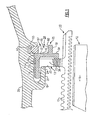
- FIG. 1 there is illustrated a partial side elevation in section in Fig. 1 showing an annular outer air seal assembly 10 of a turbine rotor stage 12.
- the seal assembly contains a circular hook-shaped hanger 13 for locating the air seal 15 around the top edges of the blades 16 of the rotor stage.
- the hanger contains an annular flange 17 that is received within an axially disposed annular groove 19 formed in the turbine casing 20.
- the air seal is connected to the annular flange 17 by means of a radially disposed arm 22.
- One side wall 23 of the arm bears against a radially disposed surface 24 located on the casing to register the air seal in assembly.
- a locking mechanism, generally referenced 25, serves to secure the air seal in a locked and registered position as illustrated in Fig. 1.
- the locking mechanism includes a plurality of arcuate-shaped key segments 28. Each key segment includes a radially disposed arcuate-shaped panel 32 having one or more axially extended arms 33. The arms are arranged to pass through openings provided in the air seal hanger into the axial groove 19 contained in the turbine casing 20.
- a first bearing pad 37 is located upon the outer tip of each arm which rests upon the outer wall of the axially disposed groove 19.
- a second bearing pad 38 is carried upon the lower inner edge of each panel segment and is arranged to rest against the radial arm of the hangar when the key is in a locking position as illustrated in Fig. 1.
- a third bearing pad 40 is located upon the upper surface of the key arm at the corner formed by the arm and the arcuate-shaped panel of each locking key. Bearing pad 40 rests against the inner wall 41 of the axially disposed groove 19 when the key is in a locking position. As can be seen, the bearing pads permit the key segments to move axially into the locking position, however, the pads prevent the key segments from rotating in assembly or moving radially once the key is set in the locking position.
- a split ring retainer is arranged to prevent the key segments from moving axially out of groove 19 once the key segments are placed in the locking position thus retaining the air seal assembly in the desired operative position around the turbine rotor stage 12.
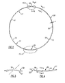
- the split retaining ring 50 is generally circular in form.
- the ring includes a body section 53 having a given thickness (t).
- the ring contains a split section 55 that is cut at an angle (Fig. 10) that allows the ring to be flexed outwardly when a sufficient outwardly directed force is applied to the ring.
- the ring is fabricated of a high strength metal having a resiliency such the ring wants to return to its initial unload condition once the flexing force is released. Many types of spring steel are available that provide both this type of high-strength and resiliency.
- a series of lugs 57-57 are integrally located upon the inner surface 58 of the ring body.
- the lugs are circumferentially spaced about the ring body so that each lug on the ring can be seated upon one of a plurality of rib-like seats 59 that extend outwardly from each of the key segments.
- the outer surfaces 60 on the ribs generally approximate a circle having a first diameter.
- the inner surfaces 61 of the lugs 57 generally approximate a second circle having a second diameter that is less than the first diameter approximated by the lugs when the ring is in an unloaded condition. Accordingly, the ring must be forced outwardly in order to seat the lugs upon the seats of the key segments as best illustrated in Figs. 8-11.
- the body section of the ring is slidably contained within a radially disposed annular groove 63 formed in the turbine casing 20 and surrounds the seats on the key segments so that the ring can move radially in assembly as the lugs are mounted upon the seats.
- An inclined ramp 65 is located on either side of each lug.
- Groove 63 is aligned with each of the locking segments such that side wall 68 of the ring is in contact with the outer wall 70 of each locking segment when the segments are in the locked position.
- the expanded ring is now unable to move radially out of the groove 63 in the casing, and correspondingly, the key segments are unable to move axially out of the locking position.
- the seats on the key segments insure that the split ring will always be loaded radially in an outward direction to prevent the ring from moving inwardly.
- the ramp feature also allows the ring to be installed or removed in either a clockwise or a counterclockwise direction without the need of special tools.
- a detent mechanism generally referenced 80 (Fig. 8) is furnished to prevent improper installation of the ring.
- the detent mechanism as illustrated in Fig. 8, includes a raised platform located on the inside of the ring that is diametrically opposed from the split in the ring.
- a circumferentially extended recess 82 is located in the top surface of the platform and is dimensioned to snuggly receive therein a keeper 83 which is located on one of the key segments.
- a seat as described in detail above may serve as the detent keeper.
- the detent platform again is furnished with an inclined ramp 84 on either side of seat which facilitates the guiding of the keeper into the recess 82 as the ring is rotated within groove 19.
- the ramps again allow the ring to be rotated in either direction during installation and removal and serve to minimize galling and wear on the detent mechanisms.
- the detent mechanism provides a positive tangential locking capability to the ring which resists thermal movement of the ring that might produce an unbalanced load resulting in the ring being fractured and requiring its replacement.
- a section of the ring body 86 located on either side of the detent mechanism has a reduced thickness which allows the ring to adjust its position upon seats positioned on either side of the detent. This in turn facilitates proper positioning of the seats upon the lugs and allows for closure control over the ring's flexibility.
Landscapes
- Engineering & Computer Science (AREA)
- Mechanical Engineering (AREA)
- General Engineering & Computer Science (AREA)
- Turbine Rotor Nozzle Sealing (AREA)
Applications Claiming Priority (1)
| Application Number | Priority Date | Filing Date | Title |
|---|---|---|---|
| US11/091,204 US7334980B2 (en) | 2005-03-28 | 2005-03-28 | Split ring retainer for turbine outer air seal |
Publications (3)
| Publication Number | Publication Date |
|---|---|
| EP1707751A2 true EP1707751A2 (de) | 2006-10-04 |
| EP1707751A3 EP1707751A3 (de) | 2010-05-05 |
| EP1707751B1 EP1707751B1 (de) | 2015-11-04 |
Family
ID=36069083
Family Applications (1)
| Application Number | Title | Priority Date | Filing Date |
|---|---|---|---|
| EP06250465.9A Expired - Lifetime EP1707751B1 (de) | 2005-03-28 | 2006-01-27 | Spaltring zur Befestigung einer Außendichtung einer Turbine |
Country Status (3)
| Country | Link |
|---|---|
| US (1) | US7334980B2 (de) |
| EP (1) | EP1707751B1 (de) |
| JP (1) | JP2006275045A (de) |
Cited By (4)
| Publication number | Priority date | Publication date | Assignee | Title |
|---|---|---|---|---|
| WO2015130538A1 (en) * | 2014-02-25 | 2015-09-03 | Siemens Energy, Inc. | Turbine abradable layer with asymmetric ridges or grooves |
| EP3054115A1 (de) * | 2015-02-06 | 2016-08-10 | United Technologies Corporation | Verfahren zur begrenzung der bewegung eines halterings und halteringanordnung |
| EP3088689A1 (de) * | 2015-04-27 | 2016-11-02 | United Technologies Corporation | Aussendichtungsfederklemmen einer turbinenschaufel |
| CN109072705A (zh) * | 2015-12-18 | 2018-12-21 | 赛峰飞机发动机公司 | 在冷态下弹性保持的涡轮环组件 |
Families Citing this family (38)
| Publication number | Priority date | Publication date | Assignee | Title |
|---|---|---|---|---|
| US7721433B2 (en) * | 2005-03-28 | 2010-05-25 | United Technologies Corporation | Blade outer seal assembly |
| DE102007031711A1 (de) * | 2007-07-06 | 2009-01-08 | Rolls-Royce Deutschland Ltd & Co Kg | Gehäusedeckbandsegment-Aufhängung |
| US8650885B2 (en) * | 2009-12-22 | 2014-02-18 | United Technologies Corporation | Retaining member for use with gas turbine engine shaft and method of assembly |
| US8491267B2 (en) * | 2010-08-27 | 2013-07-23 | Pratt & Whitney Canada Corp. | Retaining ring arrangement for a rotary assembly |
| US8932002B2 (en) | 2010-12-03 | 2015-01-13 | Hamilton Sundstrand Corporation | Air turbine starter |
| US8475122B1 (en) * | 2011-01-17 | 2013-07-02 | Florida Turbine Technologies, Inc. | Blade outer air seal with circumferential cooled teeth |
| US8834106B2 (en) * | 2011-06-01 | 2014-09-16 | United Technologies Corporation | Seal assembly for gas turbine engine |
| WO2013163581A1 (en) * | 2012-04-27 | 2013-10-31 | General Electric Company | System and method of limiting axial movement between a hanger and a fairing assembly in a turbine assembly |
| US8959743B2 (en) | 2012-06-01 | 2015-02-24 | United Technologies Corporation | Retaining ring removal tool |
| US10240467B2 (en) * | 2012-08-03 | 2019-03-26 | United Technologies Corporation | Anti-rotation lug for a gas turbine engine stator assembly |
| FR2995340B1 (fr) * | 2012-09-12 | 2026-03-06 | Snecma | Tole de protection thermique avec butee radiale, notamment pour distributeur de turbomachine |
| CN104981616B (zh) * | 2012-12-13 | 2017-09-26 | 马克卡车公司 | 保持环固持系统和方法 |
| EP3060777B1 (de) * | 2013-10-21 | 2018-12-19 | United Technologies Corporation | Fananordnung für ein gasturbinentriebwerk, zugehöriges herstellungsverfahren und gasturbinentriebwerk |
| DE102013223133B3 (de) * | 2013-11-13 | 2014-10-30 | Intellectual Property Management MTU Aero Engines AG | Gasturbine |
| US10030542B2 (en) * | 2015-10-02 | 2018-07-24 | Honeywell International Inc. | Compliant coupling systems and methods for shrouds |
| US10450882B2 (en) * | 2016-03-22 | 2019-10-22 | United Technologies Corporation | Anti-rotation shim seal |
| DE102018210601A1 (de) * | 2018-06-28 | 2020-01-02 | MTU Aero Engines AG | Segmentring zur montage in einer strömungsmaschine |
| US11480071B2 (en) * | 2020-06-02 | 2022-10-25 | Pratt & Whitney Canada Corp. | Balancing ring geometry |
| CN112594068B (zh) * | 2021-01-21 | 2021-05-28 | 中国航发上海商用航空发动机制造有限责任公司 | 航空发动机的盘鼓密封机构和航空发动机 |
| US11542819B2 (en) * | 2021-02-17 | 2023-01-03 | Pratt & Whitney Canada Corp. | Split ring seal for gas turbine engine rotor |
| US11821320B2 (en) | 2021-06-04 | 2023-11-21 | General Electric Company | Turbine engine with a rotor seal assembly |
| US12270304B2 (en) | 2021-07-26 | 2025-04-08 | General Electric Company | Turbine engine with a floating seal assembly |
| US12000289B2 (en) | 2022-03-10 | 2024-06-04 | General Electric Company | Seal assemblies for turbine engines and related methods |
| US11939888B2 (en) * | 2022-06-17 | 2024-03-26 | Rtx Corporation | Airfoil anti-rotation ring and assembly |
| US12123306B2 (en) | 2022-06-28 | 2024-10-22 | General Electric Company | Seal assemblies for turbine engines and related methods |
| US12123305B2 (en) * | 2022-11-23 | 2024-10-22 | Pratt & Whitney Canada Corp. | Split piston ring seal for a rotating assembly and method of sealing |
| US12006829B1 (en) | 2023-02-16 | 2024-06-11 | General Electric Company | Seal member support system for a gas turbine engine |
| US12486779B2 (en) | 2023-03-08 | 2025-12-02 | General Electric Company | Seal support assembly for a turbine engine |
| US12416243B2 (en) | 2023-03-24 | 2025-09-16 | General Electric Company | Seal support assembly for a turbine engine |
| US12241375B2 (en) | 2023-03-24 | 2025-03-04 | General Electric Company | Seal support assembly for a turbine engine |
| US12372002B2 (en) | 2023-03-24 | 2025-07-29 | General Electric Company | Seal support assembly for a turbine engine |
| US12116896B1 (en) | 2023-03-24 | 2024-10-15 | General Electric Company | Seal support assembly for a turbine engine |
| US12595745B2 (en) | 2023-03-24 | 2026-04-07 | General Electric Company | Seal support assembly for a turbine engine |
| US12215587B2 (en) | 2023-03-24 | 2025-02-04 | General Electric Company | Seal support assembly for a turbine engine |
| US12421861B2 (en) | 2023-03-24 | 2025-09-23 | General Electric Company | Seal support assembly for a turbine engine |
| US12215588B2 (en) | 2023-03-27 | 2025-02-04 | General Electric Company | Seal assembly for a gas turbine engine |
| US12326089B2 (en) | 2023-04-24 | 2025-06-10 | General Electric Company | Seal assembly for a gas turbine engine |
| US12584415B2 (en) | 2024-05-03 | 2026-03-24 | General Electric Company | Turbine engine seal for turbine engines |
Citations (1)
| Publication number | Priority date | Publication date | Assignee | Title |
|---|---|---|---|---|
| EP1079076A2 (de) | 1999-08-25 | 2001-02-28 | General Electric Company | Turbinengehäusekonfiguration mit einer Rückhaltevorrichtung für einen Spannring |
Family Cites Families (4)
| Publication number | Priority date | Publication date | Assignee | Title |
|---|---|---|---|---|
| US4349318A (en) * | 1980-01-04 | 1982-09-14 | Avco Corporation | Boltless blade retainer for a turbine wheel |
| US4307993A (en) * | 1980-02-25 | 1981-12-29 | Avco Corporation | Air-cooled cylinder with piston ring labyrinth |
| FR2694046B1 (fr) * | 1992-07-22 | 1994-09-23 | Snecma | Dispositif d'étanchéité et de rétention pour un rotor entaillé de brochages recevant des pieds d'aubes. |
| US5971703A (en) * | 1997-12-05 | 1999-10-26 | Pratt & Whitney Canada Inc. | Seal assembly for a gas turbine engine |
-
2005
- 2005-03-28 US US11/091,204 patent/US7334980B2/en active Active
-
2006
- 2006-01-27 JP JP2006018437A patent/JP2006275045A/ja active Pending
- 2006-01-27 EP EP06250465.9A patent/EP1707751B1/de not_active Expired - Lifetime
Patent Citations (1)
| Publication number | Priority date | Publication date | Assignee | Title |
|---|---|---|---|---|
| EP1079076A2 (de) | 1999-08-25 | 2001-02-28 | General Electric Company | Turbinengehäusekonfiguration mit einer Rückhaltevorrichtung für einen Spannring |
Cited By (8)
| Publication number | Priority date | Publication date | Assignee | Title |
|---|---|---|---|---|
| WO2015130538A1 (en) * | 2014-02-25 | 2015-09-03 | Siemens Energy, Inc. | Turbine abradable layer with asymmetric ridges or grooves |
| EP3054115A1 (de) * | 2015-02-06 | 2016-08-10 | United Technologies Corporation | Verfahren zur begrenzung der bewegung eines halterings und halteringanordnung |
| US10215099B2 (en) | 2015-02-06 | 2019-02-26 | United Technologies Corporation | System and method for limiting movement of a retainer ring of a gas turbine engine |
| US10975773B2 (en) | 2015-02-06 | 2021-04-13 | Raytheon Technologies Corporation | System and method for limiting movement of a retaining ring |
| EP3088689A1 (de) * | 2015-04-27 | 2016-11-02 | United Technologies Corporation | Aussendichtungsfederklemmen einer turbinenschaufel |
| US9822668B2 (en) | 2015-04-27 | 2017-11-21 | United Technologies Corporation | Blade outer air seal spring clips |
| CN109072705A (zh) * | 2015-12-18 | 2018-12-21 | 赛峰飞机发动机公司 | 在冷态下弹性保持的涡轮环组件 |
| CN109072705B (zh) * | 2015-12-18 | 2021-02-09 | 赛峰飞机发动机公司 | 在冷态下弹性保持的涡轮环组件 |
Also Published As
| Publication number | Publication date |
|---|---|
| JP2006275045A (ja) | 2006-10-12 |
| US20060216143A1 (en) | 2006-09-28 |
| EP1707751B1 (de) | 2015-11-04 |
| EP1707751A3 (de) | 2010-05-05 |
| US7334980B2 (en) | 2008-02-26 |
Similar Documents
| Publication | Publication Date | Title |
|---|---|---|
| EP1707751B1 (de) | Spaltring zur Befestigung einer Außendichtung einer Turbine | |
| US8894371B2 (en) | Rotor section for a rotor of a turbomachine, and rotor blade for a turbomachine | |
| US20030123986A1 (en) | Device for immobilizing blades in a slot of a disk | |
| EP1357254B1 (de) | Befestigungssystem für einen axialbeschaufelten Rotor und Bauteile dazu | |
| US4304523A (en) | Means and method for securing a member to a structure | |
| US7520718B2 (en) | Seal and locking plate for turbine rotor assembly between turbine blade and turbine vane | |
| US7153098B2 (en) | Attachment for a bladed rotor | |
| EP1507067B1 (de) | Vorrichtung zum Verhindern der Drehbewegung des Innendichtungsring in einer Turbomaschine | |
| US6739837B2 (en) | Bladed rotor with a tiered blade to hub interface | |
| US5201799A (en) | Clip attachment for combustor panel | |
| EP2660426B1 (de) | Turbinenanordnung | |
| JP2010156337A (ja) | ロータダブテールのフック−フック嵌合 | |
| US20050123405A1 (en) | Sealing arrangement for an axial turbine wheel | |
| US7165772B1 (en) | Self-locking seal ring | |
| US4630994A (en) | Apparatus for axially and circumferentially locking stationary casing components of turbomachines | |
| US7708529B2 (en) | Rotor of a turbo engine, e.g., a gas turbine rotor | |
| EP0668434B1 (de) | Bauteilfixierungseinrichtung für eine Gasturbine | |
| EP1707749B1 (de) | Außendichtungsanordnung für eine Turbinenschaufel | |
| US6421897B1 (en) | Insertion tool for inserting an O-ring into an internal O-ring | |
| GB2262139A (en) | Fan blade retainer | |
| CN115190947B (zh) | 将带凸缘真空泵安装到真空系统 | |
| EP3519682B1 (de) | Vorrichtung zum halten eines turbinenrades und entsprechendes verfahren | |
| WO2022029406A1 (en) | Seal head assembly and method of assembly of a seal head assembly | |
| WO2016032515A1 (en) | Bayonet arrangement of a casing component using inclined hooks and method for attaching and removing this component |
Legal Events
| Date | Code | Title | Description |
|---|---|---|---|
| PUAI | Public reference made under article 153(3) epc to a published international application that has entered the european phase |
Free format text: ORIGINAL CODE: 0009012 |
|
| AK | Designated contracting states |
Kind code of ref document: A2 Designated state(s): AT BE BG CH CY CZ DE DK EE ES FI FR GB GR HU IE IS IT LI LT LU LV MC NL PL PT RO SE SI SK TR |
|
| AX | Request for extension of the european patent |
Extension state: AL BA HR MK YU |
|
| 17P | Request for examination filed |
Effective date: 20070531 |
|
| PUAL | Search report despatched |
Free format text: ORIGINAL CODE: 0009013 |
|
| AK | Designated contracting states |
Kind code of ref document: A3 Designated state(s): AT BE BG CH CY CZ DE DK EE ES FI FR GB GR HU IE IS IT LI LT LU LV MC NL PL PT RO SE SI SK TR |
|
| AX | Request for extension of the european patent |
Extension state: AL BA HR MK YU |
|
| RIC1 | Information provided on ipc code assigned before grant |
Ipc: F01D 9/04 20060101ALI20100329BHEP Ipc: F01D 25/24 20060101ALI20100329BHEP Ipc: F01D 11/08 20060101AFI20100329BHEP |
|
| 17Q | First examination report despatched |
Effective date: 20101130 |
|
| AKX | Designation fees paid |
Designated state(s): DE FR GB |
|
| GRAP | Despatch of communication of intention to grant a patent |
Free format text: ORIGINAL CODE: EPIDOSNIGR1 |
|
| INTG | Intention to grant announced |
Effective date: 20150515 |
|
| GRAS | Grant fee paid |
Free format text: ORIGINAL CODE: EPIDOSNIGR3 |
|
| GRAA | (expected) grant |
Free format text: ORIGINAL CODE: 0009210 |
|
| AK | Designated contracting states |
Kind code of ref document: B1 Designated state(s): DE FR GB |
|
| REG | Reference to a national code |
Ref country code: GB Ref legal event code: FG4D |
|
| REG | Reference to a national code |
Ref country code: DE Ref legal event code: R081 Ref document number: 602006047133 Country of ref document: DE Owner name: UNITED TECHNOLOGIES CORP. (N.D.GES.D. STAATES , US Free format text: FORMER OWNER: UNITED TECHNOLOGIES CORP. (N.D.GES.D. STAATES DELAWARE), HARTFORD, CONN., US |
|
| REG | Reference to a national code |
Ref country code: DE Ref legal event code: R096 Ref document number: 602006047133 Country of ref document: DE |
|
| REG | Reference to a national code |
Ref country code: FR Ref legal event code: PLFP Year of fee payment: 11 |
|
| REG | Reference to a national code |
Ref country code: DE Ref legal event code: R097 Ref document number: 602006047133 Country of ref document: DE |
|
| PLBE | No opposition filed within time limit |
Free format text: ORIGINAL CODE: 0009261 |
|
| STAA | Information on the status of an ep patent application or granted ep patent |
Free format text: STATUS: NO OPPOSITION FILED WITHIN TIME LIMIT |
|
| 26N | No opposition filed |
Effective date: 20160805 |
|
| REG | Reference to a national code |
Ref country code: FR Ref legal event code: PLFP Year of fee payment: 12 |
|
| REG | Reference to a national code |
Ref country code: FR Ref legal event code: CA Effective date: 20170324 |
|
| REG | Reference to a national code |
Ref country code: DE Ref legal event code: R082 Ref document number: 602006047133 Country of ref document: DE Representative=s name: SCHMITT-NILSON SCHRAUD WAIBEL WOHLFROM PATENTA, DE |
|
| REG | Reference to a national code |
Ref country code: DE Ref legal event code: R082 Ref document number: 602006047133 Country of ref document: DE Representative=s name: SCHMITT-NILSON SCHRAUD WAIBEL WOHLFROM PATENTA, DE Ref country code: DE Ref legal event code: R081 Ref document number: 602006047133 Country of ref document: DE Owner name: UNITED TECHNOLOGIES CORP. (N.D.GES.D. STAATES , US Free format text: FORMER OWNER: UNITED TECHNOLOGIES CORPORATION, HARTFORD, CONN., US |
|
| REG | Reference to a national code |
Ref country code: FR Ref legal event code: PLFP Year of fee payment: 13 |
|
| PGFP | Annual fee paid to national office [announced via postgrant information from national office to epo] |
Ref country code: DE Payment date: 20191218 Year of fee payment: 15 |
|
| REG | Reference to a national code |
Ref country code: DE Ref legal event code: R119 Ref document number: 602006047133 Country of ref document: DE |
|
| PG25 | Lapsed in a contracting state [announced via postgrant information from national office to epo] |
Ref country code: DE Free format text: LAPSE BECAUSE OF NON-PAYMENT OF DUE FEES Effective date: 20210803 |
|
| P01 | Opt-out of the competence of the unified patent court (upc) registered |
Effective date: 20230519 |
|
| PGFP | Annual fee paid to national office [announced via postgrant information from national office to epo] |
Ref country code: GB Payment date: 20241219 Year of fee payment: 20 |
|
| PGFP | Annual fee paid to national office [announced via postgrant information from national office to epo] |
Ref country code: FR Payment date: 20241219 Year of fee payment: 20 |
|
| REG | Reference to a national code |
Ref country code: GB Ref legal event code: PE20 Expiry date: 20260126 |