EP1707757A2 - Dispositif de contrôle du démarrage d'une turbine et méthode correspondante - Google Patents
Dispositif de contrôle du démarrage d'une turbine et méthode correspondante Download PDFInfo
- Publication number
- EP1707757A2 EP1707757A2 EP06005292A EP06005292A EP1707757A2 EP 1707757 A2 EP1707757 A2 EP 1707757A2 EP 06005292 A EP06005292 A EP 06005292A EP 06005292 A EP06005292 A EP 06005292A EP 1707757 A2 EP1707757 A2 EP 1707757A2
- Authority
- EP
- European Patent Office
- Prior art keywords
- turbine
- optimum
- starting
- thermal stress
- manipulated variable
- Prior art date
- Legal status (The legal status is an assumption and is not a legal conclusion. Google has not performed a legal analysis and makes no representation as to the accuracy of the status listed.)
- Granted
Links
Images



Classifications
-
- F—MECHANICAL ENGINEERING; LIGHTING; HEATING; WEAPONS; BLASTING
- F01—MACHINES OR ENGINES IN GENERAL; ENGINE PLANTS IN GENERAL; STEAM ENGINES
- F01D—NON-POSITIVE DISPLACEMENT MACHINES OR ENGINES, e.g. STEAM TURBINES
- F01D19/00—Starting of machines or engines; Regulating, controlling, or safety means in connection therewith
- F01D19/02—Starting of machines or engines; Regulating, controlling, or safety means in connection therewith dependent on temperature of component parts, e.g. of turbine-casing
-
- F—MECHANICAL ENGINEERING; LIGHTING; HEATING; WEAPONS; BLASTING
- F01—MACHINES OR ENGINES IN GENERAL; ENGINE PLANTS IN GENERAL; STEAM ENGINES
- F01D—NON-POSITIVE DISPLACEMENT MACHINES OR ENGINES, e.g. STEAM TURBINES
- F01D17/00—Regulating or controlling by varying flow
-
- F—MECHANICAL ENGINEERING; LIGHTING; HEATING; WEAPONS; BLASTING
- F02—COMBUSTION ENGINES; HOT-GAS OR COMBUSTION-PRODUCT ENGINE PLANTS
- F02C—GAS-TURBINE PLANTS; AIR INTAKES FOR JET-PROPULSION PLANTS; CONTROLLING FUEL SUPPLY IN AIR-BREATHING JET-PROPULSION PLANTS
- F02C9/00—Controlling gas-turbine plants; Controlling fuel supply in air- breathing jet-propulsion plants
- F02C9/16—Control of working fluid flow
- F02C9/20—Control of working fluid flow by throttling; by adjusting vanes
-
- F—MECHANICAL ENGINEERING; LIGHTING; HEATING; WEAPONS; BLASTING
- F05—INDEXING SCHEMES RELATING TO ENGINES OR PUMPS IN VARIOUS SUBCLASSES OF CLASSES F01-F04
- F05D—INDEXING SCHEME FOR ASPECTS RELATING TO NON-POSITIVE-DISPLACEMENT MACHINES OR ENGINES, GAS-TURBINES OR JET-PROPULSION PLANTS
- F05D2260/00—Function
- F05D2260/85—Starting
-
- F—MECHANICAL ENGINEERING; LIGHTING; HEATING; WEAPONS; BLASTING
- F05—INDEXING SCHEMES RELATING TO ENGINES OR PUMPS IN VARIOUS SUBCLASSES OF CLASSES F01-F04
- F05D—INDEXING SCHEME FOR ASPECTS RELATING TO NON-POSITIVE-DISPLACEMENT MACHINES OR ENGINES, GAS-TURBINES OR JET-PROPULSION PLANTS
- F05D2270/00—Control
- F05D2270/01—Purpose of the control system
- F05D2270/11—Purpose of the control system to prolong engine life
- F05D2270/112—Purpose of the control system to prolong engine life by limiting temperatures
-
- F—MECHANICAL ENGINEERING; LIGHTING; HEATING; WEAPONS; BLASTING
- F05—INDEXING SCHEMES RELATING TO ENGINES OR PUMPS IN VARIOUS SUBCLASSES OF CLASSES F01-F04
- F05D—INDEXING SCHEME FOR ASPECTS RELATING TO NON-POSITIVE-DISPLACEMENT MACHINES OR ENGINES, GAS-TURBINES OR JET-PROPULSION PLANTS
- F05D2270/00—Control
- F05D2270/30—Control parameters, e.g. input parameters
- F05D2270/303—Temperature
-
- F—MECHANICAL ENGINEERING; LIGHTING; HEATING; WEAPONS; BLASTING
- F05—INDEXING SCHEMES RELATING TO ENGINES OR PUMPS IN VARIOUS SUBCLASSES OF CLASSES F01-F04
- F05D—INDEXING SCHEME FOR ASPECTS RELATING TO NON-POSITIVE-DISPLACEMENT MACHINES OR ENGINES, GAS-TURBINES OR JET-PROPULSION PLANTS
- F05D2270/00—Control
- F05D2270/40—Type of control system
- F05D2270/44—Type of control system active, predictive, or anticipative
Definitions
- the present invention relates to a turbine starting controller capable of starting a turbine in the shortest time while keeping the thermal stress in a turbine rotor to a prescribed value or less and also relates to a turbine starting control method.
- the surface metal temperature of a turbine rotor rises as the heat transfer rate between the steam and the rotor improves due to a rise in the temperature of inflow steam and an increase in steam flow.
- the temperature of the inner portion of the turbine rotor rises due to the conduction of heat from the rotor surface at a timing delayed from the rise in the surface temperature. A deviation thus occurs in the temperature distribution in the inner portion of the turbine rotor, which will cause thermal stress. Since excessive thermal stress significantly reduces the life of the turbine rotor, the value of the generated thermal stress must be suppressed to an appropriate value or lower.
- Japanese Patent Laid-open (KOKAI) Publication No. HEI 9-317404 describes a device for controlling the starting of a steam turbine so as to minimize the starting time of the steam turbine by limiting the thermal stress on the turbine rotor to a prescribed value or less.
- the turbine starting controller disclosed includes optimum pattern computing means, thermal stress predicting means, pattern correcting means, and manipulated variable adjusting means, forming a cascaded structure in which the calculated value computed by the optimum pattern computing means, the thermal stress predicting means, and the pattern correcting means serves as the set value for the manipulated variable adjusting means.
- the conventional turbine starting controller is endowed with a thermal stress prediction starting control function for feedback-calculating the manipulated variable in the manipulated variable adjusting means so that, with the optimum rotor surface temperature transition pattern calculated on the basis of the predicted thermal stress serving as the set value, the measured value of plant state variables such as the temperature of the turbine rotor matches the set value.
- a drive control is performed on a flow rate adjusting valve by a turbine controller on the basis of the manipulated variable from the manipulated variable adjusting means, thereby controlling the starting of the steam turbine.
- the object of optimization calculation is the plant state variable such as the first stage metal temperature of the turbine rotor or the like, and the manipulated variable adjusting means is provided to calculate the turbine acceleration rate/load increase rate as the final manipulated variable.
- the manipulated variable turbine acceleration rate/load increase rate
- the optimum transition pattern for the plant state variable over a predetermined prediction period from the present to the future is calculated by the optimum pattern computing means, and the computed value (set value) at the current time in the computed optimum transition pattern is used for the determination of the manipulated variable by the manipulated variable adjusting means.
- the optimization calculation in the optimum pattern computing means is a calculation in which the plant state variable in each time step over the prediction period from the current time to the future is taken as a variable, so that if the prediction period consists of m steps, it means that the calculation is to be conducted for an m-variables optimization problem. Calculations involving multivariable optimization result in extremely high computational load (computational complexity), and the high computational complexity makes application to commercialization, that is, application to the actual turbine controllers difficult.
- the present invention was conceived so as to substantially eliminate defects or drawbacks encountered in the prior art mentioned above and an object of the present invention is to provide a turbine starting controller and a starting control method for the turbine starting controller, capable of performing prediction on the thermal stress in the turbine rotor while taking as a variable the turbine acceleration rate/load increase rate that is a directly manipulated variable, and performing optimization calculation on the basis of the predicted thermal stress, thereby achieving improved accuracy of the optimum starting control for the turbine and also allowing a manipulated variable of high accuracy and reliability to be obtained.
- a turbine starting controller for adjusting and controlling an amount of steam or gas flowing into a turbine using a control valve
- the controller including: an optimum starting controlling unit for predicting, while taking as a variable a turbine acceleration rate/load increase rate as a directly manipulated variable, thermal stress generated in a turbine rotor over a prediction period from a current time to a future, calculating for each control period a manipulated variable optimum transition pattern in a prediction period which makes a turbine starting time shortest while keeping the predicted thermal stress equal to or lower than a prescribed value, and determining, as an actual optimum manipulated value, a value at the current time in the manipulated variable optimum transition pattern; and an rpm/load controlling unit to which the optimum manipulated variable from the optimum starting controlling unit is input, for controlling actuation of the control valve.
- the optimum starting controlling unit may include: heat transfer rate predicting means for predicting a heat transfer rate over the prediction period from the present to the future, with a directly manipulated variable of a turbine acceleration rate/load increase rate being taken as a variable; first stage metal temperature predicting means for predicting a rate of change of first stage metal temperature in the prediction period on the basis of the predicted heat transfer rate from the heat transfer rate predicting means and a measured first stage metal temperature at the current time; thermal stress predicting means for predicting the thermal stress generated in the turbine rotor on the basis of the predicted rate of change of first stage metal temperature from the first stage metal temperature predicting means; and optimization calculating means for calculating, for each control period, the manipulated variable optimum transition pattern in the prediction period which makes the turbine starting time shortest while keeping the predicted thermal stress equal to or lower than the prescribed value under a constraint of operating conditions of a power plant, and the optimization calculating means is configured to determine as the actual optimum manipulated variable the value at the current time in
- the optimum starting controlling unit may further include first stage steam temperature predicting means for predicting a first stage steam temperature over the predetermined prediction period from the present to the future.
- the optimum starting controlling unit may form a closed optimization calculation cycle composed of the heat transfer rate predicting means, the first stage metal temperature predicting means, the thermal stress predicting means, and the optimization calculating means, and the optimization calculating means outputs a manipulated variable at the current time in the manipulated variable optimum transition pattern to the rpm/load controlling unit as an optimum turbine acceleration rate/optimum load increase rate.
- optimization calculating means included in the optimum starting controlling unit may be configured to simplify optimization calculation by assuming the turbine acceleration rate/load increase rate in the prediction period to be constant to reduce the number of variables for optimization calculation by the optimization calculating means.
- the optimum starting controlling unit may include heat transfer rate prediction model modifying means for adapting a heat transfer rate prediction model, which is based on the manipulated variable in the thermal stress predicting means, on the basis of a measured plant value for each control period.
- optimum starting control correcting means may be further provided on an output side of the optimum starting controlling unit.
- the optimum starting control correcting means is set to receive an input of plant constraint conditions that are not taken into account by the optimum starting controlling unit under the constraint of power plant operating conditions, and correct the optimum manipulated variable calculated by the optimum starting controlling unit or a plant starting schedule.
- a turbine starting control method for adjusting and controlling an amount of steam or gas flowing into a turbine using a control valve, the method including: a thermal stress predicting step of predicting, with respect to an assumed manipulated variable, a thermal stress generated in a turbine rotor over a prediction period from a current time to a future; and an optimization calculation step of calculating for each predetermined control period a manipulated variable optimum transition pattern while keeping the predicted thermal stress equal to or lower than a prescribed value under a constraint of plant operating conditions.
- a value at the current time in the manipulated variable optimum transition pattern is determined as an actual optimum manipulated variable.
- the turbine starting control method may further include a heat transfer rate predicting step of predicting a heat transfer rate in the prediction period on the basis of the manipulated variable in an optimization process from the optimization calculation step; and a first stage metal temperature predicting step of predicting a first stage metal temperature in the prediction period from the predicted heat transfer rate and a measured first stage metal temperature, and upon receiving the predicted rate of change of the first metal temperature from the first stage metal temperature predicting step, the thermal stress in the turbine rotor is predicted in the thermal stress predicting step, and the optimization calculation step of calculating the manipulated variable optimum transition pattern for each predetermined control period from the predicted thermal stress is repeated, thus forming an optimization calculation cycle.
- optimization calculation may be simplified by assuming the manipulated variable in the prediction period to be constant to reduce the number of variables for the optimization calculation.
- the heat transfer rate predicting step may include a prediction model correcting step of adapting a heat transfer rate model, which is based on the manipulated variable, on the basis of measured plant values for each control period.
- a turbine starting controller for adjusting and controlling an amount of steam or gas flowing into a turbine, including an optimum starting controlling unit having: a thermal stress predicting unit for calculating a predicted thermal stress value in a prediction period with respect to each of manipulated variables at a plurality of points assumed in advance; and an approximate optimization calculating unit for approximately calculating, from a maximum value of the thermal stress predicted by the thermal stress predicting unit, an optimum manipulated variable that makes a turbine starting time shortest while keeping the maximum value of the thermal stress equal to or lower than a prescribed value under a constraint of plant operating conditions, through straightforward deterministic operation.
- a turbine starting control method for a turbine having a control valve for adjusting and controlling an amount of steam or gas flowing into the turbine including: a thermal stress predicting step of calculating a predicted thermal stress value in a prediction period with respect to each of manipulated variables at a plurality of points assumed in advance; and an approximate optimization calculation step of approximately calculating, from a maximum value of the thermal stress, an optimum manipulated variable that makes a turbine starting time shortest while keeping the maximum value of the thermal stress equal to or lower than a prescribed value under a constraint of plant operating conditions, for each control period through straightforward deterministic operation.
- the approximate optimization calculation step includes outputting as an optimum turbine acceleration rate/load increase rate the optimum manipulated variable approximately calculated for each control period.
- the thermal stress generated in the turbine rotor is predicted while taking as a variable the turbine acceleration rate/load increase rate that is a manipulated variable, and the shortest turbine starting time can be realized while keeping the predicted thermal stress equal to or lower than the prescribed value, whereby the accuracy of the optimum starting control for the turbine can be enhanced, and a manipulated variable of high accuracy and reliability can be obtained.
- the turbine starting controller and the starting control method for the turbine starting controller according to the present invention, by means of the optimization calculation assuming a constant turbine acceleration rate/load increase rate in the prediction period, the variables for the optimization calculation can be reduced to simplify the calculation, whereby the optimum manipulated variable can be quickly obtained with relatively little computational complexity.
- the calculation for the predicted thermal stress is carried out with respect to the turbine acceleration rate/load increase rate at each of the plurality of preset points, and on the basis of the results of the calculation, the optimum turbine acceleration rate/load increase rate is obtained through inverse operation using linear interpolation, whereby the turbine acceleration rate/load increase rate as a highly accurate manipulated variable of a quasi-optimum solution can be obtained.
- FIG. 1 is a schematic diagram showing the first embodiment of a turbine starting controller according to the present invention.
- a turbine starting controller 10 is a controller for achieving optimum starting of a steam turbine 11 or a gas turbine.
- optimum starting refers to such a starting control as to achieve the shortest turbine starting while keeping the thermal stress of a turbine rotor equal to or lower than a prescribed value.
- a main steam pipe 12 for guiding main steam from a steam generator such as a boiler, not shown.
- a flow rate adjusting valve 13 as a control value is provided at some midpoint of the main steam pipe 12.
- the flow rate adjusting valve 13 is subjected to a drive control by the turbine starting controller 10, thus effecting control so as to achieve optimum starting of the steam turbine 11.
- the steam turbine 1 is connected to a power generator 15.
- Required electric power is obtained by rotationally driving the power generator 15 through the driving of the steam turbine 11.
- the turbine starting controller 10 performs the control on the revolution (rpm) of the steam turbine 11 and on the load of the power generator 15.
- the turbine starting controller 10 adjusts and controls the control value for adjusting the flow rate of main steam or the flow rate of gas flowing into the steam turbine 11 or the gas turbine, thereby controlling the rpm and load of the steam turbine 11 and the power generator 15, respectively.
- the turbine starting controller 10 has optimum starting controlling means 17 for outputting an optimum turbine acceleration rate/load increase rate calculated from a plant state variable, and rpm/load controlling means 18 for performing rpm/load control by performing valve control on the control valve on the basis of the turbine acceleration rate/load rise rate.
- the optimum starting controlling means 17 obtains, through calculation from plant state variables such as a main steam pressure P ms , a main steam temperature T ms , a turbine rpm ⁇ , and a generator load MW, the optimum turbine acceleration rate/load increase rate for achieving the shortest starting time while keeping the thermal stress generated in the turbine rotor of the steam turbine 11, or the gas turbine, equal to or lower than a prescribed value.
- the optimum turbine acceleration/load increase rate which is the optimum manipulated variable obtained through repetitive calculation is output to the rpm/load controlling means 18 serving as valve drive controlling means.
- the rpm/load controlling means 18 is input with the optimum turbine acceleration rate/load increase rate signal so as to perform drive control on the flow rate adjusting valve 13 as the control valve, thereby performing the control on the turbine rpm and the generator load.
- the turbine acceleration rate refers to the rate of change in the rotor rpm of the turbine rotor
- the load increase rate refers to the rate of change in the load of the generator.
- the first stage steam temperature predicting means 21 of the optimum starting controlling means 17 is input with the measured values of the main steam pressure P ms and of the main steam temperature T ms as the plant state variables for the power plant and is adapted to predict the first stage steam temperature T s (k+j) in the prediction period through calculation.
- the heat transfer rate predicting means 22 is input with the measured values of the turbine rpm ⁇ of the steam turbine 11 and of the generator load MW and predicts the heat transfer rate h f from the first stage steam temperature T s to the first stage metal temperature T met of the turbine rotor based on a turbine acceleration rate pattern ⁇ and a load increase rate pattern ⁇ MW in the optimization process as assumed manipulated variables for the prediction period from the optimization calculating means 25.
- the first stage metal temperature predicting means 23 is input with the first stage metal temperature T met as the measured value and predicts the first stage metal temperature T met (k+j) in the prediction period from the first stage steam temperature T s (k+j) predicted by the first stage steam temperature predicting means 21 and the heat transfer rate h f (k+j) predicted by the heat transfer rate predicting means 22, thereby calculating a predicted rate of change of the first stage metal temperature ⁇ T met .
- the thermal stress predicting means 24 predicts the thermal stress ⁇ s (k+j) in the prediction period generated in the turbine rotor.
- An optimization transition pattern is computed by the optimization calculating means 25 performing repeated optimization calculation for the turbine acceleration rate/load increase rate pattern as the manipulated variable based on the predicted thermal stress ⁇ s (k+j) from the thermal stress predicting means 24.
- the optimization calculating means 25 Based on the optimization transition pattern, the optimization calculating means 25 outputs, to the rpm/load controlling means 18, the values at the current time as the optimum turbine acceleration rate ⁇ ⁇ opt and the optimum load increase rate ⁇ MW opt representing the optimum manipulated variables.
- the rpm/load controlling means 18 functions as valve controlling means for the flow rate adjusting valve 13 serving as the control valve. With the optimum turbine acceleration rate ⁇ opt and the optimum load increase rate ⁇ MW opt as the optimum manipulated variables, the rpm/load controlling means 18 performs drive control on the flow rate adjusting valve 13, that is, valve opening adjusting control, on the basis of the optimum manipulated variables.
- the optimization calculating means 25 feeds back the turbine acceleration rate pattern ⁇ and the load increase rate pattern ⁇ MW in the optimization process to the heat transfer rate predicting means 22.
- the heat transfer rate predicting means 22 predicts the heat transfer rate hf(k+j) in the prediction period, and the first stage metal surface predicting means 23 calculates the predicted rate of change of the first stage metal temperature ⁇ T met (k+j).
- the thermal stress predicting means 24 predicts the thermal stress ⁇ s (k+j) in the prediction period from the predicted rate of change of the first stage metal temperature ⁇ T met (k+j), and the optimization calculating means 25, to which the predicted thermal stress ⁇ s (k+j) is input, repeatedly performs the optimization calculation for obtaining the turbine acceleration rate/load increase rate pattern as the manipulated variable.
- the optimization calculating means 25 optimizes the patterning of the turbine acceleration rate/load increase rate as the manipulated variable based on the above optimization calculation (control) cycle, thereby calculating the optimum transition pattern.
- the optimization calculating means 25 outputs, to the rpm/load controlling means 18, the values at the current time in the optimum transition pattern as the optimized turbine acceleration rate (that is, the optimum turbine acceleration rate ⁇ ⁇ opt ) and the optimized load increase rate (that is, the optimum load increase rate ⁇ MW opt ).
- the cycle of output from the optimization calculating means 25 to the rpm/load controlling means 18 is set as one control period.
- the frequency of the output from the optimization calculating means 25 to the rpm/load controlling means 18 may be every plural optimization control cycles. Normally, one control period, for example, one minute, is an optimum value update period obtained through repetition of plural optimization calculation cycles.
- the predicted first stage steam temperature T s (k+j) is represented as a constant with respect to the turbine acceleration rate ⁇ and the load increase rate ⁇ MW being the manipulated variables as optimization variables. That is, the first stage steam temperature predicting means 21 is placed outside of the optimization calculation cycle and is independent from the turbine acceleration rate ⁇ and the load increase rate ⁇ MW as the manipulated variables, thus functioning as a constant.
- T met ( k ) T met ( k ⁇ 1 ) + h f ( k ) ⁇ ⁇ T s ( k ⁇ 1 ) ⁇ T met ( k ⁇ 1 ) ⁇ where T met (k): first stage metal temperature at current time (k)
- the first stage metal temperature T met (k+j) is calculated using the heat transfer equation represented by the expression (4) based on the predicted first stage steam temperature T s (k+j) from the first stage steam temperature predicting means 21, the predicted heat transfer rate hf(k+j) from the heat transfer rate predicting means 22, and the first stage metal temperature T met (k) at the current time, the first stage metal temperature T met (k+j) can be predicted by the following expression.
- the calculation expression for the rotor surface thermal stress generated in the turbine rotor at the current time k takes into account only the radial heat distribution, under the assumption that the turbine rotor is a cylinder of an infinite length (infinite cylinder).
- the expression for determining the thermal stress in the turbine rotor is expressed by the following state-space model expressions.
- X e (k), ⁇ T met (k), and A e , B e , C e in the expressions (11) and (12) are represented as follows.
- a e [ A B 0 1 ]
- B e [ D 1 ]
- C e ( C 0 ) ⁇
- a thermal stress prediction model for predicting the thermal stress over a period from the current time k to a future time up to M steps advanced from the current time k is represented by the following state-space model expression.
- the expression (15) represents a thermal stress prediction model with the first stage metal temperature change prediction vector [ ⁇ T met ] taken as input.
- the optimization problem of determining the turbine acceleration rate pattern for realizing the shortest starting time while keeping the thermal stress generated in the turbine rotor during the startup of the power plant equal to or lower than a prescribed value is formularized as follows by the optimization calculating means 25.
- Constraint condition Satisfy the following expression with respect to a given prescribed thermal stress value ⁇ max .
- Numerical Expression 17 ( ⁇ s ( k + 1 ) ⁇ s ( k + 2 ) ⁇ s ( k + 3 ) ⁇ ⁇ s ( k + m ) ) ⁇ ( ⁇ max ⁇ max ⁇ max ⁇ ⁇ max )
- the manipulated variable lower limit value ⁇ min is switched over as follows, for example, depending on whether or not the turbine rotor rpm falls within the critical rpm region.
- the turbine acceleration rate is not put on HOLD and can be set to a value equal to or higher than the value ⁇ min without fail.
- the critical rpm region falls within a region of 900 rpm to 3300 rpm.
- the optimization represents an m-variables non-linear optimization problem, which can be solved by the technique of line search such as the quasi-Newton method.
- the leading optimum manipulated variable ⁇ ⁇ (k) is determined as an optimum turbine acceleration rate at the current time k, and the optimum turbine acceleration rate signal ⁇ ⁇ opt is output to the rpm/load controlling means 18.
- the optimization calculating means 25 can formularize and calculate the optimization of the turbine acceleration rate pattern (and the generator load increase rate pattern) in the prediction period.
- the optimization problem of the turbine acceleration rate pattern (and the generator load increase rate pattern) in the prediction period can be significantly simplified from that of m-variables optimization to that of one-variable optimization, which proves advantageous in mounting the turbine starting controller 10 for actual use.
- the turbine starting controller 10 is activated to start the power plant.
- the starting of the power plant is carried out by the optimum starting controlling means 17.
- the first stage steam temperature predicting means 21 Upon the start-up of the optimum starting controlling means 17, the first stage steam temperature predicting means 21 is driven.
- the heat transfer rate predicting means 22 appropriately sets the initial value of the turbine acceleration rate/load increase rate pattern in the prediction period, which is the assumed manipulated variable, predicts the heat transfer rate h f (k+j) in the prediction period from the measured value of the current turbine rpm ⁇ (k)/generator load MW(k), and outputs the predicted heat transfer rate h f (k+j) to the first stage metal temperature predicting means 23.
- the first stage metal temperature predicting means 23 is input with the measured value of the first stage metal temperature T met of the steam turbine 11, and from the predicted first stage steam temperature T s (k+j) and the predicted heat transfer rate h f (k+j), calculates the first stage metal temperature T met (k+j) in the prediction period.
- the predicted first stage metal temperature T met (k+j) calculated by the first stage metal temperature predicting means 23 and the rate of change thereof ⁇ T met are input to the thermal stress predicting means 24, and the predicted thermal stress ⁇ s (k+j) in the prediction period is calculated by the thermal stress predicting means 24.
- the optimization calculating means 25 carries out the optimization calculation based on the predicted thermal stress ⁇ s(k+j) input from the thermal stress predicting means 24.
- the optimization calculating means 25 feeds back the turbine acceleration rate pattern ⁇ and the load increase rate pattern ⁇ MW in the optimization process to the heat transfer rate predicting means 22, circulates them within the optimization circulation cycle composed of the first stage metal temperature predicting means 23 and the thermal stress predicting means 24, iterated by repeating the thermal stress predicting calculation, and converged to the optimum solution.
- the manipulated variable at the current time k is output to the rpm/load controlling means 18 as the optimum turbine acceleration rate/load increase rate.
- the rpm/load controlling means 18 functions as valve drive controlling means for performing drive control on the flow rate adjusting valve 13 serving as the control valve and controls the valve opening of the flow rate adjusting valve 13 based on the optimum turbine acceleration rate/load increase rate signal.
- the optimum starting controlling means 17 repeats the thermal stress predicting calculation for retrieving the optimum manipulated variable which makes the objective function for the turbine acceleration rate/load increase rate pattern as the manipulated variable maximum under a constraint condition that the maximum value of the predicted thermal stress ⁇ s (k+j) is not higher than the prescribed value ⁇ max .
- the series of repetitive calculations are sequentially executed for each one control period.
- the steam turbine can be started in a stable and smooth manner in the shortest turbine starting time while keeping the thermal stress generated in the turbine rotor equal to or lower than a prescribed value.
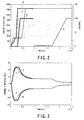
- Figs. 2 and 3 show the starting characteristics of thermal stress prediction starting when, using the turbine starting controller 10, the turbine acceleration rate/load increase rate (as the manipulated variable) in the prediction period is assumed to be constant, and the optimization calculation is simplified to one-variable calculation.
- Fig. 2 symbol “A” denotes the starting characteristic of turbine rpm under the thermal stress prediction starting control by the turbine starting controller 10, and symbol “B” denotes the starting characteristic of generator load under the thermal stress prediction starting control by the turbine starting controller 10.
- the both indicate that the starting time is significantly shortened in comparison to a starting characteristic curve "a” of turbine rpm for conventional turbine starting controllers and a steam turbine generator as represented by a generator load starting characteristic curve "b", which means that the starting characteristic of the steam turbine generator is significantly improved.
- thermal stress change curves C and D on the bore and rotor surface sides of the turbine rotor, respectively are little changed as compared with thermal stress change curves "c" and "d” on the bore and surface sides of the turbine rotor, respectively, of a conventional turbine starting controller with regard to the maximum value of the thermal stress.
- the prescribed value of the rotor surface thermal stress is set to, for example, -24.72 kg/mm 2 .
- the turbine starting control by the turbine starting controller 10 is performed as described below.
- the optimum starting controlling means 17 repeats the optimization calculation cycle in which a heat transfer predicting step, a first stage metal temperature predicting step, a thermal stress predicting step, and an optimization calculation step are repeated.
- the heat transfer rate hf(k+j) over the prediction period from the current time to the future is predicted from the measured plant state variables (turbine rpm ⁇ and generator load MW).
- the predicted heat transfer rate hf(k+j) from the heat transfer rate predicting means 22, the predicted first stage steam temperature T s (k+j) from the first stage steam temperature predicting means 21, and the measured value T met of the first stage metal temperature are input to thereby predict the first stage metal temperature T met (k+j) in the prediction period, and the rate of change ⁇ T met (k+j) thereof per one step is output to the thermal stress predicting step.
- the thermal stress predicting step the thermal stress ⁇ s (k+j) generated in the turbine rotor in the prediction period is predicted.
- the manipulated variable optimum transition pattern is calculated for each predetermined control period while keeping the thermal stress from the thermal stress predicting means 24 equal to or lower than a prescribed value under the constraint of the plant operating conditions.
- the value at the current time in the manipulated variable optimum transition pattern is determined as the actual optimum manipulated variable, and the value of the manipulated variable at the current time (k) in the manipulated variable optimum transition pattern is output from the optimization calculating means 25 to the rpm/load controlling means 18 in the form of a signal indicative of the optimum turbine acceleration rate ⁇ opt /load increase rate ⁇ MW opt as the optimum manipulated variable.
- the rpm/load controlling means 18 is input with the signal of the optimum manipulated variable to adjust and control the flow rate adjusting valve 13 as the control valve.
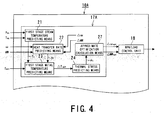
- Figs. 4 and 5 show a turbine starting controller and a starting control method for the turbine starting controller according to a second embodiment of the present invention.
- a turbine starting controller 10A In a turbine starting controller 10A according to the second embodiment, the optimization calculating means 25 included in the optimum starting controlling means 17 of the turbine starting controller 10 according to the first embodiment is replaced by approximate optimization calculating means 27. Otherwise, the turbine starting controller 10A is of substantially the same construction and operation as the turbine starting controller 10 according to the first embodiment, so that the same or like components are denoted by the same symbols and description thereof will be omitted.
- the approximate optimization calculating means 27 is included in optimum starting controlling means 17A, which outputs the optimum manipulated variables ⁇ opt and ⁇ MW opt to the rpm/load controlling means 18, so as to replace the optimization calculating means 25.
- the optimum starting controlling means 17A computes the optimum manipulated variables ⁇ ⁇ opt and ⁇ MW opt through straightforward operation without repeating an indefinite number of optimization calculation cycles, that is, without forming a repetitive calculation loop, and outputs them to the rpm/load controlling means 18 at a predetermined timing (control period).
- the maximum value ⁇ smax of the predicted thermal stress ⁇ s (k+j) in the prediction period is calculated by the thermal stress predicting means 24 via the heat transfer rate predicting means 22 and the first stage metal temperature predicting means 23.
- the approximate optimization calculating means 27 From the maximum value ⁇ smax of the predicted thermal stress ⁇ s calculated by the thermal stress predicting means 24, the approximate optimization calculating means 27 approximately computes, using the technique of linear interpolation or the like, the maximum value of the manipulated variable satisfying the condition that the maximum value ⁇ smax of the predicted thermal stress ⁇ s (k+j) be equal to or lower than the prescribed value.
- the approximate optimization calculating means 27 outputs the maximum value of the manipulated variable thus computed to the rpm/load controlling means 18 as the optimum manipulated variable (optimum turbine acceleration rate ⁇ opt /the optimum load increase rate ⁇ MW opt ) .
- manipulated variables at a plurality of, for example, five points are set such that preset turbine acceleration rates ⁇ at the five points consist of the following: [ Numerical Example 23 ] ⁇ ⁇ min ⁇ ⁇ ⁇ 1 ⁇ ⁇ ⁇ 2 ⁇ ⁇ ⁇ 3 ⁇ ⁇ ⁇ max
- the thermal stress ⁇ s (k+j) in the prediction period is predicted by the thermal stress predicting means 24 via the heat transfer rate predicting means 22 and the first stage metal temperature predicting means 23.
- Fig. 5 shows an example of a flowchart of the approximate optimization calculating means 27 for approximately calculating the optimum manipulated variable ⁇ opt/ ⁇ MWopt.
- the optimum manipulated variable ⁇ opt / ⁇ MW opt as an output value to the rpm/load controlling means 18 can be computed through straightforward operation without repeating an indefinite number of optimization calculation cycles in the manipulated variable optimization process.
- the maximum value ⁇ smax of the predicted thermal stress ⁇ s (k+j) is calculated by the thermal stress predicting means 24 via the heat transfer rate predicting means 22 and the first stage metal temperature predicting means 23.
- the approximate optimization calculating means 27 computes, for each control period and through linear interpolation, the approximate optimum manipulated variable ⁇ opt / ⁇ MW opt which realizes the shortest starting time while satisfying the condition that the maximum value of the predicted thermal stress ⁇ s (k+j) be equal to or lower than the prescribed value ⁇ smax , and outputs it to the rpm/load controlling means 18 (see Fig. 1).
- the optimum manipulated variable (the optimum turbine acceleration rate, the optimum load increase rate) can be calculated without repeating an indefinite number of optimization calculation cycles, and the manipulated variable optimization can be realized through straightforward operation.
- the turbine starting control in the turbine starting controller 10A can be performed by replacing the optimization calculation step in the turbine starting controller 10 according to the first embodiment with the approximate optimization calculation step.
- the optimum manipulated variable realizing the shortest starting time, while keeping the maximum value of the predicted thermal stress ⁇ s (k+j) equal to or lower than the prescribed value under the constraint of the plant operating conditions, is approximately calculated through deterministic operation for each control period, and the approximate optimum manipulated variable thus obtained is output to the rpm/load controlling means 18 as the optimum turbine acceleration rate ⁇ opt /load increase rate ⁇ MW opt .
- the rpm/load controlling means 18 performs drive control on the control valve 13 based on the approximate manipulated variable as the approximate optimum solution, thereby adjusting and controlling the valve opening to perform turbine starting control.
- the manipulated variable (turbine acceleration rate ⁇ , load increase rate ⁇ MW) in the optimization process is not output from the approximate optimization calculating means 27 to the heat transfer rate predicting means 22.
- the preset turbine acceleration rate ⁇ , load increase rate ⁇ MW as the assumed manipulated variable is input to the heat transfer rate predicting means 22.
- Fig. 6 shows a turbine starting controller and a starting control method thereof according to a third embodiment of the present invention.
- heat transfer rate prediction model modifying means 28 is additionally provided to the optimum starting controlling means 17 of the turbine starting controller 10 according to the first embodiment.
- the turbine starting controller 10B is of substantially the same construction and operation as the turbine starting controller 10 according to the first embodiment, so that the same or like components are denoted by the same symbols and description thereof will be omitted.
- the heat transfer rate prediction mode modifying means 28 is added to the optimum starting controlling means 17 according to the first embodiment to thereby obtain new optimum starting controlling means 17B.
- the prediction model of the heat transfer rate hf used in the heat transfer rate predicting means 22 which takes the manipulated variable as a variable is modified at real time.
- the heat transfer rate prediction model modifying means 28 modifies at real time the prediction model with the manipulated variable used in the heat transfer rate predicting means 22, based on the measured values of plant state variables such as the first state metal temperature T met for each control period.
- the heat transfer rate hf(k) at the current time k is calculated through inverse operation on the actual value basis as in the following expression.
- h f ( k ) ⁇ T met ( k ) T s ( k ⁇ 1 ) ⁇ T met ( k ⁇ 1 )
- the heat transfer rate hf(k) at the current time k is computed with accuracy through inverse operation from the actual basis for each control period.
- the accuracy of the heat transfer rate prediction model is maintained by using the highly accurate value of the model coefficient ⁇ .
- the heat transfer rate model modifying means 28 is added to the optimum starting controlling means 17B, and the coefficient ⁇ of the heat transfer rate prediction model is corrected for each control period on the actual value basis of plant state variables (P ms , T ms , ⁇ , MW, and T met ) by the heat transfer rate model modifying means 28, whereby the accuracy of the heat transfer rate prediction model can be maintained.
- the optimum starting controlling means 17B is provided with the heat transfer rate model modifying means 28, and the accuracy of the heat transfer rate prediction model used for the thermal stress prediction can be updated in real time by the heat transfer rate model modifying means 28 based on the measured values of the plant state variables, whereby the accuracy of thermal stress prediction can be improved.
- the shortest turbine starting time can be achieved while keeping the maximum value ⁇ smax of the thermal stress ⁇ s in the prediction period from the thermal stress predicting means 24 equal to or lower than the prescribed value ⁇ max , whereby an improvement can be achieved in terms of the accuracy of the optimum turbine starting control.
- Figs. 7 and 8 show a turbine starting controller and a starting control method thereof according to a fourth embodiment of the present invention.
- a turbine starting controller 10C according to the fourth embodiment has optimum starting control correcting means 30 provided between the optimum starting controlling means 17 and the rpm/load controlling means 18 that are provided to the turbine starting controller 10 according to the first embodiment.
- the optimum starting controlling means 17 used may be either one of the optimum starting controlling means 17A shown in Fig. 4 and the optimum starting controlling means 17B shown in Fig. 6.
- the turbine starting controller 10C shown in Fig. 7 the same components and functions as those of the turbine starting controller 10 according to the first embodiment are denoted by the same symbols and description thereof will be omitted.
- the optimum starting control correcting means 30 independent from the optimum starting controlling means 17 (17A, 17B) of the turbine starting controller 10 (10A, 10B) described above is added.
- the constraint conditions specific to a power plant which cannot be readily taken into account in the optimization calculation process by the optimum starting controlling means 17, are independently represented as the optimum starting control correcting means 30, thereby executing the optimum turbine starting control that takes into account the constraint conditions specific to the power plant.
- the turbine starting controller 10C on the basis of the constraint conditions concerning startup specific to the power plant, which have not been taken into account in the optimization calculation process by the optimum starting controlling means 17, the optimum turbine acceleration rate/optimum load increase rate as the optimum manipulated variable output by the optimum starting controlling means 17, or the starting schedule, is changed through control by the optimum starting control correcting means 30.
- Fig. 8 shows an example of correction logic used in the optimum starting control correcting means 30 provided independently from the optimum starting controlling means 17.
- the steam turbine 11 is subject to the constraint condition that, in order to avoid an increase in vibration at its mechanical resonance point, the HOLD on the turbine rpm be prohibited at rpm regions near the resonance point (critical rpm region) (the rpm region of, for example, 900 rpm to 3300 rpm when the rated rpm is 3600 rpm), and that at the critical rpm region, the rpm must be increased at a fixed turbine acceleration rate or more.
- critical rpm region the rpm region of, for example, 900 rpm to 3300 rpm when the rated rpm is 3600 rpm
- the optimization calculation process of the optimum starting controlling means 17 also incorporates constraint conditions relating to the turbine acceleration in the form of switching of the lower limit value of the manipulated variable.
- the optimum starting control correcting means 30 is independently provided on the output side of the optimum starting controlling means 17, and the "CRITICAL SPEED PERMIT" condition is configured as shown in Fig. 8A by the optimum starting control correcting means 30.
- the generator system incorporation permitting condition that is, the so-called "52G ON PERMIT" condition shown in Fig. 8B, is constituted as the optimum starting control correcting means 30.
- the optimum starting control correcting means 30 is provided on the output side of the optimum starting controlling means 17, and on the basis of the constraint conditions relating to start-up specific to the power plant, the starting schedule including the optimum turbine acceleration rate/optimum load increase rate and the like (as the optimum operating conditions) calculated by the optimum starting controlling means 17 is corrected by the optimum starting control correcting means 30 for modification control, thereby performing final turbine starting control.
- the constraint conditions specific to the power plant which cannot be readily taken into account in the optimization calculation process of the optimum starting controlling means 17 of the turbine starting controller 10C, are taken into account by the optimum starting control correcting means 30 that is independently provided, and the optimum starting control correcting means 30 corrects the optimum manipulated variables (the optimum turbine acceleration rate and the optimum load increase rate) from the optimum starting controlling means 17 on the basis of the constraint conditions specific to the power plant before outputting them to the rpm/load controlling means 18 (see Fig. 1) as the final optimum manipulated variables.
- the optimum starting control correcting means 30 is provided independently on the output side of the optimum starting controlling means 17, and the starting schedule including the optimum turbine acceleration rate/optimum load increase rate and the like output from the optimum starting controlling means 17 is corrected and subjected to modification control on the output side thereof by the optimum starting control correcting means 30 based on the constraint conditions specific to the power plant, whereby turbine starting control that takes into account the constraint conditions specific to the power plant can be realized.
- the turbine starting controller is also applicable to a gas turbine, and also to a combined-cycle power plant.
- the combustion flow rate or gas temperature is used as the plant state variable instead of the main steam flow rate or main steam temperature.
Landscapes
- Engineering & Computer Science (AREA)
- Mechanical Engineering (AREA)
- General Engineering & Computer Science (AREA)
- Chemical & Material Sciences (AREA)
- Combustion & Propulsion (AREA)
- Physics & Mathematics (AREA)
- Fluid Mechanics (AREA)
- Control Of Turbines (AREA)
Applications Claiming Priority (1)
| Application Number | Priority Date | Filing Date | Title |
|---|---|---|---|
| JP2005074344A JP4723884B2 (ja) | 2005-03-16 | 2005-03-16 | タービン起動制御装置およびその起動制御方法 |
Publications (3)
| Publication Number | Publication Date |
|---|---|
| EP1707757A2 true EP1707757A2 (fr) | 2006-10-04 |
| EP1707757A3 EP1707757A3 (fr) | 2008-12-03 |
| EP1707757B1 EP1707757B1 (fr) | 2013-08-28 |
Family
ID=36602438
Family Applications (1)
| Application Number | Title | Priority Date | Filing Date |
|---|---|---|---|
| EP06005292.5A Expired - Lifetime EP1707757B1 (fr) | 2005-03-16 | 2006-03-15 | Dispositif de contrôle du démarrage d'une turbine et méthode correspondante |
Country Status (4)
| Country | Link |
|---|---|
| US (1) | US7980053B2 (fr) |
| EP (1) | EP1707757B1 (fr) |
| JP (1) | JP4723884B2 (fr) |
| CN (1) | CN100416047C (fr) |
Cited By (5)
| Publication number | Priority date | Publication date | Assignee | Title |
|---|---|---|---|---|
| GB2541501A (en) * | 2015-07-01 | 2017-02-22 | Emerson Process Man Power & Water Solutions Inc | Methods and apparatus to optimize steam turbine ramp rates |
| EP2728145A3 (fr) * | 2012-11-05 | 2017-08-30 | General Electric Company | Systèmes et procédés permettant de produire une charge prévisible lors de l'exécution de la séquence de démarrage d'une turbine |
| EP2647811A4 (fr) * | 2010-11-30 | 2017-12-06 | Mitsubishi Hitachi Power Systems, Ltd. | Dispositif de commande de turbine à gaz et système de production d'énergie |
| US10781723B2 (en) | 2015-07-24 | 2020-09-22 | Emerson Process Management Power And Water Solutions, Inc. | Methods and apparatus to optimize steam header blending and gas turbine loading in combined cycle power plants |
| CN111706406A (zh) * | 2020-06-15 | 2020-09-25 | 华能罗源发电有限责任公司 | 一种快速中速暖机控制系统 |
Families Citing this family (41)
| Publication number | Priority date | Publication date | Assignee | Title |
|---|---|---|---|---|
| JP5080146B2 (ja) * | 2007-06-19 | 2012-11-21 | 株式会社小野測器 | エンジンの設計変数の最適解を計算する方法、コンピュータ、及びプログラム |
| JP4774028B2 (ja) * | 2007-10-12 | 2011-09-14 | 三菱重工業株式会社 | クローズドサイクルプラント |
| JP4928484B2 (ja) * | 2008-02-29 | 2012-05-09 | 株式会社小野測器 | エンジンの設計変数を計算する方法、コンピュータ、及びプログラム |
| RU2464436C2 (ru) | 2008-03-28 | 2012-10-20 | Мицубиси Хеви Индастрис, Лтд. | Способ управления турбинной установкой и турбинная установка |
| US8127557B2 (en) * | 2008-04-07 | 2012-03-06 | General Electric Company | Control systems and method for controlling a load point of a gas turbine engine |
| JP2009281248A (ja) | 2008-05-21 | 2009-12-03 | Toshiba Corp | タービンシステムおよびタービンシステム起動制御方法 |
| US8352148B2 (en) * | 2008-05-21 | 2013-01-08 | General Electric Company | System for controlling input profiles of combined cycle power generation system |
| JP4885199B2 (ja) * | 2008-11-21 | 2012-02-29 | 三菱重工業株式会社 | ガスタービン運転制御装置及び方法 |
| EP2216506A1 (fr) * | 2009-02-10 | 2010-08-11 | Siemens Aktiengesellschaft | Procédé de chauffage d'un arbre de turbine |
| EP2244011A1 (fr) * | 2009-03-24 | 2010-10-27 | Siemens AG | Procédé et dispositif de réglage de la température de la vapeur pour une centrale à vapeur |
| US8195339B2 (en) * | 2009-09-24 | 2012-06-05 | General Electric Company | System and method for scheduling startup of a combined cycle power generation system |
| JP5457805B2 (ja) * | 2009-11-26 | 2014-04-02 | 株式会社東芝 | 発電計画支援装置および方法 |
| US8555653B2 (en) * | 2009-12-23 | 2013-10-15 | General Electric Company | Method for starting a turbomachine |
| US8833085B2 (en) * | 2010-01-27 | 2014-09-16 | General Electric Company | System and method for gas turbine startup control |
| US9145833B2 (en) | 2010-05-25 | 2015-09-29 | General Electric Company | Gas turbine startup control |
| FR2977915B1 (fr) * | 2011-07-12 | 2018-11-16 | Safran Helicopter Engines | Procede de demarrage d'une turbomachine reduisant le balourd thermique |
| US9140192B2 (en) | 2012-01-11 | 2015-09-22 | Alstom Technology Ltd. | Startup method for large steam turbines |
| JP6037448B2 (ja) * | 2013-03-15 | 2016-12-07 | 三菱日立パワーシステムズ株式会社 | 蒸気タービン発電プラント |
| JP6067450B2 (ja) | 2013-03-27 | 2017-01-25 | 三菱日立パワーシステムズ株式会社 | 蒸気タービン発電プラント |
| JP6004484B2 (ja) * | 2013-03-29 | 2016-10-12 | 三菱日立パワーシステムズ株式会社 | 蒸気タービン発電プラント |
| JP6092723B2 (ja) | 2013-06-25 | 2017-03-08 | 三菱日立パワーシステムズ株式会社 | 蒸気タービンプラントの起動制御装置 |
| JP6295062B2 (ja) | 2013-11-07 | 2018-03-14 | 三菱日立パワーシステムズ株式会社 | 蒸気タービンプラント起動制御装置 |
| EP3015658A1 (fr) * | 2014-10-27 | 2016-05-04 | Siemens Aktiengesellschaft | Unité de réglage de turbine dotée d'un régulateur de contrainte thermique en tant que régulateur principal |
| CN104481704B (zh) * | 2014-12-10 | 2016-02-10 | 中国科学院工程热物理研究所 | 一种实现燃气轮机起动过程中燃料实时控制方法及装置 |
| JP6404743B2 (ja) | 2015-02-24 | 2018-10-17 | 株式会社東芝 | 発電計画支援装置および発電計画支援方法 |
| JP6498059B2 (ja) * | 2015-06-30 | 2019-04-10 | 三菱日立パワーシステムズ株式会社 | 起動制御装置 |
| JP6510923B2 (ja) * | 2015-07-23 | 2019-05-08 | 三菱日立パワーシステムズ株式会社 | 発電プラントの起動制御装置及び起動制御方法 |
| US10100679B2 (en) | 2015-08-28 | 2018-10-16 | General Electric Company | Control system for managing steam turbine rotor stress and method of use |
| JP6587957B2 (ja) * | 2016-02-25 | 2019-10-09 | 株式会社東芝 | 蒸気タービン起動支援システム |
| JP2017025930A (ja) * | 2016-10-27 | 2017-02-02 | 三菱日立パワーシステムズ株式会社 | 蒸気タービン発電プラント |
| KR101842370B1 (ko) * | 2016-12-05 | 2018-03-26 | 두산중공업 주식회사 | 복합화력발전소의 빠른 기동 제어 방법 및 시스템 |
| US10954824B2 (en) | 2016-12-19 | 2021-03-23 | General Electric Company | Systems and methods for controlling drum levels using flow |
| US10677102B2 (en) * | 2017-02-07 | 2020-06-09 | General Electric Company | Systems and methods for controlling machinery stress via temperature trajectory |
| EP3460202A1 (fr) * | 2017-09-22 | 2019-03-27 | Siemens Aktiengesellschaft | Réglage de turbine à vapeur |
| JP7215017B2 (ja) * | 2018-08-23 | 2023-01-31 | 横浜ゴム株式会社 | ゴム材料設計方法、ゴム材料設計装置、及びプログラム |
| EP3987363B1 (fr) | 2019-06-20 | 2024-07-31 | Tata Consultancy Services Limited | Procédé et système permettant d'optimiser le fonctionnement d'une turbine à gaz à cycle combiné |
| US11352901B2 (en) * | 2020-02-17 | 2022-06-07 | Emerson Process Management Power & Water Solutions | Methods and apparatus to determine material parameters of turbine rotors |
| US11428115B2 (en) * | 2020-09-25 | 2022-08-30 | General Electric Company | Control of rotor stress within turbomachine during startup operation |
| JP7519892B2 (ja) * | 2020-12-04 | 2024-07-22 | 三菱重工業株式会社 | 負荷調整方法、負荷調整装置、及びプログラム |
| JP2022160888A (ja) * | 2021-04-07 | 2022-10-20 | 株式会社東芝 | タービン制御装置、タービン制御方法、およびタービン制御プログラム |
| WO2025211424A1 (fr) * | 2024-04-04 | 2025-10-09 | 川崎重工業株式会社 | Procédé de commande et dispositif de commande pour moteur à turbine à gaz |
Citations (2)
| Publication number | Priority date | Publication date | Assignee | Title |
|---|---|---|---|---|
| US4215552A (en) | 1977-02-09 | 1980-08-05 | Alsthom-Atlantique | Method for the operation of a power generating assembly |
| JPH09317404A (ja) | 1996-05-23 | 1997-12-09 | Toshiba Corp | 蒸気タービン起動制御装置 |
Family Cites Families (15)
| Publication number | Priority date | Publication date | Assignee | Title |
|---|---|---|---|---|
| US3358450A (en) * | 1965-12-21 | 1967-12-19 | Combustion Eng | Method and apparatus for steam turbine startup |
| SE376961B (fr) * | 1967-09-11 | 1975-06-16 | Svenska Maskinverken Ab | |
| US3928972A (en) * | 1973-02-13 | 1975-12-30 | Westinghouse Electric Corp | System and method for improved steam turbine operation |
| JPS6059402B2 (ja) * | 1980-01-11 | 1985-12-25 | 株式会社日立製作所 | ロ−タ応力予測タ−ビン制御システム |
| US4320625A (en) * | 1980-04-30 | 1982-03-23 | General Electric Company | Method and apparatus for thermal stress controlled loading of steam turbines |
| JPS59226211A (ja) * | 1983-06-08 | 1984-12-19 | Hitachi Ltd | 火力プラント制御方法 |
| JPS62206203A (ja) * | 1986-03-07 | 1987-09-10 | Hitachi Ltd | 蒸気タ−ビン運転制御方法 |
| US5042246A (en) * | 1989-11-06 | 1991-08-27 | General Electric Company | Control system for single shaft combined cycle gas and steam turbine unit |
| US5018356A (en) * | 1990-10-10 | 1991-05-28 | Westinghouse Electric Corp. | Temperature control of a steam turbine steam to minimize thermal stresses |
| US5136848A (en) * | 1991-10-07 | 1992-08-11 | Westinghouse Electric Corp. | Method for predicting the optimum transition between constant and sliding pressure operation |
| US5333457A (en) * | 1991-10-07 | 1994-08-02 | Westinghouse Electric Corporation | Operation between valve points of a partial-arc admission turbine |
| US5433079A (en) * | 1994-03-08 | 1995-07-18 | General Electric Company | Automated steam turbine startup method and apparatus therefor |
| DE19506787B4 (de) * | 1995-02-27 | 2004-05-06 | Alstom | Verfahren zum Betrieb einer Dampfturbine |
| WO1998021451A1 (fr) | 1996-11-08 | 1998-05-22 | Siemens Aktiengesellschaft | Dispositif de commande de turbine et procede de regulation du cycle d'effort d'une turbine |
| EP1365110B1 (fr) * | 2002-05-22 | 2009-01-07 | Siemens Aktiengesellschaft | Procédé et dispositif pour l'exploitation d'une centrale à vapeur, en particulier en charge partielle |
-
2005
- 2005-03-16 JP JP2005074344A patent/JP4723884B2/ja not_active Expired - Lifetime
-
2006
- 2006-03-15 US US11/375,599 patent/US7980053B2/en active Active
- 2006-03-15 EP EP06005292.5A patent/EP1707757B1/fr not_active Expired - Lifetime
- 2006-03-16 CN CNB2006100718050A patent/CN100416047C/zh not_active Expired - Lifetime
Patent Citations (2)
| Publication number | Priority date | Publication date | Assignee | Title |
|---|---|---|---|---|
| US4215552A (en) | 1977-02-09 | 1980-08-05 | Alsthom-Atlantique | Method for the operation of a power generating assembly |
| JPH09317404A (ja) | 1996-05-23 | 1997-12-09 | Toshiba Corp | 蒸気タービン起動制御装置 |
Cited By (8)
| Publication number | Priority date | Publication date | Assignee | Title |
|---|---|---|---|---|
| EP2647811A4 (fr) * | 2010-11-30 | 2017-12-06 | Mitsubishi Hitachi Power Systems, Ltd. | Dispositif de commande de turbine à gaz et système de production d'énergie |
| EP2728145A3 (fr) * | 2012-11-05 | 2017-08-30 | General Electric Company | Systèmes et procédés permettant de produire une charge prévisible lors de l'exécution de la séquence de démarrage d'une turbine |
| GB2541501A (en) * | 2015-07-01 | 2017-02-22 | Emerson Process Man Power & Water Solutions Inc | Methods and apparatus to optimize steam turbine ramp rates |
| US10267182B2 (en) | 2015-07-01 | 2019-04-23 | Emerson Process Management Power & Water Solutions, Inc. | Methods and apparatus to optimize steam turbine ramp rates |
| GB2541501B (en) * | 2015-07-01 | 2021-03-10 | Emerson Process Man Power & Water Solutions Inc | Methods and apparatus to optimize steam turbine ramp rates |
| US10781723B2 (en) | 2015-07-24 | 2020-09-22 | Emerson Process Management Power And Water Solutions, Inc. | Methods and apparatus to optimize steam header blending and gas turbine loading in combined cycle power plants |
| US11391185B2 (en) | 2015-07-24 | 2022-07-19 | Emerson Process Management Power & Water Solutions, Inc. | Methods and apparatus to optimize steam header blending and gas turbine loading in combined cycle power plants |
| CN111706406A (zh) * | 2020-06-15 | 2020-09-25 | 华能罗源发电有限责任公司 | 一种快速中速暖机控制系统 |
Also Published As
| Publication number | Publication date |
|---|---|
| CN1834408A (zh) | 2006-09-20 |
| CN100416047C (zh) | 2008-09-03 |
| EP1707757A3 (fr) | 2008-12-03 |
| JP4723884B2 (ja) | 2011-07-13 |
| JP2006257925A (ja) | 2006-09-28 |
| US7980053B2 (en) | 2011-07-19 |
| US20060233637A1 (en) | 2006-10-19 |
| EP1707757B1 (fr) | 2013-08-28 |
Similar Documents
| Publication | Publication Date | Title |
|---|---|---|
| EP1707757B1 (fr) | Dispositif de contrôle du démarrage d'une turbine et méthode correspondante | |
| US8510013B2 (en) | Gas turbine shutdown | |
| JP3673017B2 (ja) | 蒸気タービン起動制御装置 | |
| US4320625A (en) | Method and apparatus for thermal stress controlled loading of steam turbines | |
| EP1316866B1 (fr) | Opération optimale d'une centrale électrique | |
| US4120159A (en) | Steam turbine control system and method of controlling the ratio of steam flow between under full-arc admission mode and under partial-arc admission mode | |
| JP7348126B2 (ja) | 制御装置、制御入力決定方法、及び制御入力決定プログラム | |
| US20090288416A1 (en) | Turbine system and method for starting-controlling turbine system | |
| US20030009241A1 (en) | Open-loop and closed-loop control method, and a control device for starting up and shutting down a process component of a technical process | |
| CN106485064B (zh) | 一种抽水蓄能机组水轮机工况智能开机方法 | |
| JP2000186508A (ja) | ガスタ―ビンエンジン中のクリアランスの制御と補償に用いられる方法及び装置 | |
| CN103046972B (zh) | 汽轮机单阀或多阀的一种非线性自动无扰切换方法 | |
| JP2014177929A (ja) | 蒸気タービン発電プラント | |
| US9885251B2 (en) | Method and apparatus for controlling modulated cooling of a gas turbine component | |
| US9964047B2 (en) | Gas turbine engine optimization control device | |
| CN103174523B (zh) | 一种燃气轮机转速预测保护控制方法 | |
| JP5501870B2 (ja) | ガスタービン | |
| RU2490492C1 (ru) | Способ управления газотурбинным двигателем и система для его осуществления | |
| JP2001193480A (ja) | ガスタービンの制御方法および制御装置 | |
| JP2008128086A (ja) | ガスタービンの吸気加熱制御装置 | |
| JP2011111959A (ja) | 発電計画支援装置および方法 | |
| JPH09242507A (ja) | 蒸気タービンの起動制御装置 | |
| US11125166B2 (en) | Control system, gas turbine, power generation plant, and method of controlling fuel temperature | |
| JP2006200493A (ja) | ランキンサイクル装置 | |
| JPS6397835A (ja) | ガスタ−ビン温度制御装置 |
Legal Events
| Date | Code | Title | Description |
|---|---|---|---|
| PUAI | Public reference made under article 153(3) epc to a published international application that has entered the european phase |
Free format text: ORIGINAL CODE: 0009012 |
|
| 17P | Request for examination filed |
Effective date: 20060315 |
|
| AK | Designated contracting states |
Kind code of ref document: A2 Designated state(s): AT BE BG CH CY CZ DE DK EE ES FI FR GB GR HU IE IS IT LI LT LU LV MC NL PL PT RO SE SI SK TR |
|
| AX | Request for extension of the european patent |
Extension state: AL BA HR MK YU |
|
| PUAL | Search report despatched |
Free format text: ORIGINAL CODE: 0009013 |
|
| AK | Designated contracting states |
Kind code of ref document: A3 Designated state(s): AT BE BG CH CY CZ DE DK EE ES FI FR GB GR HU IE IS IT LI LT LU LV MC NL PL PT RO SE SI SK TR |
|
| AX | Request for extension of the european patent |
Extension state: AL BA HR MK YU |
|
| 17Q | First examination report despatched |
Effective date: 20090226 |
|
| AKX | Designation fees paid |
Designated state(s): DE FR IT |
|
| GRAP | Despatch of communication of intention to grant a patent |
Free format text: ORIGINAL CODE: EPIDOSNIGR1 |
|
| RIN1 | Information on inventor provided before grant (corrected) |
Inventor name: NAKAI, AKIMASA Inventor name: YAKUSHI, KOJI |
|
| GRAS | Grant fee paid |
Free format text: ORIGINAL CODE: EPIDOSNIGR3 |
|
| GRAA | (expected) grant |
Free format text: ORIGINAL CODE: 0009210 |
|
| AK | Designated contracting states |
Kind code of ref document: B1 Designated state(s): DE FR IT |
|
| REG | Reference to a national code |
Ref country code: DE Ref legal event code: R096 Ref document number: 602006038071 Country of ref document: DE Effective date: 20131024 |
|
| REG | Reference to a national code |
Ref country code: DE Ref legal event code: R097 Ref document number: 602006038071 Country of ref document: DE |
|
| PLBE | No opposition filed within time limit |
Free format text: ORIGINAL CODE: 0009261 |
|
| STAA | Information on the status of an ep patent application or granted ep patent |
Free format text: STATUS: NO OPPOSITION FILED WITHIN TIME LIMIT |
|
| 26N | No opposition filed |
Effective date: 20140530 |
|
| REG | Reference to a national code |
Ref country code: DE Ref legal event code: R097 Ref document number: 602006038071 Country of ref document: DE Effective date: 20140530 |
|
| REG | Reference to a national code |
Ref country code: FR Ref legal event code: PLFP Year of fee payment: 11 |
|
| REG | Reference to a national code |
Ref country code: FR Ref legal event code: PLFP Year of fee payment: 12 |
|
| REG | Reference to a national code |
Ref country code: FR Ref legal event code: PLFP Year of fee payment: 13 |
|
| PGFP | Annual fee paid to national office [announced via postgrant information from national office to epo] |
Ref country code: FR Payment date: 20241231 Year of fee payment: 20 |
|
| PGFP | Annual fee paid to national office [announced via postgrant information from national office to epo] |
Ref country code: DE Payment date: 20241231 Year of fee payment: 20 |
|
| PGFP | Annual fee paid to national office [announced via postgrant information from national office to epo] |
Ref country code: IT Payment date: 20250211 Year of fee payment: 20 |
|
| REG | Reference to a national code |
Ref country code: DE Ref legal event code: R071 Ref document number: 602006038071 Country of ref document: DE |