EP1707868A2 - Feu de signalisation, en particulier pour un environnement extérieur exposé aux intempéries - Google Patents
Feu de signalisation, en particulier pour un environnement extérieur exposé aux intempéries Download PDFInfo
- Publication number
- EP1707868A2 EP1707868A2 EP06005702A EP06005702A EP1707868A2 EP 1707868 A2 EP1707868 A2 EP 1707868A2 EP 06005702 A EP06005702 A EP 06005702A EP 06005702 A EP06005702 A EP 06005702A EP 1707868 A2 EP1707868 A2 EP 1707868A2
- Authority
- EP
- European Patent Office
- Prior art keywords
- signal light
- heating device
- heating
- dome
- light according
- Prior art date
- Legal status (The legal status is an assumption and is not a legal conclusion. Google has not performed a legal analysis and makes no representation as to the accuracy of the status listed.)
- Granted
Links
Images
Classifications
-
- F—MECHANICAL ENGINEERING; LIGHTING; HEATING; WEAPONS; BLASTING
- F21—LIGHTING
- F21S—NON-PORTABLE LIGHTING DEVICES; SYSTEMS THEREOF; VEHICLE LIGHTING DEVICES SPECIALLY ADAPTED FOR VEHICLE EXTERIORS
- F21S8/00—Lighting devices intended for fixed installation
-
- F—MECHANICAL ENGINEERING; LIGHTING; HEATING; WEAPONS; BLASTING
- F21—LIGHTING
- F21W—INDEXING SCHEME ASSOCIATED WITH SUBCLASSES F21K, F21L, F21S and F21V, RELATING TO USES OR APPLICATIONS OF LIGHTING DEVICES OR SYSTEMS
- F21W2111/00—Use or application of lighting devices or systems for signalling, marking or indicating, not provided for in codes F21W2102/00 – F21W2107/00
- F21W2111/06—Use or application of lighting devices or systems for signalling, marking or indicating, not provided for in codes F21W2102/00 – F21W2107/00 for aircraft runways or the like
-
- F—MECHANICAL ENGINEERING; LIGHTING; HEATING; WEAPONS; BLASTING
- F21—LIGHTING
- F21Y—INDEXING SCHEME ASSOCIATED WITH SUBCLASSES F21K, F21L, F21S and F21V, RELATING TO THE FORM OR THE KIND OF THE LIGHT SOURCES OR OF THE COLOUR OF THE LIGHT EMITTED
- F21Y2115/00—Light-generating elements of semiconductor light sources
- F21Y2115/10—Light-emitting diodes [LED]
Definitions
- the invention relates to a signal light, in particular exposed to the weather outside area, according to the preamble of claim 1.
- Signal lights of various kinds are used both outdoors and inside buildings for a variety of purposes. For example, signal lights for firing of taxiways, landing and / or runways as a fire or obstruction lights, as signal lights on buildings such. Airports, skyscrapers, towers, etc., used as alarm signal lights on buildings or access gates, etc., as warning lights for electricity pylons, transmission towers, television towers or on vehicles that are at least temporarily outdoors.
- a disadvantage of such signal lights is that they are exposed to the weather conditions and thereby the signaling or the emission of the signal light can be impaired.
- the object of the invention is the contrast, to propose a signal light, especially exposed to the weather outside area, with at least one light emitting element for generating a signal light whose signal light is reliably perceptible even in adverse climatic conditions.
- an indicator light according to the invention is characterized in that at least one heating device separate from the lighting element is provided for heating at least part of the signal light.
- the heating device according to the invention With the aid of the heating device according to the invention, ice and / or snow and / or frost and / or dew or fog attached to the signal light can be effectively removed in an elegant manner. This ensures that even with corresponding unfavorable climatic conditions, the signal light can be emitted without appreciable impairment.
- a heating device according to the preamble of claim 1 to provide a scraper device, in particular on the outside of the Signal light or is arranged on a portion of the signal light.
- a wiper unit or the like could effectively strip or eliminate fogging, dew, snow or the like, so that the object according to the invention could also be solved with the aid of this measure.
- the invention is also conceivable to heat electronic components or the like using the heater according to the invention, so that even extremely low temperatures do not lead to failure of corresponding components.
- the reliability of the signal light is ensured according to the invention, even in particularly cold climatic conditions effectively.
- the heating device is designed for heating the luminous element.
- This measure is particularly in signal lights without dome or the like of particular advantage, since with appropriately trained signal lights snow, ice or the like would deposit directly on the luminous element, but this can be effectively compensated according to this variant of the invention.
- a cap is provided for covering and / or protecting the luminous element.
- the lighting element can be effectively protected against mechanical deterioration or the like.
- the dome can be designed for advantageous signal propagation or for signal light steering, whereby the emission of the signal light can be further improved.
- the heating device is designed to heat at least a portion of the dome. This ensures that, for example, on the dome depositing snow, ice, frost, dew or fog or can be effectively eliminated by means of the heating device according to the invention. As a result, the safe operation of the signal light is guaranteed.
- the heating device is arranged on the outside of the luminous element and / or the outside of the dome. This could be an immediate elimination of ice or snow, etc. realized.
- the heating device is arranged in the interior of the dome.
- an effective protection of the heater for example, against mechanical impairment, abrasion or the like can be implemented.
- the entire interior can be heated advantageously, resulting in a more even heat distribution in the interior and / or on the dome.
- the heating device may have comparatively small or comparatively small heating surfaces, without the secure removal of ice and snow, etc. along large-area areas, e.g. the dome would be affected.
- a particularly inconspicuous and / or the emission of the signal light little impairing heating device can be realized according to the invention.
- the heating device may use a fuel such as e.g. Natural gas, hydrogen or the like, which is (catalytically) oxidized or burned and thus generates the advantageous heat for heating the signal light.
- a fuel such as e.g. Natural gas, hydrogen or the like, which is (catalytically) oxidized or burned and thus generates the advantageous heat for heating the signal light.
- the heating device is designed as an electrical heating resistor. Often signal lights already have an electrical power supply for the supply of the electric lighting element. With this measure, the design effort for supplying energy to the heater according to the invention is reducible.
- an electrical heating resistor is particularly easy ausgestaltbar. For example, it is possible to resort to already commercially available electrical heating resistors. This leads to an economically favorable implementation of the invention.
- the heating device is designed as a metal heating wire.
- Corresponding heating wires that means in particular a comparatively thin and at the same time long wire or line-shaped heating element, impair in particular the propagation of the signal light particularly little.
- the heating device has numerous metallic heating wires and / or electrical heating resistors.
- an advantageous distribution of the heating device on the area to be heated of the signal light or the dome can be realized.
- the heater is designed as a covering of the dome.
- the coating is arranged on the inside, in particular on the inner surface of the dome, whereby, inter alia, a mechanical protection of Schubelages is realized.
- the coating is applied by means of vapor deposition, spraying, brushing, printing or the like on the calotte.
- any desired pattern can be produced with this method, which in particular advantageously influences the areal distribution of the heating device.
- it is a covering, which is designed as a metallic heating wire or electrical heating resistor. This makes a particularly simple realization of the heating device according to the invention possible.
- the heating device is arranged within the dome wall. This means, for example, that the heater is in the dome wall. As a result, the heater is particularly effectively protected by the dome. Neither from the inside nor from the outside, such a trained heating device is advantageously accessible directly, which means a particularly good mechanical protection of the heater. As a result, for example, particularly thin heating lines or heating wires can be realized, which do not affect the radiation of the signal light.
- a fan for generating an air movement is provided.
- the heat circulation can be further improved, in particular in the interior of the signal light, which can lead to an advantageous distribution of heat and / or heating of the signal light or the dome.
- the dome can be made essentially of glass or plastic, whereby the emission of the signal light can be carried out in an advantageous manner.
- a crystal clear dome and / or an at least partially colored dome can be provided.
- At least one sensor for detecting a thermal and / or optical parameter is provided.
- the temperature of the signal light and / or the environment can be detected with the aid of a thermal sensor.
- an optical sensor for example, the light intensity in the signal light or outside of this can be detected.
- the detected parameters can be made available, for example, to a control unit which, on the basis of the sensor parameters determined, for example, determines whether there is a risk that frost will occur or frost, ice, snow or the like could affect the radiation of the signal light and / or whether a freeze of the electronics or the like would be possible and / or whether snow, frost or the like has accumulated or deposited on the signal light.
- a control unit is provided for controlling the operation of the heating device as a function of the parameter detected by the sensor.
- control unit can automatically put the heating device according to the invention into operation. If, for example, the light conditions in the interior of the signal light and / or the temperature change, for example, the heating device can be put out of operation with the aid of the control unit. Alternatively or in combination with this, a manual switching on and / or off of the heating device according to the invention can also take place.
- the luminous element is designed as a light bulb or halogen bulb, etc.
- the luminous element is designed as a light-emitting diode or light-emitting diode array, etc.
- Corresponding light-emitting diodes are characterized on the one hand their long life and low energy consumption. Accordingly, an economically favorable operation of the signal light according to the invention can be realized. However, since LEDs emit comparatively little heat, a special heating device according to the invention is particularly advantageous.
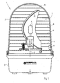
- Figure 1 shows schematically a signal lamp with a heating device according to the invention.
- the signal light according to FIG. 1 has a housing 1, which is designed in two parts and comprises a calotte 2 and a base part 3.
- the dome 2 is made for example of colored plastic or glass, which is translucent.
- the base part 3 of the housing 1 can be made of opaque plastic or the like.
- the two housing parts 2, 3 are for example detachable, pluggable, in particular by means of a screw thread or bayonet closure or the like, connectable.
- a flash and / or halogen bulb 4 for generating the signal light available.
- the halogen bulb 4 for example, one or more light-emitting diodes for generating the signal light could be provided in an advantageous manner.
- a reflector 5 is provided, which is preferably rotatable about an axis of rotation 6 is formed.
- a drive in particular an electric motor, can be provided, which can rotate the reflector 5 with or without the luminous element 4.
- a reflector 5 could be designed to be non-rotatable, which thus only realizes a static steering function or directional function with respect to the emission of the signal light.
- a heating device 7 is provided.
- the heating device 7 has numerous heating wires 8, which were preferably vapor-deposited as metallic heating wires 8 on the inner surface of the cap 2. All heating wires 8 are electrically connected to each other in an advantageous manner and are supplied via a contact unit 9 in a manner not shown with electrical energy.
- the contacting of the heating device 7 or the contact unit 9 with the electrical power supply such. an electrical connection cable and / or an electrical energy storage during or by the joining of the two housing parts 2 and 3.
- the contact unit 9 can be formed resilient and / or latching, so that a particularly secure power supply is ensured.
- a detection can be provided, which determines whether with the help of the heater 7 should be heated.
- a photoelement could detect darkening by snow cover or the like.
- a temperature sensor could detect the risk of icing.
- the heater 7 according to the invention advantageously, for the purpose of the visibility of the signal light under any weather conditions such as icing or heavy snowfall, etc., the heater 7 according to the invention can be used.
- special applications for example, obstruction lights, signal lights at airports, but also alarm signal lights in the open, which should not be allowed or cut to the extent possible, so that the signaled alarm or operating state is visible.
- the signal light can be formed according to the invention as a signal tower with at least one removable module.
- the exchange module preferably has the heating device 7.
Landscapes
- Engineering & Computer Science (AREA)
- General Engineering & Computer Science (AREA)
- Arrangement Of Elements, Cooling, Sealing, Or The Like Of Lighting Devices (AREA)
- Led Device Packages (AREA)
- Resistance Heating (AREA)
Applications Claiming Priority (1)
| Application Number | Priority Date | Filing Date | Title |
|---|---|---|---|
| DE102005014817A DE102005014817A1 (de) | 2005-03-30 | 2005-03-30 | Signalleuchte, insbesondere für den Wetter ausgesetzten Außenbereich |
Publications (3)
| Publication Number | Publication Date |
|---|---|
| EP1707868A2 true EP1707868A2 (fr) | 2006-10-04 |
| EP1707868A3 EP1707868A3 (fr) | 2008-04-02 |
| EP1707868B1 EP1707868B1 (fr) | 2010-01-20 |
Family
ID=36608624
Family Applications (1)
| Application Number | Title | Priority Date | Filing Date |
|---|---|---|---|
| EP06005702A Ceased EP1707868B1 (fr) | 2005-03-30 | 2006-03-21 | Feu de signalisation, en particulier pour un environnement extérieur exposé aux intempéries |
Country Status (2)
| Country | Link |
|---|---|
| EP (1) | EP1707868B1 (fr) |
| DE (2) | DE102005014817A1 (fr) |
Cited By (3)
| Publication number | Priority date | Publication date | Assignee | Title |
|---|---|---|---|---|
| CN102052586A (zh) * | 2009-10-29 | 2011-05-11 | 富准精密工业(深圳)有限公司 | 灯具 |
| CN102289945A (zh) * | 2010-06-18 | 2011-12-21 | 展晶科技(深圳)有限公司 | 交通信号灯具 |
| WO2014151498A1 (fr) | 2013-03-15 | 2014-09-25 | Cooper Technologies Company | Éléments chauffants pour des surfaces émettant des ondes électromagnétiques |
Families Citing this family (2)
| Publication number | Priority date | Publication date | Assignee | Title |
|---|---|---|---|---|
| DE202006017564U1 (de) * | 2006-11-17 | 2008-03-27 | Winter, Josef | Beleuchtungsvorrichtung oder Signalleuchte für den Aussenbereich, sowie Heizvorrichtung hierfür |
| DE102013110365A1 (de) * | 2013-09-19 | 2015-03-19 | Lars Hohaus | Befeuerungsleuchte zur Befeuerung einer Windenergieanlage, insbesondere eines Turms einer Windenergieanlage |
Citations (3)
| Publication number | Priority date | Publication date | Assignee | Title |
|---|---|---|---|---|
| US3207893A (en) | 1963-02-07 | 1965-09-21 | Nado Joseph | Fluorescent patio lamp and the like |
| WO1999060304A1 (fr) | 1998-05-18 | 1999-11-25 | Industrial Manufacturing And Trading B.V. | Appareil d'eclairage antideflagrant de type securite |
| US6352358B1 (en) | 1998-11-11 | 2002-03-05 | Tempest Lighting, Inc. | Universally positionable climate controlled light enclosure |
Family Cites Families (4)
| Publication number | Priority date | Publication date | Assignee | Title |
|---|---|---|---|---|
| GB9601865D0 (en) * | 1996-01-30 | 1996-04-03 | Pilkington Glass Ltd | Electrically heated window |
| DE19823124B4 (de) * | 1998-05-23 | 2006-02-09 | Adam Opel Ag | Verbundglasscheibe für Kraftfahrzeuge |
| DE19963337A1 (de) * | 1999-12-27 | 2001-07-12 | Hella Kg Hueck & Co | Beleuchtungsvorrichtung für Fahrzeuge |
| AT500634B8 (de) * | 2002-12-20 | 2007-02-15 | Zizala Lichtsysteme Gmbh | Fahrzeugscheinwerfer mit heizung |
-
2005
- 2005-03-30 DE DE102005014817A patent/DE102005014817A1/de not_active Withdrawn
-
2006
- 2006-03-21 EP EP06005702A patent/EP1707868B1/fr not_active Ceased
- 2006-03-21 DE DE502006005950T patent/DE502006005950D1/de not_active Expired - Lifetime
Patent Citations (3)
| Publication number | Priority date | Publication date | Assignee | Title |
|---|---|---|---|---|
| US3207893A (en) | 1963-02-07 | 1965-09-21 | Nado Joseph | Fluorescent patio lamp and the like |
| WO1999060304A1 (fr) | 1998-05-18 | 1999-11-25 | Industrial Manufacturing And Trading B.V. | Appareil d'eclairage antideflagrant de type securite |
| US6352358B1 (en) | 1998-11-11 | 2002-03-05 | Tempest Lighting, Inc. | Universally positionable climate controlled light enclosure |
Cited By (4)
| Publication number | Priority date | Publication date | Assignee | Title |
|---|---|---|---|---|
| CN102052586A (zh) * | 2009-10-29 | 2011-05-11 | 富准精密工业(深圳)有限公司 | 灯具 |
| CN102289945A (zh) * | 2010-06-18 | 2011-12-21 | 展晶科技(深圳)有限公司 | 交通信号灯具 |
| WO2014151498A1 (fr) | 2013-03-15 | 2014-09-25 | Cooper Technologies Company | Éléments chauffants pour des surfaces émettant des ondes électromagnétiques |
| EP2971943A4 (fr) * | 2013-03-15 | 2016-11-09 | Cooper Technologies Co | Éléments chauffants pour des surfaces émettant des ondes électromagnétiques |
Also Published As
| Publication number | Publication date |
|---|---|
| EP1707868A3 (fr) | 2008-04-02 |
| DE102005014817A1 (de) | 2006-10-05 |
| DE502006005950D1 (de) | 2010-03-11 |
| EP1707868B1 (fr) | 2010-01-20 |
Similar Documents
| Publication | Publication Date | Title |
|---|---|---|
| EP3425999B1 (fr) | Agencement de vitre doté d'un écran anti-lumière diffusée chauffé électriquement | |
| EP2208926A1 (fr) | Module de lampe doté d'un garnissage DEL | |
| DE202012005908U1 (de) | Abdeckscheibe für eine Beleuchtungseinrichtung mit einerEnteisungseinrichtung und Beleuchtungseinrichtung mit einer Enteisungseinrichtung | |
| DE102011084114A1 (de) | Kraftfahrzeugscheinwerfer | |
| EP1707868B1 (fr) | Feu de signalisation, en particulier pour un environnement extérieur exposé aux intempéries | |
| DE102011001867A1 (de) | Mittel zur Enttauung der Abschlussscheibe | |
| DE102012010871A1 (de) | Vorrichtung und Verfahren zur Enttauung einer Beleuchtungseinheit und Beleuchtungseinheit mit einer solchen Vorrichtung | |
| DE102004046764A1 (de) | Fahrzeugscheinwerfer | |
| EP1869366B1 (fr) | Phare | |
| DE10331835A1 (de) | Leuchte für ein Fahrzeug mit einer Betauungsschutzvorrichtung | |
| EP2131101A1 (fr) | Lampe | |
| EP3037721A1 (fr) | Dispositif d'éclairage commandé par capteur | |
| DE102013110857A1 (de) | Befeuerungsleuchte zur Befeuerung einer Windenergieanlage, insbesondere eines Turms einer Windenergieanlage | |
| DE102020007598A1 (de) | Scheinwerfer mit einer beheizbaren Abdeckscheibe und Verfahren zum Betreiben des Scheinwerfers | |
| DE2645231A1 (de) | Beheizbare oberflaechen, insbesondere rueckblickspiegel | |
| DE4021992A1 (de) | Vorrichtung mit einer zu beheizenden flaeche, insbesondere beheizbarer kraftfahrzeug-aussenrueckspiegel | |
| DE10319363A1 (de) | Leuchtvorrichtung für Fahrzeuge und Verfahren zum Steuern und/oder Regeln einer Betauungsschutzvorrichtung einer Leuchtvorrichtung für Fahrzeuge | |
| DE102015208195A1 (de) | Kochfeld mit mindestens einer Halbleiterlichtquelle und Lichtstreukörper | |
| DE102012006678A1 (de) | Heizvorrichtung für eine Abdeckscheibe einer Fahrzeugleuchte und Fahrzeugleuchte mit einer Heizvorrichtung | |
| DE10340073A1 (de) | Fahrzeugleuchte | |
| DE102009006220B4 (de) | Enttauungsvorrichtung für Lichteinheiten | |
| EP2405716B1 (fr) | Moyen d'éclairage et son procédé d'alimentation en courant | |
| DE102005042797B4 (de) | Signalgeber für eine Lichtsignalanlage | |
| DE102016202040A1 (de) | Fahrzeugaußenspiegelanordnung | |
| DE10258049B4 (de) | Fahrzeugleuchte |
Legal Events
| Date | Code | Title | Description |
|---|---|---|---|
| PUAI | Public reference made under article 153(3) epc to a published international application that has entered the european phase |
Free format text: ORIGINAL CODE: 0009012 |
|
| AK | Designated contracting states |
Kind code of ref document: A2 Designated state(s): AT BE BG CH CY CZ DE DK EE ES FI FR GB GR HU IE IS IT LI LT LU LV MC NL PL PT RO SE SI SK TR |
|
| AX | Request for extension of the european patent |
Extension state: AL BA HR MK YU |
|
| PUAL | Search report despatched |
Free format text: ORIGINAL CODE: 0009013 |
|
| AK | Designated contracting states |
Kind code of ref document: A3 Designated state(s): AT BE BG CH CY CZ DE DK EE ES FI FR GB GR HU IE IS IT LI LT LU LV MC NL PL PT RO SE SI SK TR |
|
| AX | Request for extension of the european patent |
Extension state: AL BA HR MK YU |
|
| 17P | Request for examination filed |
Effective date: 20080815 |
|
| AKX | Designation fees paid |
Designated state(s): DE FR GB IT |
|
| 17Q | First examination report despatched |
Effective date: 20081210 |
|
| RAP1 | Party data changed (applicant data changed or rights of an application transferred) |
Owner name: WERMA HOLDING GMBH + CO. KG |
|
| GRAP | Despatch of communication of intention to grant a patent |
Free format text: ORIGINAL CODE: EPIDOSNIGR1 |
|
| GRAS | Grant fee paid |
Free format text: ORIGINAL CODE: EPIDOSNIGR3 |
|
| GRAA | (expected) grant |
Free format text: ORIGINAL CODE: 0009210 |
|
| AK | Designated contracting states |
Kind code of ref document: B1 Designated state(s): DE FR GB IT |
|
| REG | Reference to a national code |
Ref country code: GB Ref legal event code: FG4D Free format text: NOT ENGLISH |
|
| REF | Corresponds to: |
Ref document number: 502006005950 Country of ref document: DE Date of ref document: 20100311 Kind code of ref document: P |
|
| PLBE | No opposition filed within time limit |
Free format text: ORIGINAL CODE: 0009261 |
|
| STAA | Information on the status of an ep patent application or granted ep patent |
Free format text: STATUS: NO OPPOSITION FILED WITHIN TIME LIMIT |
|
| 26N | No opposition filed |
Effective date: 20101021 |
|
| REG | Reference to a national code |
Ref country code: FR Ref legal event code: PLFP Year of fee payment: 11 |
|
| REG | Reference to a national code |
Ref country code: FR Ref legal event code: PLFP Year of fee payment: 12 |
|
| REG | Reference to a national code |
Ref country code: FR Ref legal event code: PLFP Year of fee payment: 13 |
|
| PGFP | Annual fee paid to national office [announced via postgrant information from national office to epo] |
Ref country code: DE Payment date: 20240321 Year of fee payment: 19 Ref country code: GB Payment date: 20240322 Year of fee payment: 19 |
|
| PGFP | Annual fee paid to national office [announced via postgrant information from national office to epo] |
Ref country code: IT Payment date: 20240329 Year of fee payment: 19 Ref country code: FR Payment date: 20240320 Year of fee payment: 19 |
|
| REG | Reference to a national code |
Ref country code: DE Ref legal event code: R082 Ref document number: 502006005950 Country of ref document: DE Representative=s name: RAVENSPAT PATENTANWAELTE PARTNERSCHAFT MBB, DE |
|
| REG | Reference to a national code |
Ref country code: DE Ref legal event code: R119 Ref document number: 502006005950 Country of ref document: DE |
|
| GBPC | Gb: european patent ceased through non-payment of renewal fee |
Effective date: 20250321 |
|
| PG25 | Lapsed in a contracting state [announced via postgrant information from national office to epo] |
Ref country code: DE Free format text: LAPSE BECAUSE OF NON-PAYMENT OF DUE FEES Effective date: 20251001 |
|
| PG25 | Lapsed in a contracting state [announced via postgrant information from national office to epo] |
Ref country code: GB Free format text: LAPSE BECAUSE OF NON-PAYMENT OF DUE FEES Effective date: 20250321 |
|
| PG25 | Lapsed in a contracting state [announced via postgrant information from national office to epo] |
Ref country code: FR Free format text: LAPSE BECAUSE OF NON-PAYMENT OF DUE FEES Effective date: 20250331 Ref country code: IT Free format text: LAPSE BECAUSE OF NON-PAYMENT OF DUE FEES Effective date: 20250321 |