EP1707894A1 - Climatiseur - Google Patents
Climatiseur Download PDFInfo
- Publication number
- EP1707894A1 EP1707894A1 EP06250434A EP06250434A EP1707894A1 EP 1707894 A1 EP1707894 A1 EP 1707894A1 EP 06250434 A EP06250434 A EP 06250434A EP 06250434 A EP06250434 A EP 06250434A EP 1707894 A1 EP1707894 A1 EP 1707894A1
- Authority
- EP
- European Patent Office
- Prior art keywords
- panel
- air conditioner
- indoor
- air
- front cover
- Prior art date
- Legal status (The legal status is an assumption and is not a legal conclusion. Google has not performed a legal analysis and makes no representation as to the accuracy of the status listed.)
- Granted
Links
- 239000003507 refrigerant Substances 0.000 claims description 15
- 238000003780 insertion Methods 0.000 claims description 2
- 230000037431 insertion Effects 0.000 claims description 2
- 239000004973 liquid crystal related substance Substances 0.000 claims description 2
- 230000004888 barrier function Effects 0.000 description 5
- 239000007788 liquid Substances 0.000 description 4
- 230000008901 benefit Effects 0.000 description 3
- 230000008859 change Effects 0.000 description 2
- 230000006835 compression Effects 0.000 description 2
- 238000007906 compression Methods 0.000 description 2
- 238000005034 decoration Methods 0.000 description 2
- 238000007599 discharging Methods 0.000 description 2
- 238000001704 evaporation Methods 0.000 description 2
- 230000008020 evaporation Effects 0.000 description 2
- 238000005057 refrigeration Methods 0.000 description 2
- 206010014405 Electrocution Diseases 0.000 description 1
- 208000027418 Wounds and injury Diseases 0.000 description 1
- 238000004378 air conditioning Methods 0.000 description 1
- 238000001816 cooling Methods 0.000 description 1
- 230000006378 damage Effects 0.000 description 1
- 239000000428 dust Substances 0.000 description 1
- 208000014674 injury Diseases 0.000 description 1
- 238000009434 installation Methods 0.000 description 1
- 238000004519 manufacturing process Methods 0.000 description 1
- 238000000034 method Methods 0.000 description 1
- 238000012986 modification Methods 0.000 description 1
- 230000004048 modification Effects 0.000 description 1
- 230000002093 peripheral effect Effects 0.000 description 1
- 230000009467 reduction Effects 0.000 description 1
- 230000035939 shock Effects 0.000 description 1
- 239000012780 transparent material Substances 0.000 description 1
Images




Classifications
-
- F—MECHANICAL ENGINEERING; LIGHTING; HEATING; WEAPONS; BLASTING
- F24—HEATING; RANGES; VENTILATING
- F24F—AIR-CONDITIONING; AIR-HUMIDIFICATION; VENTILATION; USE OF AIR CURRENTS FOR SCREENING
- F24F1/00—Room units for air-conditioning, e.g. separate or self-contained units or units receiving primary air from a central station
- F24F1/02—Self-contained room units for air-conditioning, i.e. with all apparatus for treatment installed in a common casing
- F24F1/022—Self-contained room units for air-conditioning, i.e. with all apparatus for treatment installed in a common casing comprising a compressor cycle
- F24F1/027—Self-contained room units for air-conditioning, i.e. with all apparatus for treatment installed in a common casing comprising a compressor cycle mounted in wall openings, e.g. in windows
-
- F—MECHANICAL ENGINEERING; LIGHTING; HEATING; WEAPONS; BLASTING
- F24—HEATING; RANGES; VENTILATING
- F24F—AIR-CONDITIONING; AIR-HUMIDIFICATION; VENTILATION; USE OF AIR CURRENTS FOR SCREENING
- F24F1/00—Room units for air-conditioning, e.g. separate or self-contained units or units receiving primary air from a central station
-
- F—MECHANICAL ENGINEERING; LIGHTING; HEATING; WEAPONS; BLASTING
- F24—HEATING; RANGES; VENTILATING
- F24F—AIR-CONDITIONING; AIR-HUMIDIFICATION; VENTILATION; USE OF AIR CURRENTS FOR SCREENING
- F24F13/00—Details common to, or for air-conditioning, air-humidification, ventilation or use of air currents for screening
- F24F13/20—Casings or covers
-
- F—MECHANICAL ENGINEERING; LIGHTING; HEATING; WEAPONS; BLASTING
- F24—HEATING; RANGES; VENTILATING
- F24F—AIR-CONDITIONING; AIR-HUMIDIFICATION; VENTILATION; USE OF AIR CURRENTS FOR SCREENING
- F24F11/00—Control or safety arrangements
- F24F11/50—Control or safety arrangements characterised by user interfaces or communication
- F24F11/52—Indication arrangements, e.g. displays
-
- F—MECHANICAL ENGINEERING; LIGHTING; HEATING; WEAPONS; BLASTING
- F24—HEATING; RANGES; VENTILATING
- F24F—AIR-CONDITIONING; AIR-HUMIDIFICATION; VENTILATION; USE OF AIR CURRENTS FOR SCREENING
- F24F11/00—Control or safety arrangements
- F24F11/50—Control or safety arrangements characterised by user interfaces or communication
- F24F11/56—Remote control
Definitions
- the present invention relates to an air conditioner, and more particularly, to an indoor portion of an air conditioner for allowing pictures or photographs displayed at the front thereof to be easily interchanged, thus providing the functional benefits of an air conditioner with an added aesthetic factor for interior decoration.
- Refrigerants circulating inside air conditioners undergo compression, condensing, expansion, and evaporation stages of a refrigeration cycle.
- refrigerant is first compressed to become high in temperature and pressure, and loses heat to the outside in a condenser, after which it passes through an expansion valve, gradually cooling and depressurizing.
- the cooled and depressurized refrigerant flows through an evaporator, absorbing heat along the way, and is then recycled to the compressor.
- the compression, condensing, and expansion stages occur in an outdoor portion of an air conditioner; and the evaporation stage occurs in an indoor portion by virtue of a blower fan and a heat exchanger.
- Air conditioners are grouped into two basic types:
- Air conditioner indoor units have front portions that function only as covers. That is, a front cover installed at the front of an indoor unit functions to prevent components, such as a blower fan, heat exchanger, etc., from being exposed to the outside, as well as preventing electrocution or injury of children who may otherwise stick their hands inside the unit. Accordingly, the front of an indoor unit has a monotonous and stoic feel, and does not harmonize well with an interior.
- the present invention is directed to an air conditioner that addresses one or more problems due to limitations and disadvantages of the related art.
- the invention provides an air conditioner that includes: a front frame including an intake slot formed at a side thereof for suctioning the indoor air through; a cabinet coupled at a rear of the front frame and including an intake slot formed at a side thereof for suctioning outdoor air through; an indoor blower fan installed within the front frame for suctioning the indoor air; an outdoor blower fan installed within the cabinet for suctioning the outdoor air; a rotating drive motor axially connected to the indoor blower fan and the outdoor blower fan; a heat exchanger portion including an indoor heat exchanger for heat exchanging the suctioned indoor air and an outdoor heat exchanger for heat exchanging the suctioned outdoor air; and a panel assembly installed a predetermined distance forward from the front frame for allowing a replacing of an image.
- Fig. 1 is a perspective view of a single unit-type air conditioner with a panel assembly according to the present invention
- Fig. 2 is an exploded perspective view of the single unit-type air conditioner in Fig. 1.
- a single unit-type air conditioner 100 having a panel assembly includes a front frame 110 protruding towards the inside of a room and protecting components inside the air conditioner, a cabinet 190 coupled at the rear of the front frame 110 and protruding towards the exterior of the room, and a panel assembly 200 installed to be spaced a predetermined distance apart from the front frame 110.
- the panel assembly 200 is installed to be spaced in a frontal direction from the front frame 110, forms a discharge port 113 around its periphery, and includes a structure at the front thereof on which pictures or photographs can be interchangeably mounted.
- the single unit-type air conditioner 100 includes an indoor heat exchanger 120 installed inside the front frame 110 for performing heat exchanging of indoor air (A), a barrier 140 installed behind the indoor heat exchanger 120 for guiding the flow of suctioned indoor air, an indoor blower fan 130 installed at the front of the barrier 140 for suctioning indoor air, and a drive motor 145 coupled at the rear of the barrier 140 and having the indoor blower fan 130 installed on a side thereof.
- the barrier 140 prevents the suctioned indoor air from mixing with outdoor air (B) that is suctioned through the cabinet 190.
- the single unit-type air conditioner 100 includes an outdoor blower fan 160 connected at the other side of the drive motor 145 for rotating and suctioning outdoor air, a shroud 170 coupled at the rear of the outdoor blower fan 160 for guiding the flow of suctioned outdoor air and having an orifice 171 at a center thereof, an outdoor heat exchanger 180 installed at the rear of the shroud 170 for performing heat exchanging of suctioned outdoor air, an expansion coil 155 connecting the indoor heat exchanger 120 with the outdoor heat exchanger 180 for altering refrigerant passing therethrough to a low temperature/low pressure state, and a base 195 forming a floor for mounting each of the components.
- the front frame 110 has intake slots 112 formed on the sides thereof for indoor air to be suctioned through, and an orifice 111 formed in a center of the front frame 110 for discharging indoor air that has been suctioned through the indoor heat exchanger 120 back to the indoor space.
- a compressor 150 is installed on a portion of the base 195 for compressing the refrigerant that passes through the indoor heat exchanger 120 to a high temperature/high pressure state.
- the cabinet 190 has intake slots 191 formed on the sides thereof for outdoor air to be suctioned through, and a discharge hole 192 formed at the rear thereof for discharging suctioned outdoor air.
- the panel assembly 200 is formed to be spaced a predetermined distance apart from the front frame 110 in a forward direction, and has a discharge port 113 formed at the peripheral region thereof.
- a user first presses an "on” button to rotate the drive motor 145. Refrigerant then circulates through the compressor 150 and the heat exchangers 120 and 180 and the expansion coil 155.
- the operation of the drive motor 145 rotates a motor shaft that rotates the indoor blower fan 130 and the outdoor blower fan 160.
- the rotation of the indoor and outdoor blower fans 130 and 160 suctions indoor air into the air conditioner 100 through the intake slots 112 formed on the sides of the front frame 110 and outdoor air into the air conditioner 100 through the intake slots 191 formed on the sides of the cabinet 190.
- indoor air suctioned by the rotating indoor blower fan 130 passes the indoor heat exchanger 120 to exchange heat with refrigerant therein so that the air becomes cooler.
- outdoor air suctioned by the rotating outdoor blower fan 160 passes the outdoor heat exchanger 180 to exchange heat with refrigerant therein so that the air becomes hotter.
- the air that passes through the indoor heat exchanger 120 to become cooler is then guided in a forward direction by the barrier 140, and is discharged back to the indoor space through the discharge port 113 formed between the panel assembly 200 and the front frame 110.
- the air that passes through the outdoor heat exchanger 180 to be heated is guided by the shroud 170, and is discharged back to the outside through the discharge hole 192 formed on the rear of the cabinet 190.
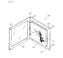
- Fig. 3 is a perspective view of a panel assembly according to the first embodiment of the present invention.
- the panel assembly 200 includes a front panel 210, a front cover 220 pivotably attached at the front of the front panel 210, and an art panel 230 attached at the front of the front panel 210 for mounting a picture or photograph on.
- the front panel 210 has an art panel receiving portion 211 formed at the front thereof for receiving the art panel 230.
- the front cover 220 is supported on a hinge 240 on one edge thereof for pivotably mounting to the front panel 210.
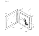
- Fig. 4 is a perspective view of a panel assembly according to the second embodiment of the present invention.
- the panel assembly 200 uses a hook to press the front cover 220 and the front panel 210 together.
- the front cover 220 is pivotably fastened to the panel 210 by a hinge.
- At least one hook 222 is installed at the rear periphery of the front cover 220, so that the front cover 220 presses against the front panel 210 when the front cover 220 is closed.
- a hook receptacle is formed on the front surface of the front panel 210 for inserting the hook 222 therein.
- Fig. 5 is a perspective view of a panel assembly according to the third embodiment of the present invention.
- the panel assembly 200 is characterized by its front cover 220 being completely detachable from its front panel 210.
- a hinge 240 (in Figs. 3 and 4) connecting one side of the front cover 220 to the front panel 210 are hooks and hook receptacles.
- a plurality of hooks 222 are formed on the rear periphery of the front cover 220, and corresponding hook receptacles 212 are formed on the front surface of the front panel 210 for the hooks 222 to be inserted into. Also, an art panel receiving portion 211 formed at the front of the front panel 210 receives an art panel 230. The hook 222 may be formed at the four corners of the front cover 220, so that the front cover 220 may be securely fastened to the front of the front panel 210.
- a user presses the front cover 220 against the front of the front panel 210 so that the hook 222 formed at the rear of the front cover (220) inserts into the hook receptacle 212.
- the front cover 220 is grasped and pulled in a forward direction.
- magnets are installed in place of the hooks 222, so that the front cover 220 can be assembled to the front panel 210 by means of magnetic force.
- a suitable amount of magnetic force may be employed so that a user can easily detach the front cover 220 from the front panel 210.
- the amount of magnetic force may be adjusted so that the front cover 220 does not autonomously disengage from the front panel 210 and fall to the floor.
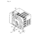
- Fig. 6 is a perspective view of a single unit-type air conditioner having a panel assembly according to the fourth embodiment of the present invention.
- the panel assembly 200 includes a front panel 210 installed to be spaced a predetermined distance from the front of a front frame, a pivoting axis 250 provided on a front surface of the front panel 210, a front cover 220 installed on the pivoting axis 250 to pivot in a clockwise or counter-clockwise direction at the front of the front panel 210, and an art panel received at the front of the front panel 210 and covered by the front cover 220.
- the art panel 230 is protected by the front cover 220 from external shocks and dust. As described above, a picture or photograph is mounted on the front of the art panel 230.
- a latch hook 213 is formed at a front of the front panel 210 opposite the pivoting axis 250 to prevent movement of the front cover 220. Also, a latch receiver 223 is formed at the rear of the front cover 220 for receiving the latch hook 213 inserted therein, to prevent movement of the front cover 220. Conversely, the latch hook 213 may be formed on the front cover 220, and the latch receiver 223 may be formed on the front panel 210.
- a user pivots the front cover 220 in a predetermined arc, so that the latch hook 213 disengages from the latch receiver 223.
- the front cover 220 is returned to its original position by swinging in the reverse direction, so that the latch hook 213 engages and inserts into the latch receiver 223.
- Fig. 7 is perspective view of a panel assembly according to the fifth embodiment of the present invention.
- the panel assembly 200 is characterized in that it includes a cavity formed within the front panel 210 to insert the art panel 230 in, so that the art panel 230 is inserted from the top or from a side of the front panel 210.
- the front panel 210 is made of a transparent material that allows its inside to be visible.
- a cavity made to accommodate the three-dimensional size of the art panel 230 is formed within the front panel 210.
- an art panel insertion slot 214 is formed on the top edge or on a side edge of the front panel 210 to insert the art panel 230 into the cavity.
- the above structure allows easy interchanging of the art panel 230 and also a reduction in manufacturing cost of the panel assembly 200.
- Fig. 8 is a perspective view of a panel assembly according to the sixth embodiment of the present invention.
- the air conditioner 100 includes a front panel 210 installed a predetermined distance to the front of a front frame 110, and a display 300 such as a liquid crystal display (LCD), plasma display panel (PDP), and an organic light emitting diode (OLED) .
- a display 300 such as a liquid crystal display (LCD), plasma display panel (PDP), and an organic light emitting diode (OLED) .
- LCD liquid crystal display
- PDP plasma display panel
- OLED organic light emitting diode
- the front panel 210 or the display 300 has a cable 310 for relaying data provided on a side thereof, so that a digital image signal relayed through the cable 310 can be displayed on the display 300. Accordingly, a user does not need to directly install a picture or photograph, but can save a large quantity of pictures, photographs, or other digital imagery as digital files and selectively display these images on the display 300.
- a user can display them on the display 300 through the cable 310.
- the display 300 By thus providing a digital display on the display 300, there is no need to manually change pictures or photographs, and the front of the air conditioner 100 may function as a monitor as well.
- the indoor portion of the air conditioner according to the present invention performs not only the functions of an indoor portion according to the related art, but also allows the display of easily interchangeable images such as art prints and family portraits at the front thereof, to become a piece of furniture complimenting the interior of a room.
- the structure of the air conditioner indoor portion according to the present invention can augment the interior decoration of a room, and thus has a high industrial applicability.
Landscapes
- Engineering & Computer Science (AREA)
- Chemical & Material Sciences (AREA)
- Combustion & Propulsion (AREA)
- Mechanical Engineering (AREA)
- General Engineering & Computer Science (AREA)
- Air Filters, Heat-Exchange Apparatuses, And Housings Of Air-Conditioning Units (AREA)
- Other Air-Conditioning Systems (AREA)
Applications Claiming Priority (1)
| Application Number | Priority Date | Filing Date | Title |
|---|---|---|---|
| KR1020050019523A KR101054623B1 (ko) | 2005-03-09 | 2005-03-09 | 공기 조화기 |
Publications (2)
| Publication Number | Publication Date |
|---|---|
| EP1707894A1 true EP1707894A1 (fr) | 2006-10-04 |
| EP1707894B1 EP1707894B1 (fr) | 2009-03-11 |
Family
ID=36250795
Family Applications (1)
| Application Number | Title | Priority Date | Filing Date |
|---|---|---|---|
| EP06250434A Expired - Lifetime EP1707894B1 (fr) | 2005-03-09 | 2006-01-26 | Climatiseur |
Country Status (8)
| Country | Link |
|---|---|
| US (1) | US20060201042A1 (fr) |
| EP (1) | EP1707894B1 (fr) |
| KR (1) | KR101054623B1 (fr) |
| CN (2) | CN1831434B (fr) |
| AT (1) | ATE425423T1 (fr) |
| DE (1) | DE602006005532D1 (fr) |
| ES (1) | ES2322666T3 (fr) |
| WO (1) | WO2006095962A1 (fr) |
Cited By (1)
| Publication number | Priority date | Publication date | Assignee | Title |
|---|---|---|---|---|
| EP3165837A4 (fr) * | 2014-07-03 | 2017-06-21 | Qingdao Haier Air Conditioner General Corp., Ltd. | Système de traitement de l'air |
Families Citing this family (10)
| Publication number | Priority date | Publication date | Assignee | Title |
|---|---|---|---|---|
| US20080209934A1 (en) * | 2007-03-01 | 2008-09-04 | Jack Richards | System, method, and apparatus for displaying graphic images on air circulation devices |
| US8752399B2 (en) * | 2009-11-24 | 2014-06-17 | Friedrich Air Conditioning Co., Ltd. | Room air conditioner and/or heater |
| JP5731581B2 (ja) * | 2013-06-25 | 2015-06-10 | 三菱電機株式会社 | 空気調和装置 |
| CN103815705B (zh) * | 2014-03-18 | 2015-09-30 | 周巧 | 便于拆装运输的画框 |
| CN104398073A (zh) * | 2014-11-07 | 2015-03-11 | 苏州博菡环保科技有限公司 | 相框式空气净化器 |
| USD770029S1 (en) * | 2015-01-28 | 2016-10-25 | Magdiel Guillemi | Louver with faceplate |
| CN106123238B (zh) * | 2016-07-18 | 2019-01-15 | 珠海格力电器股份有限公司 | 一种空调的显示方法、装置及空调 |
| US20180031266A1 (en) | 2016-07-27 | 2018-02-01 | Johnson Controls Technology Company | Interactive outdoor display |
| US10876760B2 (en) * | 2017-04-27 | 2020-12-29 | Velma Concetta Paul | Secured mounting frame for an air conditioning unit |
| CN117267805A (zh) * | 2023-08-18 | 2023-12-22 | 海信空调有限公司 | 立式空调器 |
Citations (5)
| Publication number | Priority date | Publication date | Assignee | Title |
|---|---|---|---|---|
| EP1271065A2 (fr) * | 2001-06-19 | 2003-01-02 | Lg Electronics Inc. | Dispositif de conditionnement d'air |
| WO2003014628A2 (fr) * | 2001-08-11 | 2003-02-20 | Lg Electronics Inc. | Conditionneur d'air |
| US20030145618A1 (en) * | 2002-02-07 | 2003-08-07 | Moon Dong Soo | Indoor unit in air conditioner |
| US20040168461A1 (en) * | 2003-01-27 | 2004-09-02 | Park Jung Mee | Unit type air conditioner |
| US20050039480A1 (en) * | 2003-08-18 | 2005-02-24 | Kim Su Hun | Integral type air conditioner |
Family Cites Families (16)
| Publication number | Priority date | Publication date | Assignee | Title |
|---|---|---|---|---|
| US2357697A (en) * | 1942-08-01 | 1944-09-05 | Slater Murray | Jewelry |
| US3160431A (en) * | 1962-02-26 | 1964-12-08 | Nat Lock Co | Latch assembly for medicine cabinets |
| JPH03213921A (ja) * | 1990-01-18 | 1991-09-19 | Mitsubishi Electric Corp | 表示画面付空気調和装置 |
| US5326027A (en) * | 1991-11-12 | 1994-07-05 | American Standard Inc. | Automatic configuration of air conditioning controller |
| IL123390A (en) * | 1997-04-03 | 2000-11-21 | Funai Electric Co | Air conditioning system |
| US5950446A (en) * | 1998-10-01 | 1999-09-14 | Whirlpool Corporation | Compact air conditioner |
| KR100566851B1 (ko) * | 2000-08-28 | 2006-04-03 | 샤프 가부시키가이샤 | 공기 개질 기기 및 이것에 사용되는 이온 발생 장치 |
| KR20020033880A (ko) * | 2000-10-30 | 2002-05-08 | 황한규 | 상치형 에어컨의 전면패널 구조 |
| JP2003322355A (ja) | 2002-04-25 | 2003-11-14 | Matsushita Electric Ind Co Ltd | 空気調和機の室内ユニット |
| KR20040003551A (ko) * | 2002-07-03 | 2004-01-13 | 위니아만도 주식회사 | 멀티미디어장치가 내장된 에어컨 |
| KR200294777Y1 (ko) | 2002-08-09 | 2002-11-16 | 이혜진 | 조명액자가 부착된 벽걸이 에어콘 |
| CN1203281C (zh) * | 2002-11-02 | 2005-05-25 | 海尔集团公司 | 挂壁式空调器室内机 |
| US7249466B2 (en) * | 2003-09-04 | 2007-07-31 | Lg Electronics Inc. | Indoor unit in air conditioner |
| KR100626443B1 (ko) * | 2003-11-24 | 2006-09-20 | 엘지전자 주식회사 | 공기조화기의 실내기 |
| BRPI0418587A (pt) * | 2004-03-04 | 2007-06-26 | Lg Electronics Inc | unidade interna de um ar condicionado |
| BRPI0418649A (pt) * | 2004-04-20 | 2007-05-29 | Lg Electronics Inc | ar condicionado |
-
2005
- 2005-03-09 KR KR1020050019523A patent/KR101054623B1/ko not_active Expired - Fee Related
-
2006
- 2006-01-13 WO PCT/KR2006/000161 patent/WO2006095962A1/fr not_active Ceased
- 2006-01-26 EP EP06250434A patent/EP1707894B1/fr not_active Expired - Lifetime
- 2006-01-26 DE DE602006005532T patent/DE602006005532D1/de not_active Expired - Fee Related
- 2006-01-26 ES ES06250434T patent/ES2322666T3/es not_active Expired - Lifetime
- 2006-01-26 AT AT06250434T patent/ATE425423T1/de not_active IP Right Cessation
- 2006-01-27 US US11/340,718 patent/US20060201042A1/en not_active Abandoned
- 2006-02-21 CN CN2006100086807A patent/CN1831434B/zh not_active Expired - Fee Related
- 2006-02-23 CN CNU2006200031208U patent/CN201021828Y/zh not_active Expired - Fee Related
Patent Citations (5)
| Publication number | Priority date | Publication date | Assignee | Title |
|---|---|---|---|---|
| EP1271065A2 (fr) * | 2001-06-19 | 2003-01-02 | Lg Electronics Inc. | Dispositif de conditionnement d'air |
| WO2003014628A2 (fr) * | 2001-08-11 | 2003-02-20 | Lg Electronics Inc. | Conditionneur d'air |
| US20030145618A1 (en) * | 2002-02-07 | 2003-08-07 | Moon Dong Soo | Indoor unit in air conditioner |
| US20040168461A1 (en) * | 2003-01-27 | 2004-09-02 | Park Jung Mee | Unit type air conditioner |
| US20050039480A1 (en) * | 2003-08-18 | 2005-02-24 | Kim Su Hun | Integral type air conditioner |
Cited By (1)
| Publication number | Priority date | Publication date | Assignee | Title |
|---|---|---|---|---|
| EP3165837A4 (fr) * | 2014-07-03 | 2017-06-21 | Qingdao Haier Air Conditioner General Corp., Ltd. | Système de traitement de l'air |
Also Published As
| Publication number | Publication date |
|---|---|
| DE602006005532D1 (de) | 2009-04-23 |
| KR101054623B1 (ko) | 2011-08-04 |
| EP1707894B1 (fr) | 2009-03-11 |
| ATE425423T1 (de) | 2009-03-15 |
| US20060201042A1 (en) | 2006-09-14 |
| CN1831434A (zh) | 2006-09-13 |
| ES2322666T3 (es) | 2009-06-24 |
| WO2006095962A1 (fr) | 2006-09-14 |
| CN201021828Y (zh) | 2008-02-13 |
| CN1831434B (zh) | 2010-06-16 |
| KR20060098917A (ko) | 2006-09-19 |
Similar Documents
| Publication | Publication Date | Title |
|---|---|---|
| EP1707894B1 (fr) | Climatiseur | |
| EP1701100A2 (fr) | Dispositif de climatisation | |
| US7650709B2 (en) | Air conditioner | |
| EP1703223B1 (fr) | Climatiseur | |
| AU2008200284B2 (en) | Cooling device | |
| EP1696186A1 (fr) | Climatiseur | |
| JP2006194581A (ja) | 空気調和機 | |
| KR20190012841A (ko) | 공기조화기 | |
| KR20020033880A (ko) | 상치형 에어컨의 전면패널 구조 | |
| CN100529556C (zh) | 空调器 | |
| CN223243003U (zh) | 空调器 | |
| CN221403241U (zh) | 立式空调室内机 | |
| CN221403238U (zh) | 立式空调室内机 | |
| CN217559953U (zh) | 空调室内机 | |
| CN200989633Y (zh) | 空调器 | |
| KR200396503Y1 (ko) | 천정용 에어컨 | |
| KR20060098911A (ko) | 공기 조화기 |
Legal Events
| Date | Code | Title | Description |
|---|---|---|---|
| PUAI | Public reference made under article 153(3) epc to a published international application that has entered the european phase |
Free format text: ORIGINAL CODE: 0009012 |
|
| AK | Designated contracting states |
Kind code of ref document: A1 Designated state(s): AT BE BG CH CY CZ DE DK EE ES FI FR GB GR HU IE IS IT LI LT LU LV MC NL PL PT RO SE SI SK TR |
|
| AX | Request for extension of the european patent |
Extension state: AL BA HR MK YU |
|
| 17P | Request for examination filed |
Effective date: 20061106 |
|
| 17Q | First examination report despatched |
Effective date: 20061212 |
|
| AKX | Designation fees paid |
Designated state(s): AT BE BG CH CY CZ DE DK EE ES FI FR GB GR HU IE IS IT LI LT LU LV MC NL PL PT RO SE SI SK TR |
|
| GRAP | Despatch of communication of intention to grant a patent |
Free format text: ORIGINAL CODE: EPIDOSNIGR1 |
|
| GRAS | Grant fee paid |
Free format text: ORIGINAL CODE: EPIDOSNIGR3 |
|
| GRAA | (expected) grant |
Free format text: ORIGINAL CODE: 0009210 |
|
| AK | Designated contracting states |
Kind code of ref document: B1 Designated state(s): AT BE BG CH CY CZ DE DK EE ES FI FR GB GR HU IE IS IT LI LT LU LV MC NL PL PT RO SE SI SK TR |
|
| REG | Reference to a national code |
Ref country code: GB Ref legal event code: FG4D |
|
| REG | Reference to a national code |
Ref country code: CH Ref legal event code: EP |
|
| REG | Reference to a national code |
Ref country code: IE Ref legal event code: FG4D |
|
| REF | Corresponds to: |
Ref document number: 602006005532 Country of ref document: DE Date of ref document: 20090423 Kind code of ref document: P |
|
| REG | Reference to a national code |
Ref country code: ES Ref legal event code: FG2A Ref document number: 2322666 Country of ref document: ES Kind code of ref document: T3 |
|
| PG25 | Lapsed in a contracting state [announced via postgrant information from national office to epo] |
Ref country code: FI Free format text: LAPSE BECAUSE OF FAILURE TO SUBMIT A TRANSLATION OF THE DESCRIPTION OR TO PAY THE FEE WITHIN THE PRESCRIBED TIME-LIMIT Effective date: 20090311 Ref country code: LT Free format text: LAPSE BECAUSE OF FAILURE TO SUBMIT A TRANSLATION OF THE DESCRIPTION OR TO PAY THE FEE WITHIN THE PRESCRIBED TIME-LIMIT Effective date: 20090311 Ref country code: SI Free format text: LAPSE BECAUSE OF FAILURE TO SUBMIT A TRANSLATION OF THE DESCRIPTION OR TO PAY THE FEE WITHIN THE PRESCRIBED TIME-LIMIT Effective date: 20090311 Ref country code: NL Free format text: LAPSE BECAUSE OF FAILURE TO SUBMIT A TRANSLATION OF THE DESCRIPTION OR TO PAY THE FEE WITHIN THE PRESCRIBED TIME-LIMIT Effective date: 20090311 |
|
| NLV1 | Nl: lapsed or annulled due to failure to fulfill the requirements of art. 29p and 29m of the patents act | ||
| PG25 | Lapsed in a contracting state [announced via postgrant information from national office to epo] |
Ref country code: LV Free format text: LAPSE BECAUSE OF FAILURE TO SUBMIT A TRANSLATION OF THE DESCRIPTION OR TO PAY THE FEE WITHIN THE PRESCRIBED TIME-LIMIT Effective date: 20090311 Ref country code: SE Free format text: LAPSE BECAUSE OF FAILURE TO SUBMIT A TRANSLATION OF THE DESCRIPTION OR TO PAY THE FEE WITHIN THE PRESCRIBED TIME-LIMIT Effective date: 20090611 Ref country code: AT Free format text: LAPSE BECAUSE OF FAILURE TO SUBMIT A TRANSLATION OF THE DESCRIPTION OR TO PAY THE FEE WITHIN THE PRESCRIBED TIME-LIMIT Effective date: 20090311 Ref country code: PL Free format text: LAPSE BECAUSE OF FAILURE TO SUBMIT A TRANSLATION OF THE DESCRIPTION OR TO PAY THE FEE WITHIN THE PRESCRIBED TIME-LIMIT Effective date: 20090311 |
|
| PG25 | Lapsed in a contracting state [announced via postgrant information from national office to epo] |
Ref country code: BE Free format text: LAPSE BECAUSE OF FAILURE TO SUBMIT A TRANSLATION OF THE DESCRIPTION OR TO PAY THE FEE WITHIN THE PRESCRIBED TIME-LIMIT Effective date: 20090311 |
|
| PG25 | Lapsed in a contracting state [announced via postgrant information from national office to epo] |
Ref country code: PT Free format text: LAPSE BECAUSE OF FAILURE TO SUBMIT A TRANSLATION OF THE DESCRIPTION OR TO PAY THE FEE WITHIN THE PRESCRIBED TIME-LIMIT Effective date: 20090824 Ref country code: EE Free format text: LAPSE BECAUSE OF FAILURE TO SUBMIT A TRANSLATION OF THE DESCRIPTION OR TO PAY THE FEE WITHIN THE PRESCRIBED TIME-LIMIT Effective date: 20090311 Ref country code: CZ Free format text: LAPSE BECAUSE OF FAILURE TO SUBMIT A TRANSLATION OF THE DESCRIPTION OR TO PAY THE FEE WITHIN THE PRESCRIBED TIME-LIMIT Effective date: 20090311 |
|
| PG25 | Lapsed in a contracting state [announced via postgrant information from national office to epo] |
Ref country code: IS Free format text: LAPSE BECAUSE OF FAILURE TO SUBMIT A TRANSLATION OF THE DESCRIPTION OR TO PAY THE FEE WITHIN THE PRESCRIBED TIME-LIMIT Effective date: 20090711 Ref country code: RO Free format text: LAPSE BECAUSE OF FAILURE TO SUBMIT A TRANSLATION OF THE DESCRIPTION OR TO PAY THE FEE WITHIN THE PRESCRIBED TIME-LIMIT Effective date: 20090311 Ref country code: SK Free format text: LAPSE BECAUSE OF FAILURE TO SUBMIT A TRANSLATION OF THE DESCRIPTION OR TO PAY THE FEE WITHIN THE PRESCRIBED TIME-LIMIT Effective date: 20090311 |
|
| PLBE | No opposition filed within time limit |
Free format text: ORIGINAL CODE: 0009261 |
|
| STAA | Information on the status of an ep patent application or granted ep patent |
Free format text: STATUS: NO OPPOSITION FILED WITHIN TIME LIMIT |
|
| PG25 | Lapsed in a contracting state [announced via postgrant information from national office to epo] |
Ref country code: BG Free format text: LAPSE BECAUSE OF FAILURE TO SUBMIT A TRANSLATION OF THE DESCRIPTION OR TO PAY THE FEE WITHIN THE PRESCRIBED TIME-LIMIT Effective date: 20090611 Ref country code: DK Free format text: LAPSE BECAUSE OF FAILURE TO SUBMIT A TRANSLATION OF THE DESCRIPTION OR TO PAY THE FEE WITHIN THE PRESCRIBED TIME-LIMIT Effective date: 20090311 |
|
| 26N | No opposition filed |
Effective date: 20091214 |
|
| PG25 | Lapsed in a contracting state [announced via postgrant information from national office to epo] |
Ref country code: MC Free format text: LAPSE BECAUSE OF NON-PAYMENT OF DUE FEES Effective date: 20100131 |
|
| REG | Reference to a national code |
Ref country code: CH Ref legal event code: PL |
|
| GBPC | Gb: european patent ceased through non-payment of renewal fee |
Effective date: 20100126 |
|
| REG | Reference to a national code |
Ref country code: IE Ref legal event code: MM4A |
|
| PG25 | Lapsed in a contracting state [announced via postgrant information from national office to epo] |
Ref country code: CH Free format text: LAPSE BECAUSE OF NON-PAYMENT OF DUE FEES Effective date: 20100131 Ref country code: GR Free format text: LAPSE BECAUSE OF FAILURE TO SUBMIT A TRANSLATION OF THE DESCRIPTION OR TO PAY THE FEE WITHIN THE PRESCRIBED TIME-LIMIT Effective date: 20090612 Ref country code: LI Free format text: LAPSE BECAUSE OF NON-PAYMENT OF DUE FEES Effective date: 20100131 |
|
| PG25 | Lapsed in a contracting state [announced via postgrant information from national office to epo] |
Ref country code: DE Free format text: LAPSE BECAUSE OF NON-PAYMENT OF DUE FEES Effective date: 20100803 |
|
| PG25 | Lapsed in a contracting state [announced via postgrant information from national office to epo] |
Ref country code: GB Free format text: LAPSE BECAUSE OF NON-PAYMENT OF DUE FEES Effective date: 20100126 |
|
| PG25 | Lapsed in a contracting state [announced via postgrant information from national office to epo] |
Ref country code: IE Free format text: LAPSE BECAUSE OF NON-PAYMENT OF DUE FEES Effective date: 20100126 |
|
| PGFP | Annual fee paid to national office [announced via postgrant information from national office to epo] |
Ref country code: IT Payment date: 20110122 Year of fee payment: 6 |
|
| PGFP | Annual fee paid to national office [announced via postgrant information from national office to epo] |
Ref country code: ES Payment date: 20110216 Year of fee payment: 6 |
|
| PG25 | Lapsed in a contracting state [announced via postgrant information from national office to epo] |
Ref country code: CY Free format text: LAPSE BECAUSE OF FAILURE TO SUBMIT A TRANSLATION OF THE DESCRIPTION OR TO PAY THE FEE WITHIN THE PRESCRIBED TIME-LIMIT Effective date: 20090311 |
|
| PG25 | Lapsed in a contracting state [announced via postgrant information from national office to epo] |
Ref country code: LU Free format text: LAPSE BECAUSE OF NON-PAYMENT OF DUE FEES Effective date: 20100126 Ref country code: HU Free format text: LAPSE BECAUSE OF FAILURE TO SUBMIT A TRANSLATION OF THE DESCRIPTION OR TO PAY THE FEE WITHIN THE PRESCRIBED TIME-LIMIT Effective date: 20090912 |
|
| PG25 | Lapsed in a contracting state [announced via postgrant information from national office to epo] |
Ref country code: TR Free format text: LAPSE BECAUSE OF FAILURE TO SUBMIT A TRANSLATION OF THE DESCRIPTION OR TO PAY THE FEE WITHIN THE PRESCRIBED TIME-LIMIT Effective date: 20090311 |
|
| PG25 | Lapsed in a contracting state [announced via postgrant information from national office to epo] |
Ref country code: IT Free format text: LAPSE BECAUSE OF NON-PAYMENT OF DUE FEES Effective date: 20120126 |
|
| REG | Reference to a national code |
Ref country code: ES Ref legal event code: FD2A Effective date: 20130708 |
|
| PG25 | Lapsed in a contracting state [announced via postgrant information from national office to epo] |
Ref country code: ES Free format text: LAPSE BECAUSE OF NON-PAYMENT OF DUE FEES Effective date: 20120127 |
|
| PGFP | Annual fee paid to national office [announced via postgrant information from national office to epo] |
Ref country code: FR Payment date: 20131213 Year of fee payment: 9 |
|
| REG | Reference to a national code |
Ref country code: FR Ref legal event code: ST Effective date: 20150930 |
|
| PG25 | Lapsed in a contracting state [announced via postgrant information from national office to epo] |
Ref country code: FR Free format text: LAPSE BECAUSE OF NON-PAYMENT OF DUE FEES Effective date: 20150202 |