EP1707985B1 - Système et procédé de détermination de la position d'un véhicule - Google Patents
Système et procédé de détermination de la position d'un véhicule Download PDFInfo
- Publication number
- EP1707985B1 EP1707985B1 EP06111013A EP06111013A EP1707985B1 EP 1707985 B1 EP1707985 B1 EP 1707985B1 EP 06111013 A EP06111013 A EP 06111013A EP 06111013 A EP06111013 A EP 06111013A EP 1707985 B1 EP1707985 B1 EP 1707985B1
- Authority
- EP
- European Patent Office
- Prior art keywords
- vehicle
- beacon
- curve
- transmission
- position curve
- Prior art date
- Legal status (The legal status is an assumption and is not a legal conclusion. Google has not performed a legal analysis and makes no representation as to the accuracy of the status listed.)
- Ceased
Links
Images






Classifications
-
- G—PHYSICS
- G01—MEASURING; TESTING
- G01S—RADIO DIRECTION-FINDING; RADIO NAVIGATION; DETERMINING DISTANCE OR VELOCITY BY USE OF RADIO WAVES; LOCATING OR PRESENCE-DETECTING BY USE OF THE REFLECTION OR RERADIATION OF RADIO WAVES; ANALOGOUS ARRANGEMENTS USING OTHER WAVES
- G01S13/00—Systems using the reflection or reradiation of radio waves, e.g. radar systems; Analogous systems using reflection or reradiation of waves whose nature or wavelength is irrelevant or unspecified
- G01S13/87—Combinations of radar systems, e.g. primary radar and secondary radar
- G01S13/876—Combination of several spaced transponders or reflectors of known location for determining the position of a receiver
Definitions
- This invention relates to a system and method for determining a position of a vehicle.
- Noise or transient signals may degrade the performance of a system for determining a position of a vehicle.
- the noise may cause inaccuracy in the estimated position of the vehicle.
- US 3 659 085 A describes a system for determining the location of an object.
- a transmitter submits a signal to a number of beacons that submit the point of time of the signal receipt to a central computer.
- the latter calculates the position of the object based on the time of arrival of the signals at the respective beacons.
- US 5 884 215 A describes a system for locating a mobile equipment based upon the time of flight of signals from a transmission station to the equipment or vice versa.
- US 2005/0035897 A1 describes a system and method of locating a target using several receiving elements.
- One of the receiving elements transmits an interrogation signal to a target.
- the return signal from the target is received by a plurality of receiving elements and the target's position is calculated using the time of arrivals of the reply signal and the round trip delay between the transmission of the interrogation signal and the reception of the subsequent reply signal.
- the delay associated with electronic circuitry and processing may vary from one device, module, or transceiver to another. Applying a fixed delay allowance for the electronic circuitry and processing may degrade the performance of the system for determining a position of a vehicle. Accordingly, there is need for providing a variable delay allowance consistent with the variations found between similar devices, modules, or transceivers.
- a method and system for determining the position of a vehicle comprises a transmitter or transceiver for transmitting a transmission signal from a vehicle to beacons associated with the work area. Each beacon is associated with a corresponding transceiver or receiver for receiving the transmission signal.
- a data processor at a beacon, the vehicle or both determines an elapsed time including a first propagation duration and a second propagation duration.
- the first propagation duration refers to a propagation time of the transmission signal from the vehicle to the particular beacon;
- the second propagation duration refers to a propagation time of a return signal from the particular beacon to the vehicle.
- a compensator compensates for the bias delay associated with the transmitter and the particular beacon.
- a data processor processes the elapsed times (for paths between vehicles and beacons) into corresponding position curves or temporal curves to estimate a position of a vehicle at a confluence or intersection of the position curves or temporal curves.
- FIG. 1 shows one embodiment of a system 27 for determining the location or position of a vehicle.
- the system 27 comprises vehicle electronics 16 associated with or mounted on a vehicle.
- the vehicle electronics 16 comprises a mobile transceiver 18 or transmitter that transmits a transmission signal to one or more beacons (91, 92, and 93).
- the beacons comprise a first beacon 91, a second beacon 92, and a third beacon 93 associated with the work area.
- the beacons (91, 92, and 93) may be mounted near or around the perimeter of the work area.
- the beacons comprise transceivers (10, 12, 14).
- the beacons comprise a first transceiver 10, a second transceiver 12, and a third transceiver 14.
- the first transceiver 10 is located at a first site 11; a second transceiver 12 is located at a second site 13; and a third transceiver 14 is located at a third site 15.
- the locations or coordinates of the first site 11, the second site 13, and the third site 15 may be determined during configuration or installation of the system, for example.
- the vehicle electronics 16 comprises a mobile transceiver 18 coupled to a data processor 20.
- the data processor 20 is coupled to a vehicle controller 22.
- the vehicle controller 22 communicates with one or more of the following: a steering system 24, a propulsion system 26, braking system 28, and a path planning module 29.
- the steering system 24 may comprise an electrically controlled hydraulic steering system, an electrically driven rack-and-pinion steering, an Ackerman steering system, or another steering system.
- the braking system 28 may comprise an electrically controlled hydraulic braking system, or another electrically controlled friction braking system.
- the propulsion system 26 may comprise an internal combustion engine, an internal combustion engine-electric hybrid system, an electric drive system, or the like.
- the vehicle controller 22 may generate control signals for the steering system 24, the braking system 28 (if present), and a propulsion system 26 that are consistent with tracking a path plan, provided by the path planning module 29.
- the control signals may comprise a steering control signal or data message that is time dependent and defines a steering angle of the steering shaft; a braking control signal or data message that defines the amount of deceleration, hydraulic pressure, or braking friction applied to brakes; a propulsion control signal or data message that controls a throttle setting, a fuel flow, a fuel injection system, vehicular speed or vehicular acceleration. If the vehicle is propelled by an electric drive or motor, the propulsion control signal or data message may control electrical energy, electrical current, or electrical voltage to the electric drive or motor.
- the system 27 may provide turn-around ranging in which the vehicle electronics 16 or data processor 20 measures elapsed times of propagation for different direct paths between the vehicle electronics 16 and each beacon (91, 92 or 93).
- each elapsed time of propagation represents a temporal difference between a transmission of a transmission signal from the mobile transceiver 18 and the reception time of a return signal at the mobile transceiver 18.
- Each return signal is generated at one of the beacons that receives the transmission signal from the mobile transceiver 18.
- the elapsed time comprises an outgoing path propagation time and an incoming path propagation time between the mobile transceiver 18 and each beacon, among the first beacon 91, the second beacon 92, and the third beacon 93.
- the compensator 82 may compensate for bias delay associated with each beacon.
- the first transceiver 10 may be associated with a first bias delay
- the second transceiver 12 may be associated with a second bias delay
- the third transceiver 14 may be associated with a third bias delay.
- the bias delay results from any signal processing that takes place at the beacon. For example, demodulation of the transmission signal received from the mobile transceiver 18, modulation of the return signal, amplification, coding, or decoding are subject to bias delay.
- the compensator 82 may assign a corresponding bias delay for transmission over a corresponding return signal. Accordingly, the compensator 82 supports distinct bias delays (e.g., first bias delay, second bias delay, and third bias delay) for each beacon to account for differences in the equipment that may occur from variation in components, manufacturing or their environment (e.g., semiconductor fabrication, manufacturing, thermal stress, temperature differences at the site of installation, or otherwise.)
- distinct bias delays e.g., first bias delay, second bias delay, and third bias delay
- the compensator 82 may further comprise a bias compensation device for reducing delay bias, a filter for filtering out phase noise, or both.
- a filter may comprise a phased locked loop circuit for reducing phase noise in a pulse train at baseband or an intermediate frequency associated with a beacon and corresponding propagation path.
- the filter may comprise a lowpass filter prior to a discriminator for identifying a leading edge of the pulses of a pulse train, or another suitable configuration.
- the system 127 of FIG. 2 is similar to the system 27 of FIG. 1 , except the transceivers (110, 112, and 114) of FIG. 2 replace the transceivers (10, 12, and 14) of FIG. 1 .
- the first beacon 191 is associated with the first transceiver 110; the second beacon 192 is associated with the second transceiver 112; the third beacon 193 is associated with the third transceiver 114.
- the first transceiver 110, the second transceiver 112 and the third transceiver 114 each comprise a receiver module (66 or 166 of FIG. 6 of FIG. 7 ) and a transmitter 67.
- the receiver module (66 or 166) comprises an estimator 80 and a compensator 82 as shown later in greater detail.
- the system 127 of FIG. 2 may employ a two-way ranging scheme.
- the mobile transceiver 18 and the other transceiver (110, 112 and/or 114) transmit transmission signals (e.g. identifiable pulses) and receive the transmission signals.
- the transmission signals from the beacon and each site may be transmitted in a simplex manner (e.g., serially) or in a duplex manner (e.g., generally simultaneously) depending upon the modulation scheme or frequency of transmission.
- the transceiver (110, 112 or 114) or vehicle electronics 16 on each side of the communications path between the vehicle and the beacon estimates a time of arrival of the transmission signal.
- errors may be reduced, such as bias delay or transceiver clock errors.
- an errant bias delay for one direction may be reduced in significance by unweighted or weighted averaging with an accurate bias delay in another direction or by applying more sophisticated error detection or correction algorithms.
- the compensator 82 may be located at the vehicle electronics 16 and at each beacon to provide compensation for bias delay, noise measurement error, or both.
- the system 227 of FIG. 3 is similar to the system 127 of FIG. 2 , except the transmitter 167 of FIG. 3 replaces the transmitter 67 of FIG. 2 .
- the first beacon 291 is associated with the first transceiver 210; the second beacon 292 is associated with the second transceiver 212; the third beacon 293 is associated with the third transceiver 214.
- each transmitter 167 comprises a differential data processor 90 and an overhead channel module 92.
- the differential data processor 90 may accept an input of one or more of the following input data: time of arrival data for a transmission signal (e.g., an identifiable pulse), propagation delay data between the vehicle electronics 16 and the beacons (291, 292 and 293), position data, temporal data, or other data indicative of the vehicle location, or precursor thereto.
- the differential data processor 90 outputs differential data based on the input data.
- the differential data represents a change in the input data. For example, if the vehicle is stationary, there may be no differential data or only limited data (e.g., pilot code or tone) to broadcast, because there is no change in position data to convey.
- the differential data processor 90 serves as a data compressor to minimize the bandwidth or transmission capacity among the beacons (291, 292, 293) and the vehicle electronics 16 to facilitate determination of the position (e.g., coordinates) of the vehicle.
- the differential data processor 90 may be well-suited to use in conjunction with an overhead transmission module 92, where bandwidth or the maximum bit rate may be limited.
- the overhead channel module 92 may support transmission of the differential data (or even input data) on a subcarrier or overhead channel (e.g., orthogonal frequency division multiplex (OFDM)).
- a subcarrier or overhead channel e.g., orthogonal frequency division multiplex (OFDM)
- OFDM orthogonal frequency division multiplex
- one example of subcarrier channel is OFDM, which uses overlapping orthogonal signals to divide a frequency selective broadband channel into a group of narrowband channels.
- a block of symbols may be encoded using a Fourier Transform (e.g., Fast Fourier Transform), or another data processing technique and transmitted simultaneously over a number of sub-channels using multiple carriers.
- the mobile transceiver 18 and other transceivers may transmit differential data to one another over a subcarrier channel (e.g., OFDM channel).
- the mobile transceiver 18 may transmit an identifiable pulse (e.g., a pseudo-random noise code, a phase shifting keying modulation, pulse width modulation, pulse amplitude modulation, or another suitable modulation or code) may be transmitted on a carrier (e.g., radio frequency or microwave carrier) or suppressed carrier, whereas a subcarrier channel may be modulated with position data, temporal data, expressed as differential data or otherwise.
- an identifiable pulse e.g., a pseudo-random noise code, a phase shifting keying modulation, pulse width modulation, pulse amplitude modulation, or another suitable modulation or code
- a carrier e.g., radio frequency or microwave carrier
- a subcarrier channel may be modulated with position data, temporal data, expressed as differential data or otherwise.
- the data processor 20 ultimately uses position data or temporal data, or corresponding differential data, for three paths to delay a position solution (e.g., coordinates) for the vehicle: a first propagation path between the vehicle electronics 16 and the first beacon 291, a second propagation path between the vehicle electronics 16 and the second beacon 292, and a third propagation path between the vehicle electronics 16 and the third beacon 293.
- a position solution e.g., coordinates
- each beacon (391, 392, and 393) of FIG. 4 comprises the combination of a receiver (50, 52 and 58) and a communications transceiver (52, 56 and 60), among other things.
- the vehicle electronics 116 of FIG. 4 replaces the mobile transceiver 18 of FIG. 1 with the combination of a mobile transmitter 62 and mobile communications transceiver 64.
- Like reference numbers in FIG. 1 and FIG. 4 indicate like elements.
- the vehicle electronics 116 comprises a mobile transmitter 62 coupled to a mobile communications transceiver 64.
- the mobile communications transceiver 64 communicates with the data processor 20.
- the first beacon 391 comprises a first receiver 50 associated with a first communications transceiver 52.
- the first communications transceiver 52 may comprise a point-to-multipoint transceiver.
- the second beacon 392 comprises the combination of a second receiver 52 and a second communications receiver 56.
- the third beacon 393 comprises a third receiver 58 associated with a third communications receiver 60.
- the system 229 may provide turn-around ranging in which the vehicle electronics 116 or data processor 20 measures elapsed times of propagation for different direct paths between the vehicle electronics 116 and the beacons (391, 392, 393).
- each elapsed time of propagation represents a temporal difference between a transmission of a transmission signal from the mobile transmitter 62 and the reception time of a return signal at the mobile communications transceiver 64.
- Each return signal is generated at one of the beacons (391, 392 or 393) that receives the transmission signal from the vehicle electronics 116.
- the elapsed time comprises an outgoing path propagation time and an incoming path propagation time between the mobile transmitter 62 and each beacon, among the first beacon 391, the second beacon 392, and the third beacon 393.
- the compensator 82 may compensate for bias delay associated with each beacon, phase noise, or other noise, or any combination of bias delay compensation and noise compensation as previously discussed in conjunction with FIG. 1 .
- the system 231 of FIG. 5 is similar to the system 229 of FIG. 4 , except the receivers (150, 154, and 158) of FIG. 5 replace the receivers (50, 52, and 58) of FIG. 4 .
- the receiver module (66 or 166) comprises an estimator 80 and a compensator 82 as shown later in greater detail.
- the system 231 of FIG. 5 may employ a two-way ranging scheme.
- the mobile transmitter 62 and the other communications transceiver(s) (52, 56 and/or 60) transmit transmission signals (e.g. identifiable pulses).
- the receivers (150, 154 and 158) and the mobile communications transceiver 64 receive the transmission signals.
- the first receiver 150, the second receiver 154, and the third receiver 158 at the beacons estimate a time of arrival of the transmission signal.
- the mobile communications transceiver 64 estimates a time of arrival of the return signals transmitted from the first communications transceiver 52, the second communications transceiver 56, and the third communications transceiver 60.
- errors may be reduced, such as bias delay or transceiver clock errors.
- an errant bias delay for one direction (of a propagation path) may be reduced by averaging, weighted averaging, unweighted averaging with a reliable bias delay for an opposite direction (of the propagation path).
- the compensator 82 may be located at the vehicle electronics 116 and at each beacon (491, 492, 493). In one embodiment, the compensator 82 may compensate for bias delay associated with each beacon, phase noise, or any combination of bias delay compensation and noise compensation, as previously discussed in conjunction with FIG. 4 .
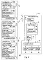
- FIG. 6 provides one possible embodiment for a receiver module 66 consistent with the transceivers of FIG. 2 , FIG. 3 , or FIG. 5 , for example.
- the receiver module 66 comprises an amplifier 68 coupled to a downconverter 70.
- the downconverter 70 is coupled to an analog-to-digital converter 72.
- the analog-to-digital converter 72 is coupled to a data processing system 74.
- the amplifier 68 may comprise a radio-frequency (RF) or microwave pre-amplifier (e.g., a low noise Gallium Arsenide pre-amplifier or receiver front-end).
- the downconverter 70 may comprise a mixer (e.g., a high stability voltage controlled oscillator).
- the data processing system 74 includes a demodulator 78 coupled to an estimator 80.
- the demodulator 78 or estimator 80 may comprise a discriminator for identifying a leading edge of an identifiable pulse of a signal (e.g., a transmission signal or return signal), a discriminator for identifying a trailing edge of a pulse of a signal, or another discriminator for identifying the timing of a pulse.
- the pulse may modulate a carrier signal or a suppressed carrier signal, for example.
- the pulse may be coded in accordance with a pseudo-random noise code (e.g. a PN code) or another modulation or encoding scheme.
- a pseudo-random noise code is typically used with code-division multiple access or spread spectrum systems.
- the estimator 80 is associated with a compensator 82.
- the estimator 80 may provide an input to the converter 84, which is shown in dashed lines to indicate that the converter 84 is optional.
- the estimator 80 estimates the temporal curves representative of propagation delays associated with different propagation paths between the vehicle electronics (16 or 116) and the beacons.
- the description of the compensator 82 previously set forth in the description of FIG. 1 applies equally to FIG. 6 .
- the converter 84 may convert the temporal curves produced by the estimator 80 into distance curves. That is, the converter 84 converts the temporal solution of the estimator 80 into a position solution for the vehicle location (e.g., two or three dimensional coordinates).
- the receiver module 66 may receive a clock signal from a precision clock 88 to assist in synchronization with the transmitter 62 or transceiver 18 that transmits a transmission signal.
- an optional user interface 86 may be coupled to the receiver module 66 to program it.
- the optional user interface 86 may be used to set parameters of the compensator 82, compensator settings, or other data processing settings of the data processing system 74.
- the user interface 86 and the converter 84 is shown in dashed lines to indicate that the user interface 86 and the distance converter are optional elements, and need not be present.
- FIG. 7 shows another embodiment of a receiver module 166.
- the receiver module 166 of FIG. 7 differs from the receiver module 66 of FIG. 6 in that the receiver module 166 of FIG. 7 further includes a detector 94 coupled to a filtering module 96.
- the filtering module 96 and the converter 84 provide input data to a data coordinator 98.
- the detector 94 comprises a Doppler frequency shift detector for detecting a change in frequency of transmission from the vehicle based on the movement, direction or movement, velocity or speed of the vehicle, which may collectively be referred to as velocity data.
- the data coordinator 98 associates, registers, or superimposes the velocity data with the position data output of the converter 84.
- the data coordinator 98 may associate position data (e.g., two or three dimensional coordinates) of the vehicle with corresponding vehicular speed and direction, where available from the detector 94 or the filtering module 96.
- the filtering module 96 discards measured frequency shifts of the detector 94 that exceed a maximum vehicular velocity of the vehicle to reduce data processing requirements (e.g., of the data processor 20 for determination of vehicle position or velocity data).
- the user interface 86 may be used to enter the maximum vehicular velocity data into the filtering module 96.
- FIG. 8 shows a method for determining the location or position of a vehicle in a work area. The method of FIG. 8 begins in step S100.
- a mobile transmitter 62 or mobile transceiver 18 at a vehicle transmits a transmission signal to one or more beacons (e.g., 91, 92, 93) associated with the work area.
- Each beacon is associated with a corresponding transceiver (e.g., 10, 12 14) or receiver for receiving the transmission signal.
- a data processor 20 or data processing system 74 determines an elapsed time for a propagation path between the vehicle and each beacon.
- the elapsed time includes at least one of a first propagation duration and a second propagation duration.
- the first propagation duration refers to an outgoing propagation time of the transmission signal from the vehicle to the particular beacon;
- the second propagation duration refers to an incoming propagation time of a return signal from the particular beacon to the vehicle.
- the elapsed time may represent a round-trip propagation path that is the sum of the first propagation time and the second propagation time.
- the elapsed time may represent one-way propagation path or the average of the first propagation duration and the second propagation duration.
- a compensator 82 compensates for noise or measurement error associated with a corresponding propagation path by invoking at least one of an averaging scheme and a filtering scheme for phase noise reduction.
- the averaging scheme determines the elapsed time for a corresponding propagation duration and second propagation duration based on an average (e.g., mathematical mean) of the first propagation duration and the second propagation duration.
- a compensator 82 or estimator 80 uses a phase locked loop circuit as a filter to filter a pulse or pulse train associated with the receiver module (66 or 166) or decoder to reduce an input noise phase component of the input phase.
- the phase locked loop may comprise a low pass filter to reduce input phase noise at the phase locked loop output relative to the phase locked loop input.
- the phase noise at the output depends upon the loop parameters, such as bandwidth and damping factor.
- the phase locked loop may form a running average over a time duration for the output phase based on its loop bandwidth and a group of pulses.
- the compensator 82 or estimator 80 comprises may comprise a leading edge discriminator.
- the leading edge discriminator detects the arrival time of a pulse to determine the time of receipt of the return signal, for example.
- the leading edge discriminator comprises a phase-locked loop or other precision oscillator for generating a reference signal.
- the reference signal along with a received signal (e.g., associated with an identifiable pulse) is fed to a comparator.
- the noise at the output of the phased lock loop may depend upon loop parameters such as bandwidth and damping factor, which tends to reduce the noise at the output of the comparator.
- a data processor 20 establishes a representation of each elapsed time as a position curve or a temporal curve that indicates a boundary or range of potential positions for the vehicle.
- Each of the elapsed times may be modeled as a temporal curve or a position curve that indicates an estimated position of the vehicle or that indicates boundary within which a vehicle position lies.
- the temporal curves or position curves need not be any particular format, and may be expressed as curve equations, mathematical equations, polynomial expressions, linear equations, vectors, matrices, graphically, or as a series of point coordinates, for example.
- the data processor 20 or converter 84 may derive the position curve from the elapsed times or temporal curves by applying a proportional mathematical relationship between the respective temporal curve and the corresponding position curve for a given propagational path between the vehicle and the beacon.
- a data processor 20 or estimator 80 estimates a position of the vehicle at or near a confluence or intersection of position curves or temporal curves.
- the estimating may be carried out in accordance with various techniques that may be applied alternately or cumulatively.
- the estimator 80 assigns an approximately equal weight to the first position curve, the second position curve, and the third position curve to estimate the position of the vehicle.
- the estimator 80 assigns differential weights to the first position curve, the second position curve, and the third position curve based on at least one probability density function for the first position curve, the second position curve and the third position curve to estimate the position of the vehicle.
- the estimator 80 collects a series of first position curves and averages the series of first position curves over time; the estimator 80 collects a series of second position curves and averaging the series of first position curves over time; and the estimator 80 collects a series of third position curves and averaging the series of position curves over time to estimate the position of the vehicle.
- the estimator 80 collects a series of first position curves and fits the first position curves to a generally linear progression over time
- the estimator 88 collects a series of second position curves and fits the second position curves to a generally linear progression over time
- the estimator 80 collects a series of third position curves and fits the third position curves to a generally linear progression over time in accordance with at least one a least squares approach and a weighted least squares approach.
- the estimator 80 or filter filters by applying differential weights to different position curves to compensate for the influence of noise on the estimated vehicle position.
- the estimator 80 assigns an approximately equal weight to the first temporal curve, the second temporal curve, and the third temporal curve to estimate the position of the vehicle.
- the estimator 80 assigns differential weights to the first temporal curve, the second temporal curve, and the third temporal curve based on at least one probability density function for the first temporal curve, the second temporal curve and the third temporal curve to estimate the position of the vehicle.
- the estimator 80 collects a series of first temporal curves and averages the series of first temporal curves over time; the estimator 80 collects a series of second temporal curves and averaging the series of first temporal curves over time; and the estimator 80 collects a series of third temporal curves and averaging the series of temporal curves over time to estimate the position of the vehicle.
- the estimator 80 collects a series of first temporal curves and fits the first temporal curves to a generally linear progression over time
- the estimator 88 collects a series of second temporal curves and fits the second temporal curves to a generally linear progression over time
- the estimator 80 collects a series of third temporal curves and fits the third temporal curves to a generally linear progression over time in accordance with at least one of a least squares approach and a weighted least squares approach.
- the estimator 80 or filter filters by applying differential weights to different temporal curves to compensate for the influence of noise on the estimated vehicle position.
- FIG. 9 The method of FIG. 9 is similar to the method of FIG. 8 , except step S104 of FIG. 8 is replaced by step S107 of FIG. 9 .
- Like reference numbers in FIG. 8 and FIG. 9 indicate like steps or procedures.
- the estimator 80 or compensator 82 may compensate for bias delay by assigning a custom bias delay (e.g., generally independent or distinct bias delay) associated with each propagation path between the vehicles and beacons.
- a first propagation path may comprise the propagation path between the vehicle and a first beacon; the second propagation path may comprise the propagation path between the vehicle and a second beacon; the third propagation path comprises the propagation path between the vehicle and the third beacon.
- the compensator may assign a first bias delay to the first propagation path, a second bias delay to the second propagation path, and a third bias delay to a third propagation path, where the first bias delay, the second bias delay and the third bias delay may differ independently from one another based on differences in the manufacturing, components, or environment that is associated with each beacon.
- a compensator 82 or estimator 80 applies bias compensation to a turn-around ranging scenario in which a transmission is transmitted from a vehicle to a beacon, and then a return transmission is transmitted from the beacon back to the vehicle.
- the compensator 82 may make a time or distance deduction for bias or processing lag within each beacon.
- the bias compensation deducts a bias delay for one or more of the following: (1) processing of the transmission and generation of the return signal at the beacon, (2) receiving the return signal at the vehicle electronics, and (3) processing of the return signal at the vehicle electronics.
- the bias compensation may depend upon the type of modulation of the transmission, the transmission signal, the return signal, the transmitter hardware, the receiver hardware, and the computational resources of the data processor 20, or data processing system of the receiver module 66 or 166.
- a typical delay factor or a measured (e.g., factory tested) delay factor may be entered into or programmed into data storage, registers, or memory of the compensator 82 or associated devices such that the delay factor may be subtracted from the difference between the transmission time from the vehicle electronics (16 or 116) and the reception time at the vehicle electronics (16 or 116).
- the method of FIG. 9 references a turn-around ranging scenario, the method of FIG. 9 may also be applied generally to two-way ranging or one-way ranging scenarios.
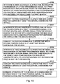
- FIG. 10 shows a method for determining the location or position of a vehicle in a work area.
- the method of FIG. 10 is generally consistent with the bias error reduction aspect of FIG. 9 , except the method of FIG. 10 goes into greater detail with respect to reduction of error associated with bias delay.
- the method of FIG. 10 begins in step S200.
- a first transceiver 10 or first receiver determines a first aggregate elapsed time between the transmission of the first transmission signal to a first beacon 91 and a return signal from the first beacon 91 to the vehicle with compensation for bias delay associated with at least one of the transmitter 67 and the first beacon 91.
- a converter 84 or data processing system converts the first aggregate elapsed time into a first position curve in at least two spatial dimensions for vehicle.
- the first position curve is expressed as differential data to reflect only a change in the first position curve over time to minimize transmission of data associated with the beacons.
- a second transceiver 12 or second receiver determines a second aggregate elapsed time between the transmission of the first transmission signal to a second beacon 92 and receipt of a return signal from the second beacon 92 to the vehicle with compensation for bias delay associated with at least one of the transmitter 67 and the second beacon 92.
- a converter 84 or data processing system converts the second aggregate elapsed time into a second position curve in at least two spatial dimensions for vehicle.
- the second position curve is expressed as differential data to reflect only a change in the second position curve over time to minimize the transmission of data associated with the beacons.
- a third receiver or third transceiver 93 determines a third aggregate elapsed time between the transmission of the first transmission signal to a third beacon 93 and receipt of a return signal from the third beacon 93 to the vehicle with compensation for bias delay associated with at least one of the transmitter 67 and the third beacon 93.
- a converter 84 or data processing system converts the third aggregate elapsed time into a third position curve in at least two spatial dimensions for vehicle.
- the third position curve is expressed as differential data to reflect only a change in the third position over time to minimize the transmission of data associated with the beacons
- step S212 an estimator 80 estimates a position of the vehicle at a confluence or intersection of the first position curve, the second position curve, and the third position curve.
- the estimation of step S212 may be carried out in accordance with various techniques, which may be applied alternately and cumulatively.
- the estimating comprises assigning an approximately equal weight to the first position curve, the second position curve, and the third position curve to estimate the position of the vehicle.
- the estimating comprises assigning differential weights to the first position curve, the second position curve, and the third position curve based on at least one probability density function for the first position curve, the second position curve and the third position curve to estimate the position of the vehicle.
- the estimating comprises collecting a series of first position curves and averaging the series of first position curves over time; collecting a series of second position curves and averaging the series of first position curves over time; and collecting a series of third position curves and averaging the series of position curves over time to estimate the position of the vehicle.
- the estimating comprises collecting a series of first position curves and fitting the first position curves to a generally linear progression over time, collecting a series of second position curves and fitting the second position curves to a generally linear progression over time, collecting a series of third position curves and fitting the third position curves to a generally linear progression over time in accordance with at least one of a least squares approach and a weighted least squares approach.
- FIG. 11 is similar to the method of FIG. 8 , except the method of FIG. 11 replaces step S104 with step S103.
- Like reference numbers in FIG. 8 and FIG. 11 indicate like elements.
- step S103 the compensator 82 compensates for noise or measurement error associated with a corresponding propagation path by invoking a linear fit scheme.
- the linear fit scheme applies a generally linear fit over fixed intervals of noisy measurements of elapsed times, such that the noisy measurements generally conform to a linear portion of a path plan of a vehicle.
- a compensator 82 or estimator 80 applies an averaging or a linear fit over fixed intervals of noisy measurements.
- a linear fit may be applied in accordance with a least squares method or a weighted least squares method. The linear fit is most useful where the vehicle is intended to follow a generally linear spatial path over a time sequence of interest.
- a path planning module 29 may provide a path plan that provides information for the linear fit.
- the least squares estimation may apply calculus equations to estimate the parameter values of a linear model (e.g., a line equation) that minimize the sum of the squared deviations between the observed values (e.g., measurements) and at least a portion of the linear model.
- a linear model e.g., a line equation
- step S103 the method continues with step S106, which has already been described in detail in conjunction with FIG. 8 .
- the method of FIG. 12 may follow the method of FIG. 8 , FIG. 9 , FIG. 10 or FIG. 11 , for example.
- the method of FIG. 12 begins in step S300.
- a detector 94 measures a frequency shift in the first transmission at one or more of the beacons to estimate a vehicular speed or vehicular velocity.
- a Doppler radar detector measures the frequency shift to estimate a vehicular speed or change in direction based on a shift in the frequency transmitted by a mobile transmitter or mobile transceiver of the vehicle electronics 16.
- a data processor 20 or filtering module discards measured frequency shifts at any beacon that exceed a maximum vehicular velocity of the vehicle to reduce data processing requirements of the data processor 20 or the data processing system in the receiver module (66 or 166).
- the maximum vehicular velocity may be imposed by the path planning module 29, physical constraints of the vehicle (e.g., engine horse-power, gear ratios of the drive-train, and tire diameter), or by user preferences entered via the user interface 86.
- the maximum vehicular velocity may be expressed in kilometers per hour, miles per hour, or otherwise.
Landscapes
- Engineering & Computer Science (AREA)
- Radar, Positioning & Navigation (AREA)
- Remote Sensing (AREA)
- Computer Networks & Wireless Communication (AREA)
- Physics & Mathematics (AREA)
- General Physics & Mathematics (AREA)
- Radar Systems Or Details Thereof (AREA)
- Navigation (AREA)
- Position Fixing By Use Of Radio Waves (AREA)
Claims (10)
- Procédé permettant de déterminer la position d'un véhicule, le procédé comprenant les étapes consistant à :transmettre un premier signal de transmission depuis un émetteur (18) sur le véhicule vers au moins trois balises (91, 92, 93, 191, 192, 193, 291, 292, 293, 391, 392, 393, 491, 492, 493) associées à une zone de travail ;transmettre des signaux de retour depuis les balises (91, 92, 93, 191, 192, 193, 291, 292, 293, 391, 392, 393, 491, 492, 493) jusqu'au véhicule ;déterminer un premier temps écoulé total entre la transmission du premier signal de transmission jusqu'à une première balise (91, 191, 291, 391, 491) et d'un signal de retour depuis la première balise (91, 191, 291, 391, 491) jusqu'au véhicule avec compensation d'un retard de polarisation associé à l'émetteur (18) et compensation d'un premier retard de polarisation associé à la première balise (91, 191, 291, 391, 491) ;convertir le premier temps écoulé total en une première courbe de position dans au moins deux dimensions spatiales pour le véhicule ;déterminer un deuxième temps écoulé total entre la transmission du premier signal de transmission à une deuxième balise (92, 192, 292, 392, 492) et d'un signal de retour depuis la deuxième balise (92, 192, 292, 392, 492) jusqu'au véhicule avec compensation d'un retard de polarisation associé à l'émetteur (18) et compensation d'un deuxième retard de polarisation associé à la deuxième balise (92, 192, 292, 392, 492) ;convertir le deuxième temps écoulé total en une deuxième courbe de position dans au moins deux dimensions spatiales pour le véhicule ;déterminer un troisième temps écoulé total entre la transmission du premier signal de transmission à une troisième balise (93, 193, 293, 393, 493) et d'un signal de retour depuis la troisième balise (93, 193, 293, 393, 493) jusqu'au véhicule avec compensation d'un retard de polarisation associé à l'émetteur (18) et compensation d'un troisième retard de polarisation associé à la troisième balise (93, 193, 293, 393, 493) ;convertir le troisième temps écoulé total en une troisième courbe de position dans au moins deux dimensions spatiales pour le véhicule ; etestimer une position du véhicule à un point de confluence ou d'intersection de la première courbe de position, de la deuxième courbe de position et de la troisième courbe de position.
- Procédé selon la revendication 1, l'étape consistant à estimer la position du véhicule comprenant l'étape consistant à attribuer un facteur de pondération sensiblement égal à la première courbe de position, à la deuxième courbe de position et à la troisième courbe de position afin d'estimer la position du véhicule.
- Procédé selon la revendication 1, l'étape consistant à estimer la position du véhicule comprenant l'étape consistant à attribuer des facteurs de pondération différentiels à la première courbe de position, à la deuxième courbe de position et à la troisième courbe de position en fonction d'au moins une fonction de densité de probabilité pour la première courbe de position, la deuxième courbe de position et la troisième courbe de position afin d'estimer la position du véhicule.
- Procédé selon la revendication 1, l'étape consistant à estimer la position du véhicule comprenant les étapes consistant à collecter une série de premières courbes de position et établir la moyenne de la série de premières courbes de position dans le temps ; collecter une série de deuxièmes courbes de position et établir la moyenne de la série de deuxièmes courbes de position dans le temps ; et collecter une série de troisièmes courbes de position et établir la moyenne de la série de troisièmes courbes de position dans le temps afin d'estimer la position du véhicule.
- Procédé selon la revendication 1, l'étape consistant à estimer la position du véhicule comprenant les étapes consistant à collecter une série de premières courbes de position et ajuster les premières courbes de position sur une progression généralement linéaire dans le temps ; collecter une série de deuxièmes courbes de position et ajuster les deuxièmes courbes de position sur une progression généralement linéaire dans le temps ; collecter une série de troisièmes courbes de position et ajuster les troisièmes courbes de position sur une progression généralement linéaire dans le temps selon une méthode des moindres carrés et/ou une méthode des moindres carrés pondérés.
- Procédé selon la revendication 1, la première courbe de position étant exprimée par des données différentielles pour indiquer uniquement une variation de la première courbe de position dans le temps afin de minimiser la transmission de données associée aux balises (91, 92, 93, 191, 192, 193, 291, 292, 293, 391, 392, 393, 491, 492, 493) ; la deuxième courbe de position étant exprimée par des données différentielles pour indiquer uniquement une variation de la deuxième courbe de position dans le temps afin de minimiser la transmission de données associée aux balises (91, 92, 93, 191, 192, 193, 291, 292, 293, 391, 392, 393, 491, 492, 493) ; la troisième courbe de position étant exprimée par des données différentielles pour indiquer uniquement une variation de la troisième courbe de position dans le temps afin de minimiser la transmission de données associée aux balises (91, 92, 93, 191, 192, 193, 291, 292, 293, 391, 392, 393, 491, 492, 493).
- Procédé selon la revendication 1, les données différentielles étant transmises depuis une balise (91, 92, 93, 191, 192, 193, 291, 292, 293, 391, 392, 393, 491, 492, 493) jusqu'à une autre ou entre une balise (91, 92, 93, 191, 192, 193, 291, 292, 293, 391, 392, 393, 491, 492, 493) et le véhicule sur une voie de sous-porteuse associée aux balises (91, 92, 93, 191, 192, 193, 291, 292, 293, 391, 392, 393, 491, 492, 493).
- Procédé selon la revendication 1, les données différentielles comprenant une sortie d'un système de télémétrie radiofréquence.
- Procédé selon la revendication 1, comprenant en outre les étapes consistant à :mesurer un déplacement de fréquence dans le premier signal de transmission au niveau d'au moins une des balises afin d'estimer une vitesse scalaire du véhicule ou une vitesse vectorielle du véhicule ; etignorer les déplacements de fréquence mesurés au niveau d'une quelconque balise (91, 92, 93, 191, 192, 193, 291, 292, 293, 391, 392, 393, 491, 492, 493) qui excèdent une vitesse vectorielle maximale du véhicule afin de réduire les besoins en traitement de données.
- Système (27, 127, 227, 229, 231) permettant de déterminer la position d'un véhicule, le système comprenant :un premier émetteur (62) servant à transmettre un premier signal de transmission depuis l'émetteur (62) sur le véhicule vers au moins une balise (91, 92, 93, 191, 192, 193, 291, 292, 293, 391, 392, 393, 491, 492, 493) associée à une zone de travail ;un émetteur-récepteur mobile (64) sur le véhicule servant à recevoir un signal de retour depuis la balise particulière (91, 92, 93, 191, 192, 193, 291, 292, 293, 391, 392, 393, 491, 492, 493) jusqu'au véhicule ;un estimateur de temps (80) servant à déterminer un premier temps écoulé total entre la transmission du premier signal de transmission jusqu'à une première balise (91, 191, 291, 391, 491) et d'un signal de retour depuis la première balise (91, 191, 291, 391, 491) jusqu'au véhicule, un deuxième temps écoulé total entre la transmission du premier signal de transmission à une deuxième balise (92, 192, 292, 392, 492) et d'un signal de retour depuis la deuxième balise (92, 192, 292, 392, 492) jusqu'au véhicule et un troisième temps écoulé total entre la transmission du premier signal de transmission à une troisième balise (93, 193, 293, 393, 493) et d'un signal de retour depuis la troisième balise (93, 193, 293, 393, 493) jusqu'au véhicule ;un compensateur de polarisation (82) servant à compenser un retard de polarisation associé à l'émetteur (62), un premier retard de polarisation associé à la première balise (91, 191, 291, 391, 491), un deuxième retard de polarisation associé à la deuxième balise (92, 192, 292, 392, 492) et un troisième retard de polarisation associé à la troisième balise (93, 193, 293, 393, 493) ;un convertisseur (84) servant à convertir le premier temps écoulé total en une première courbe de position dans au moins deux dimensions spatiales pour le véhicule, le deuxième temps écoulé total en une deuxième courbe de position dans au moins deux dimensions spatiales pour le véhicule et le troisième temps écoulé total en une troisième courbe de position dans au moins deux dimensions spatiales pour le véhicule ; etun processeur de données servant à estimer une position du véhicule à un point de confluence ou d'intersection de la première courbe de position, de la deuxième courbe de position et de la troisième courbe de position.
Applications Claiming Priority (2)
| Application Number | Priority Date | Filing Date | Title |
|---|---|---|---|
| US66715405P | 2005-03-31 | 2005-03-31 | |
| US11/208,337 US7647177B2 (en) | 2005-03-31 | 2005-08-19 | System and method for determining a position of a vehicle |
Publications (3)
| Publication Number | Publication Date |
|---|---|
| EP1707985A2 EP1707985A2 (fr) | 2006-10-04 |
| EP1707985A3 EP1707985A3 (fr) | 2010-09-29 |
| EP1707985B1 true EP1707985B1 (fr) | 2012-06-13 |
Family
ID=36657867
Family Applications (1)
| Application Number | Title | Priority Date | Filing Date |
|---|---|---|---|
| EP06111013A Ceased EP1707985B1 (fr) | 2005-03-31 | 2006-03-13 | Système et procédé de détermination de la position d'un véhicule |
Country Status (2)
| Country | Link |
|---|---|
| US (1) | US7647177B2 (fr) |
| EP (1) | EP1707985B1 (fr) |
Families Citing this family (10)
| Publication number | Priority date | Publication date | Assignee | Title |
|---|---|---|---|---|
| US7653483B2 (en) * | 2005-03-31 | 2010-01-26 | Deere & Company | System and method for determining a position of a vehicle |
| US7593811B2 (en) * | 2005-03-31 | 2009-09-22 | Deere & Company | Method and system for following a lead vehicle |
| US7479922B2 (en) * | 2005-03-31 | 2009-01-20 | Deere & Company | Method and system for determining the location of a vehicle |
| AU2015200274B2 (en) * | 2008-07-04 | 2016-12-01 | Caterpillar Inc. | Wireless localisation system |
| EP2307902B1 (fr) * | 2008-07-04 | 2013-09-25 | Commonwealth Scientific and Industrial Research Organisation | Système de localisation sans fil |
| US8040135B1 (en) * | 2010-05-27 | 2011-10-18 | The Board Of Trustees Of The Leland Stanford Junior University | Contrast and resolution enhancement with signal compensation |
| JP6054638B2 (ja) * | 2012-05-30 | 2016-12-27 | クラリオン株式会社 | 車両位置検出装置およびプログラム |
| WO2019068175A1 (fr) * | 2017-10-03 | 2019-04-11 | Xco Tech Inc. | Système et procédé de détermination de position |
| US12016257B2 (en) | 2020-02-19 | 2024-06-25 | Sabanto, Inc. | Methods for detecting and clearing debris from planter gauge wheels, closing wheels and seed tubes |
| US12461083B2 (en) | 2020-08-03 | 2025-11-04 | Sabanto, Inc. | Methods for improved agricultural procedures |
Citations (1)
| Publication number | Priority date | Publication date | Assignee | Title |
|---|---|---|---|---|
| US20050035897A1 (en) * | 2003-08-14 | 2005-02-17 | Sensis Corporation | Target localization using TDOA distributed antenna |
Family Cites Families (70)
| Publication number | Priority date | Publication date | Assignee | Title |
|---|---|---|---|---|
| US2008220A (en) * | 1934-09-14 | 1935-07-16 | Miyeno Yukichi | Bill fold and purse |
| US3659085A (en) | 1970-04-30 | 1972-04-25 | Sierra Research Corp | Computer determining the location of objects in a coordinate system |
| US4883480A (en) * | 1984-08-17 | 1989-11-28 | Mcneil-Ppc, Inc. | Infant diaper with improved fit |
| US4706120A (en) | 1985-08-30 | 1987-11-10 | Texas Instruments Incorporated | Modular, vision system for automation of inspection and process control |
| CA1271546A (fr) | 1985-10-08 | 1990-07-10 | Accutrak Systems Limited | Systeme de guidage de vehicule et de telemetrie |
| US4829442A (en) | 1986-05-16 | 1989-05-09 | Denning Mobile Robotics, Inc. | Beacon navigation system and method for guiding a vehicle |
| US4710020A (en) | 1986-05-16 | 1987-12-01 | Denning Mobil Robotics, Inc. | Beacon proximity detection system for a vehicle |
| FR2610400B1 (fr) | 1987-02-04 | 1989-04-28 | Paramythioti Michel | Procede et dispositif de relevement tridimensionnel |
| FI900645A0 (fi) | 1987-08-10 | 1990-02-09 | Duffett Smith Peter James | Navigerings- och uppspaoringssystem. |
| US5657317A (en) | 1990-01-18 | 1997-08-12 | Norand Corporation | Hierarchical communication system using premises, peripheral and vehicular local area networking |
| US5610815A (en) | 1989-12-11 | 1997-03-11 | Caterpillar Inc. | Integrated vehicle positioning and navigation system, apparatus and method |
| US5390125A (en) | 1990-02-05 | 1995-02-14 | Caterpillar Inc. | Vehicle position determination system and method |
| US5646843A (en) | 1990-02-05 | 1997-07-08 | Caterpillar Inc. | Apparatus and method for surface based vehicle control system |
| US5307271A (en) | 1990-09-28 | 1994-04-26 | The United States Of America As Represented By The Secretary Of The Navy | Reflexive teleoperated control system for a remotely controlled vehicle |
| DE4211933A1 (de) | 1992-04-09 | 1993-10-14 | Philips Patentverwaltung | Anordnung zur Positionsbestimmung eines Landfahrzeugs |
| US5491670A (en) * | 1993-01-21 | 1996-02-13 | Weber; T. Jerome | System and method for sonic positioning |
| US5491476A (en) | 1993-10-01 | 1996-02-13 | Dibella; James A. | Magnetically triggered elapsed time indicator |
| SE514791C2 (sv) | 1994-06-06 | 2001-04-23 | Electrolux Ab | Förbättrat förfarande för lokalisering av fyrar vid självgående anordning |
| JP3628046B2 (ja) | 1994-08-31 | 2005-03-09 | 株式会社デンソー | 車両用現在位置検出装置 |
| DE19509320A1 (de) | 1995-03-15 | 1996-09-19 | Technologietransfer Anstalt Te | Folgesteuerung für ein selbstfahrendes Fahrzeug |
| IL113913A (en) | 1995-05-30 | 2000-02-29 | Friendly Machines Ltd | Navigation method and system |
| US7110880B2 (en) | 1997-10-22 | 2006-09-19 | Intelligent Technologies International, Inc. | Communication method and arrangement |
| US5933079A (en) | 1995-09-01 | 1999-08-03 | Remote Data Systems, Inc. | Signal discriminator and positioning system |
| US6057800A (en) | 1996-06-28 | 2000-05-02 | State University Of New York | RDOP surface for GPS relative positioning |
| US5681670A (en) | 1996-07-26 | 1997-10-28 | Mitsubishi Chemical Corporation | Electrode support in a multilayer cell |
| US6107959A (en) | 1996-09-30 | 2000-08-22 | Qualcomm Incorporated | Positioning determination using one low-Earth orbit satellite |
| US6327534B1 (en) | 1996-09-30 | 2001-12-04 | Qualcomm Incorporated | Unambiguous position determination using two low-earth orbit satellites |
| US5874918A (en) | 1996-10-07 | 1999-02-23 | Lockheed Martin Corporation | Doppler triangulation transmitter location system |
| US5940346A (en) * | 1996-12-13 | 1999-08-17 | Arizona Board Of Regents | Modular robotic platform with acoustic navigation system |
| US5884215A (en) | 1997-01-31 | 1999-03-16 | Motorola, Inc. | Method and apparatus for covariance matrix estimation in a weighted least-squares location solution |
| US5974347A (en) | 1997-03-14 | 1999-10-26 | Nelson; Russell G. | Automated lawn mower |
| JP3366220B2 (ja) | 1997-05-26 | 2003-01-14 | 本田技研工業株式会社 | 道路形状判定装置及び車両制御装置 |
| US6011974A (en) | 1997-09-23 | 2000-01-04 | Telefonaktiebolaget L M Ericsson (Publ) | Method and system for determining position of a cellular mobile terminal |
| US5986602A (en) | 1998-03-02 | 1999-11-16 | Remote Data Systems, Inc. | Pulse radar device and method |
| US6072421A (en) | 1998-05-29 | 2000-06-06 | Mitsubishi Denki Kabushiki Kaisha | Moving object high-accuracy position locating method and system |
| US6313786B1 (en) | 1998-07-02 | 2001-11-06 | Snaptrack, Inc. | Method and apparatus for measurement processing of satellite positioning system (SPS) signals |
| US6212448B1 (en) | 1998-11-13 | 2001-04-03 | Paul G. Angott | RF only guidance system |
| US6125135A (en) | 1998-11-25 | 2000-09-26 | Navcom Technology, Inc. | System and method for demodulating global positioning system signals |
| US6369754B1 (en) | 1999-04-02 | 2002-04-09 | Qualcomm Inc. | Fine positioning of a user terminal in a satellite communication system |
| US6560536B1 (en) | 1999-07-12 | 2003-05-06 | Eagle-Eye, Inc. | System and method for rapid telepositioning |
| US6427079B1 (en) | 1999-08-09 | 2002-07-30 | Cormedica Corporation | Position and orientation measuring with magnetic fields |
| US6760663B2 (en) | 1999-09-14 | 2004-07-06 | Honeywell International Inc. | Solution separation method and apparatus for ground-augmented global positioning system |
| US7411921B2 (en) | 1999-10-21 | 2008-08-12 | Rf Technologies, Inc. | Method and apparatus for integrating wireless communication and asset location |
| US6420862B2 (en) | 2000-02-14 | 2002-07-16 | The United States Of America As Represented By The Administrator Of The National Aeronautics And Space Administration | System and method of locating lightning strikes |
| JP3421768B2 (ja) | 2000-03-30 | 2003-06-30 | 学校法人金沢工業大学 | 自律移動車の進路誘導方法ならびに自律移動車の進路誘導装置および進路誘導装置を備えた自律移動車 |
| JP3740953B2 (ja) | 2000-06-13 | 2006-02-01 | 株式会社日立製作所 | 無線位置測定端末および無線位置測定システム |
| US6407703B1 (en) | 2000-08-07 | 2002-06-18 | Lockheed Martin Corporation | Multi-platform geolocation method and system |
| US6556942B1 (en) | 2000-09-29 | 2003-04-29 | Ut-Battelle, Llc | Short range spread-spectrum radiolocation system and method |
| US6424264B1 (en) | 2000-10-12 | 2002-07-23 | Safetzone Technologies Corporation | System for real-time location of people in a fixed environment |
| US6614721B2 (en) | 2000-10-13 | 2003-09-02 | Edward Bokhour | Collision avoidance method and system |
| US6420999B1 (en) | 2000-10-26 | 2002-07-16 | Qualcomm, Inc. | Method and apparatus for determining an error estimate in a hybrid position determination system |
| US6489917B2 (en) | 2000-11-30 | 2002-12-03 | Georgia Tech Research Corporation | Phase-based sensing system |
| US6525688B2 (en) | 2000-12-04 | 2003-02-25 | Enuvis, Inc. | Location-determination method and apparatus |
| JP2002320254A (ja) | 2001-04-20 | 2002-10-31 | Pioneer Electronic Corp | 移動体通信装置及びその位置検出方法 |
| US7266532B2 (en) | 2001-06-01 | 2007-09-04 | The General Hospital Corporation | Reconfigurable autonomous device networks |
| CN100451195C (zh) | 2001-12-19 | 2009-01-14 | 特鲁菲舍尔股份有限公司及两合公司 | 测定前端扭曲的调整值的装置 |
| US6674687B2 (en) | 2002-01-25 | 2004-01-06 | Navcom Technology, Inc. | System and method for navigation using two-way ultrasonic positioning |
| DE10224939B4 (de) | 2002-05-31 | 2009-01-08 | Deere & Company, Moline | Triebachs-Anhänger |
| US6963301B2 (en) | 2002-08-19 | 2005-11-08 | G-Track Corporation | System and method for near-field electromagnetic ranging |
| US7660588B2 (en) | 2002-10-17 | 2010-02-09 | Qualcomm Incorporated | Method and apparatus for improving radio location accuracy with measurements |
| US20040243134A1 (en) * | 2003-05-30 | 2004-12-02 | Walker Peter Stanley | Bone shaping device for knee replacement |
| US7286624B2 (en) | 2003-07-03 | 2007-10-23 | Navcom Technology Inc. | Two-way RF ranging system and method for local positioning |
| JP3897740B2 (ja) | 2003-07-23 | 2007-03-28 | トヨタ自動車株式会社 | 車両の自動誘導装置及び車両位置推定装置 |
| US7751829B2 (en) | 2003-09-22 | 2010-07-06 | Fujitsu Limited | Method and apparatus for location determination using mini-beacons |
| GB0325622D0 (en) | 2003-11-03 | 2003-12-10 | Cambridge Consultants | System for determining positional information |
| US6861979B1 (en) | 2004-01-16 | 2005-03-01 | Topcon Gps, Llc | Method and apparatus for detecting anomalous measurements in a satellite navigation receiver |
| US20060014548A1 (en) | 2004-07-16 | 2006-01-19 | Telefonaktiebolaget Lm Ericsson (Publ) | Determination of mobile terminal position |
| US7826343B2 (en) | 2004-09-07 | 2010-11-02 | Qualcomm Incorporated | Position location signaling method apparatus and system utilizing orthogonal frequency division multiplexing |
| US7349746B2 (en) | 2004-09-10 | 2008-03-25 | Exxonmobil Research And Engineering Company | System and method for abnormal event detection in the operation of continuous industrial processes |
| US7026992B1 (en) | 2005-03-31 | 2006-04-11 | Deere & Company | Method for configuring a local positioning system |
-
2005
- 2005-08-19 US US11/208,337 patent/US7647177B2/en active Active
-
2006
- 2006-03-13 EP EP06111013A patent/EP1707985B1/fr not_active Ceased
Patent Citations (1)
| Publication number | Priority date | Publication date | Assignee | Title |
|---|---|---|---|---|
| US20050035897A1 (en) * | 2003-08-14 | 2005-02-17 | Sensis Corporation | Target localization using TDOA distributed antenna |
Also Published As
| Publication number | Publication date |
|---|---|
| EP1707985A2 (fr) | 2006-10-04 |
| US7647177B2 (en) | 2010-01-12 |
| EP1707985A3 (fr) | 2010-09-29 |
| US20060224308A1 (en) | 2006-10-05 |
Similar Documents
| Publication | Publication Date | Title |
|---|---|---|
| EP1707984B1 (fr) | Système et procédé de détermination de la position d'un véhicule | |
| EP1707986B1 (fr) | Système et procédé de détermination de la position d'un véhicule | |
| EP1707980B1 (fr) | Procédé de configuration d'un système de positionnement local | |
| US10317525B2 (en) | Robust dual-radar-beam systems and methods for traffic monitoring | |
| US8041469B2 (en) | Determining relative spatial information between vehicles | |
| EP0940691A2 (fr) | Procédé et appareil de détection de distance | |
| EP1707985B1 (fr) | Système et procédé de détermination de la position d'un véhicule | |
| WO2013140747A1 (fr) | Dispositif de radar | |
| US20120095673A1 (en) | Apparatus and method for providing driving information for vehicles based on high speed movement long distance impuse radio ultra wideband | |
| Ge et al. | V2X sidelink positioning in FR1: Scenarios, algorithms, and performance evaluation | |
| Park et al. | Optimal pilot and data power allocation for joint communication-radar air-to-ground networks | |
| Liu et al. | Joint localization and predictive beamforming in vehicular networks: Power allocation beyond water-filling | |
| US12306335B2 (en) | Method for determining at least one piece of object information about at least one object sensed by means of a radar system and radar system | |
| Lübke et al. | Combining radar and communication at 77 GHz using a CDMA technique | |
| CN113075615B (zh) | 确定运输工具的位置和/或取向的设备和方法以及固定站 | |
| EP2504936B1 (fr) | Extraction de paramètres d'un canal de communication | |
| US20070249400A1 (en) | Base Station and Mobile Station in Mobile Communication System and Direction Detecting Method | |
| KR101591063B1 (ko) | 레이더 장치 | |
| CN120548757A (zh) | 无线通信系统中发送/接收无线信号的方法和设备 | |
| Tamer | Relative localization of wireless sensor nodes by using the RSSI and TOA based distance estimations | |
| US20250044462A1 (en) | Doppler based cellular navigation system | |
| Mizui et al. | Vehicle‐to‐vehicle communications and ranging system using spread spectrum techniques | |
| Schaffer et al. | A 5.8 GHz Cooperative Transponder System for Localization and Communication in Traffic Safety Applications | |
| Nagaraj | Frequency Based Ranging (FBR) for Bluetooth Channel Sounding on a Single 2 MHz Channel | |
| Hataki et al. | Improving Data Rate Using Cyclic Shifts in an FMCW Radar System Combining Ranging and Communication |
Legal Events
| Date | Code | Title | Description |
|---|---|---|---|
| PUAI | Public reference made under article 153(3) epc to a published international application that has entered the european phase |
Free format text: ORIGINAL CODE: 0009012 |
|
| AK | Designated contracting states |
Kind code of ref document: A2 Designated state(s): AT BE BG CH CY CZ DE DK EE ES FI FR GB GR HU IE IS IT LI LT LU LV MC NL PL PT RO SE SI SK TR |
|
| AX | Request for extension of the european patent |
Extension state: AL BA HR MK YU |
|
| PUAL | Search report despatched |
Free format text: ORIGINAL CODE: 0009013 |
|
| AK | Designated contracting states |
Kind code of ref document: A3 Designated state(s): AT BE BG CH CY CZ DE DK EE ES FI FR GB GR HU IE IS IT LI LT LU LV MC NL PL PT RO SE SI SK TR |
|
| AX | Request for extension of the european patent |
Extension state: AL BA HR MK YU |
|
| RIC1 | Information provided on ipc code assigned before grant |
Ipc: G01S 13/87 20060101AFI20060721BHEP Ipc: G01S 5/06 20060101ALI20100823BHEP |
|
| 17P | Request for examination filed |
Effective date: 20110329 |
|
| AKX | Designation fees paid |
Designated state(s): DE GB |
|
| 17Q | First examination report despatched |
Effective date: 20110616 |
|
| GRAP | Despatch of communication of intention to grant a patent |
Free format text: ORIGINAL CODE: EPIDOSNIGR1 |
|
| GRAS | Grant fee paid |
Free format text: ORIGINAL CODE: EPIDOSNIGR3 |
|
| GRAA | (expected) grant |
Free format text: ORIGINAL CODE: 0009210 |
|
| AK | Designated contracting states |
Kind code of ref document: B1 Designated state(s): DE GB |
|
| REG | Reference to a national code |
Ref country code: GB Ref legal event code: FG4D |
|
| REG | Reference to a national code |
Ref country code: DE Ref legal event code: R096 Ref document number: 602006030070 Country of ref document: DE Effective date: 20120809 |
|
| PLBE | No opposition filed within time limit |
Free format text: ORIGINAL CODE: 0009261 |
|
| STAA | Information on the status of an ep patent application or granted ep patent |
Free format text: STATUS: NO OPPOSITION FILED WITHIN TIME LIMIT |
|
| 26N | No opposition filed |
Effective date: 20130314 |
|
| REG | Reference to a national code |
Ref country code: DE Ref legal event code: R097 Ref document number: 602006030070 Country of ref document: DE Effective date: 20130314 |
|
| PGFP | Annual fee paid to national office [announced via postgrant information from national office to epo] |
Ref country code: DE Payment date: 20240221 Year of fee payment: 19 Ref country code: GB Payment date: 20240327 Year of fee payment: 19 |
|
| REG | Reference to a national code |
Ref country code: DE Ref legal event code: R119 Ref document number: 602006030070 Country of ref document: DE |
|
| GBPC | Gb: european patent ceased through non-payment of renewal fee |
Effective date: 20250313 |
|
| PG25 | Lapsed in a contracting state [announced via postgrant information from national office to epo] |
Ref country code: DE Free format text: LAPSE BECAUSE OF NON-PAYMENT OF DUE FEES Effective date: 20251001 |
|
| PG25 | Lapsed in a contracting state [announced via postgrant information from national office to epo] |
Ref country code: GB Free format text: LAPSE BECAUSE OF NON-PAYMENT OF DUE FEES Effective date: 20250313 |