EP1708009A2 - Système optique de projection d'une ligne d'illumination, à partir d'un réseau de lasers - Google Patents
Système optique de projection d'une ligne d'illumination, à partir d'un réseau de lasers Download PDFInfo
- Publication number
- EP1708009A2 EP1708009A2 EP06112177A EP06112177A EP1708009A2 EP 1708009 A2 EP1708009 A2 EP 1708009A2 EP 06112177 A EP06112177 A EP 06112177A EP 06112177 A EP06112177 A EP 06112177A EP 1708009 A2 EP1708009 A2 EP 1708009A2
- Authority
- EP
- European Patent Office
- Prior art keywords
- optical system
- illumination
- anamorphic lens
- lens structure
- laser diodes
- Prior art date
- Legal status (The legal status is an assumption and is not a legal conclusion. Google has not performed a legal analysis and makes no representation as to the accuracy of the status listed.)
- Withdrawn
Links
Images


Classifications
-
- G—PHYSICS
- G02—OPTICS
- G02B—OPTICAL ELEMENTS, SYSTEMS OR APPARATUS
- G02B19/00—Condensers, e.g. light collectors or similar non-imaging optics
- G02B19/0033—Condensers, e.g. light collectors or similar non-imaging optics characterised by the use
- G02B19/0047—Condensers, e.g. light collectors or similar non-imaging optics characterised by the use for use with a light source
- G02B19/0052—Condensers, e.g. light collectors or similar non-imaging optics characterised by the use for use with a light source the light source comprising a laser diode
- G02B19/0057—Condensers, e.g. light collectors or similar non-imaging optics characterised by the use for use with a light source the light source comprising a laser diode in the form of a laser diode array, e.g. laser diode bar
-
- G—PHYSICS
- G02—OPTICS
- G02B—OPTICAL ELEMENTS, SYSTEMS OR APPARATUS
- G02B19/00—Condensers, e.g. light collectors or similar non-imaging optics
- G02B19/0004—Condensers, e.g. light collectors or similar non-imaging optics characterised by the optical means employed
- G02B19/0009—Condensers, e.g. light collectors or similar non-imaging optics characterised by the optical means employed having refractive surfaces only
- G02B19/0014—Condensers, e.g. light collectors or similar non-imaging optics characterised by the optical means employed having refractive surfaces only at least one surface having optical power
-
- G—PHYSICS
- G02—OPTICS
- G02B—OPTICAL ELEMENTS, SYSTEMS OR APPARATUS
- G02B27/00—Optical systems or apparatus not provided for by any of the groups G02B1/00 - G02B26/00, G02B30/00
- G02B27/09—Beam shaping, e.g. changing the cross-sectional area, not otherwise provided for
- G02B27/0905—Dividing and/or superposing multiple light beams
-
- G—PHYSICS
- G02—OPTICS
- G02B—OPTICAL ELEMENTS, SYSTEMS OR APPARATUS
- G02B27/00—Optical systems or apparatus not provided for by any of the groups G02B1/00 - G02B26/00, G02B30/00
- G02B27/09—Beam shaping, e.g. changing the cross-sectional area, not otherwise provided for
- G02B27/0911—Anamorphotic systems
-
- G—PHYSICS
- G02—OPTICS
- G02B—OPTICAL ELEMENTS, SYSTEMS OR APPARATUS
- G02B27/00—Optical systems or apparatus not provided for by any of the groups G02B1/00 - G02B26/00, G02B30/00
- G02B27/09—Beam shaping, e.g. changing the cross-sectional area, not otherwise provided for
- G02B27/0938—Using specific optical elements
- G02B27/095—Refractive optical elements
- G02B27/0955—Lenses
- G02B27/0966—Cylindrical lenses
-
- G—PHYSICS
- G02—OPTICS
- G02B—OPTICAL ELEMENTS, SYSTEMS OR APPARATUS
- G02B27/00—Optical systems or apparatus not provided for by any of the groups G02B1/00 - G02B26/00, G02B30/00
- G02B27/28—Optical systems or apparatus not provided for by any of the groups G02B1/00 - G02B26/00, G02B30/00 for polarising
- G02B27/286—Optical systems or apparatus not provided for by any of the groups G02B1/00 - G02B26/00, G02B30/00 for polarising for controlling or changing the state of polarisation, e.g. transforming one polarisation state into another
Definitions
- the invention generally relates to imaging systems, and relates in particular to imaging systems that employ a line of laser illumination.
- FA fast axis
- U.S. Patent No. 6,494,371 discloses a diode-laser light projector for illuminating a linear array of light modulators.
- the system is arranged to focus fast axis diverging rays of the diode-lasers in a focal plane perpendicular to the longitudinal axis, and arranged to form the slow axis diverging rays of the diode-lasers into a plurality of bundles of parallel rays, one for each diode-laser.
- the optical system thereby causes light from the diode-lasers to be formed into a line of light in the focal plane.
- the system collimates the light in the fast axis direction, the system does not provide for scalability in the fast axis direction.
- U.S. Patent No. 6,773,142 discloses a system for projecting a line of light from a diode-laser array onto a light modulator.
- the system also includes a first anamorphic lens that provides positive optical power in the fast axis direction, and provides zero optical power in the slow axis direction.
- the system also includes first and second microlens arrays that each provide zero optical power in the fast axis direction yet provide positive optical power in the slow axis direction to cause the array of spaced-apart emitting apertures to appear to be a single emitting aperture.
- the system requires, however, that a scaled virtual image be provided to the first fast axis anamorphic lens, and that the cylinder power in the macro relay the fast axis illumination to the proper line width.
- the invention provides an optical system for projecting a line of laser illumination in accordance with an embodiment.
- the optical system includes a plurality of laser diodes arranged in a linear array, a first anamorphic lens structure that at least substantially collimates a fast axis of illumination from the plurality of laser diodes, and a second anamorphic lens structure that scales the fast axis illumination from the first anamorphic lens structure.
- the invention provides an optical system for projecting a line of laser illumination that includes a plurality of laser diodes arranged in a linear array, a first anamorphic lens structure that collimates a fast axis of illumination from the plurality of laser diodes, and a second anamorphic lens structure that scales the fast axis illumination from the first anamorphic lens structure.
- the invention provides an optical system for projecting a line of laser illumination that includes a plurality of laser diodes arranged in a linear array, a first anamorphic lens structure that collimates a fast axis of illumination from the plurality of laser diodes, a waveplate that rotates the polarization of illumination from the first anamorphic lens structure, a second anamorphic lens structure that scales the fast axis illumination from the waveplate and that provides total internal reflection in the slow axis direction, and a slow axis diffuser that diffuses illumination from the second anamorphic lens structure.
- a method is described hereafter for projecting a line of light of a prescribed length and width with specified power and line width uniformities, as well as a telecentric exit pupil that also allows for modularity at the lenses bar level with a second configuration for off-axis (dark field) illumination.
- Systems of various embodiments of the invention provide for the collimation of the FA at the bar level (with a traditional FAC lens of approximately 1 mm), adding an FA scaling anamorphic beam expander (a simple thick convex-concave cylinder element or separate more complicated elements), followed by a rotationally symmetric macro lens to image the FA to specific line width while collimating the illumination exit pupil (for telecentricity) and provide a line length defined by the SA divergence at the exit pupil.
- an FA scaling anamorphic beam expander a simple thick convex-concave cylinder element or separate more complicated elements
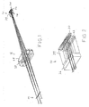
- a system in accordance with an embodiment of the invention includes an illumination source system 10, a rotationally symmetric macro lens group 12, and provides an illuminated line 14 at a light modulator.
- the illumination source 10 includes a substantially collimating laser illumination module 16 that includes a laser bar assembly 18 and laser bar assembly support structure 32, as well as a fast axis collimator 20 and a waveplate window 22.
- the illumination source 10 also includes an anamorphic beam expander 24 (including one or more anamorphic or cylinder elements) and a slow axis diffuser 26 such as a Fly's eye or Department of Defense Fly's eye or DOE optional slow axis far field.
- anamorphic means relating to, having or producing different optical imaging effects along mutually perpendicular radii (for a surface), or along mutually perpendicular axes (for an optical system).
- the substantially collimated FA lensed bar provides a clean interface for the sub illumination module (IM) specification.
- the second anamorphic element or group expands the FA for the proper scaling when used with the macro group and provides adjustment capability for alignment and integration of the IM into a line illumination modulator (LIM).
- the laser bar (or vicinity) becomes the illumination exit pupil.
- the second anamorphic lens may also provide total internal reflection in the slow axis direction to the width of the laser array.
- an engineered homogenizer such as a refractive fly's eye or other diffractive diffuser
- This homogenizer then becomes the illumination exit pupil.
- a pair of periscope prisms or mirror assemblies are used to split and displace the illumination exit pupil in the slow axis to create two half sized full divergence sources centered on the selected plus and minus orders of the dark field system being illuminated.
- a wave plate of appropriate thickness can be placed near the exit pupil and before the homogenizing element.
- the system provides that the IM interface requirements may be simplified to provide modular capability. Greater flexibility is also provided between IM source configurations. Greater flexibility is also provided between on-axis and off-axis illumination configurations. Higher yields may also be realized with use of lesser IMs for Low Cost off-axis applications.
- An optical system of an embodiment of the invention therefore, provides an on-axis illumination apparatus for projecting a line of light that includes a plurality of diode-lasers arranged in a linear diode-laser array, a first anamorphic lens to substantially collimate the fast axis, a second anamorphic lens (or group) to scale the fast axis, and a macro lens or group with positive rotationally symmetric optical power.
- the optical system may also include an engineered diffuser or group located after and near the second anamorphic lens and before and one focal length from the macro lens or group.
- the engineered diffuser may be defined as the exit pupil emitting a uniform angular SA field and may comprise one or more arrays of micro lenses with a refractive or diffractive cylindrical or acylindrical power in the slow axis with arbitrary pitch and scale.
- the optical system may further include a wave plate located after the first anamorphic lens but before the engineered diffuser to rotate the polarization to desired orientation or condition.
- the macro lens may be designed to minimize field curvature and other aberrations from a collimated field emitted from the exit pupil, and to generate a line image one focal length past the macro lens.
- systems of the invention may include a pair of folding mirrors or prisms located near the exit of the second anamorphic lens (or engineered diffuser if used) to split and displace the illumination for off-axis illumination.
- the spacing of the macro lens may maintain a one focal length optical path distance.
- a system in accordance with another embodiment of the invention includes an illumination source system 40, a rotationally symmetric macro lens group 42, and provides an illuminated line 44 at a light modulator.
- the illumination source 40 includes a substantially collimating laser illumination module 46 that includes a laser bar assembly 48 and laser bar assembly support structure 62, as well as a fast axis collimator 50 and a waveplate window 52.
- the illumination source 40 also includes an anamorphic beam expander 54 (including one or more anamorphic or cylinder elements) and a slow axis diffuser 56 such as a Fly's eye or Department of Defense Fly's eye or DOE optional slow axis far field. Illumination from the slow axis diffuser 56 is directed via sets of prisms 58, 60 and 64 toward the macro lens group 42 from an off axis direction as shown in Figures 6 and 8.
Landscapes
- Physics & Mathematics (AREA)
- General Physics & Mathematics (AREA)
- Optics & Photonics (AREA)
- Projection Apparatus (AREA)
- Semiconductor Lasers (AREA)
- Non-Portable Lighting Devices Or Systems Thereof (AREA)
Applications Claiming Priority (1)
| Application Number | Priority Date | Filing Date | Title |
|---|---|---|---|
| US66724205P | 2005-04-01 | 2005-04-01 |
Publications (2)
| Publication Number | Publication Date |
|---|---|
| EP1708009A2 true EP1708009A2 (fr) | 2006-10-04 |
| EP1708009A3 EP1708009A3 (fr) | 2006-11-08 |
Family
ID=36636288
Family Applications (1)
| Application Number | Title | Priority Date | Filing Date |
|---|---|---|---|
| EP06112177A Withdrawn EP1708009A3 (fr) | 2005-04-01 | 2006-04-03 | Système optique de projection d'une ligne d'illumination, à partir d'un réseau de lasers |
Country Status (2)
| Country | Link |
|---|---|
| US (1) | US20060221459A1 (fr) |
| EP (1) | EP1708009A3 (fr) |
Cited By (1)
| Publication number | Priority date | Publication date | Assignee | Title |
|---|---|---|---|---|
| CN107592916A (zh) * | 2015-05-06 | 2018-01-16 | 微软技术许可有限责任公司 | 用于快速轴扩张的光束投射 |
Families Citing this family (8)
| Publication number | Priority date | Publication date | Assignee | Title |
|---|---|---|---|---|
| JP2006330071A (ja) * | 2005-05-23 | 2006-12-07 | Fujifilm Holdings Corp | 線状ビーム生成光学装置 |
| US7629572B2 (en) * | 2005-10-28 | 2009-12-08 | Carl Zeiss Laser Optics Gmbh | Optical devices and related systems and methods |
| DE102008027231B4 (de) * | 2008-06-06 | 2016-03-03 | Limo Patentverwaltung Gmbh & Co. Kg | Vorrichtung zur Strahlformung |
| US9323063B2 (en) * | 2011-04-29 | 2016-04-26 | Dhpc Technologies, Inc. | Free-space combining of laser beam radiation |
| US8946594B2 (en) | 2011-11-04 | 2015-02-03 | Applied Materials, Inc. | Optical design for line generation using microlens array |
| US11592530B2 (en) | 2017-11-30 | 2023-02-28 | Cepton Technologies, Inc. | Detector designs for improved resolution in lidar systems |
| US11592527B2 (en) | 2018-02-16 | 2023-02-28 | Cepton Technologies, Inc. | Systems for incorporating LiDAR sensors in a headlamp module of a vehicle |
| TWI706185B (zh) | 2019-11-01 | 2020-10-01 | 大立光電股份有限公司 | 成像用光學系統、取像裝置及電子裝置 |
Family Cites Families (9)
| Publication number | Priority date | Publication date | Assignee | Title |
|---|---|---|---|---|
| JPH06160723A (ja) * | 1992-11-17 | 1994-06-07 | Mitsui Mining & Smelting Co Ltd | 暗視野照明装置 |
| JP4025366B2 (ja) * | 1995-01-11 | 2007-12-19 | ディラス ダイオーデンラーゼル ジーエムビーエイチ | レーザダイオードシステム用の光学装置 |
| DE69826950T2 (de) * | 1997-09-05 | 2006-02-23 | Sharp K.K. | Dunkelfeld-Projektionsanzeigegerät |
| DE59912912D1 (de) * | 1998-05-25 | 2006-01-19 | Fisba Optik Ag St Gallen | Verfahren und Vorrichtung zur Formung eines kollimierten Lichtstrahls aus den Emissionen mehrerer Lichtquellen |
| US6494371B1 (en) * | 2000-03-09 | 2002-12-17 | Coherent, Inc. | Diode-laser light projector for illuminating a linear array of light modulators |
| US6606173B2 (en) * | 2000-08-01 | 2003-08-12 | Riake Corporation | Illumination device and method for laser projector |
| US6773142B2 (en) * | 2002-01-07 | 2004-08-10 | Coherent, Inc. | Apparatus for projecting a line of light from a diode-laser array |
| US7016393B2 (en) * | 2003-09-22 | 2006-03-21 | Coherent, Inc. | Apparatus for projecting a line of light from a diode-laser array |
| DE50313072D1 (de) * | 2003-10-30 | 2010-10-21 | Limo Patentverwaltung Gmbh | Anordnung und Vorrichtung zur optischen Strahlbündeltransformation |
-
2006
- 2006-03-31 US US11/395,653 patent/US20060221459A1/en not_active Abandoned
- 2006-04-03 EP EP06112177A patent/EP1708009A3/fr not_active Withdrawn
Cited By (2)
| Publication number | Priority date | Publication date | Assignee | Title |
|---|---|---|---|---|
| CN107592916A (zh) * | 2015-05-06 | 2018-01-16 | 微软技术许可有限责任公司 | 用于快速轴扩张的光束投射 |
| US10326252B2 (en) * | 2015-05-06 | 2019-06-18 | Microsoft Technology Licensing, Llc | Beam projection for fast axis expansion |
Also Published As
| Publication number | Publication date |
|---|---|
| US20060221459A1 (en) | 2006-10-05 |
| EP1708009A3 (fr) | 2006-11-08 |
Similar Documents
| Publication | Publication Date | Title |
|---|---|---|
| US6680800B1 (en) | Device for symmetrizing the radiation emitted by linear optical transmitters | |
| US7016393B2 (en) | Apparatus for projecting a line of light from a diode-laser array | |
| US7413311B2 (en) | Speckle reduction in laser illuminated projection displays having a one-dimensional spatial light modulator | |
| US6069748A (en) | Laser line generator system | |
| EP2940503B1 (fr) | Multiplexeur, procédé de multiplexage et module à dl | |
| US6407870B1 (en) | Optical beam shaper and method for spatial redistribution of inhomogeneous beam | |
| US6337873B1 (en) | Optical arrangement for balancing the beam of one or more high power diode lasers arranged one above another | |
| JP2022546940A5 (fr) | ||
| US7110183B2 (en) | Device for the optical beam transformation of a linear arrangement of several light sources | |
| EP0097250A2 (fr) | Source lumineuse | |
| US10838217B2 (en) | Laser diode collimator and a pattern projecting device using same | |
| US20020110320A1 (en) | Illumination system for one-dimensional spatial light modulators employing multiple light sources | |
| US8970963B2 (en) | Multiple beam combiner for laser processing apparatus | |
| RU2686384C2 (ru) | Устройство для формирования лазерного излучения | |
| JPH10510933A (ja) | 複数のダイオードレーザアレイの放射光の集束及び整形のための装置 | |
| JPH08240793A (ja) | 球面収差の無い屈折楕円光学面 | |
| EP1708009A2 (fr) | Système optique de projection d'une ligne d'illumination, à partir d'un réseau de lasers | |
| CN102292663B (zh) | 用于使激光辐射均匀化的设备 | |
| CN100427995C (zh) | 用于使光均匀化的装置和用这种装置进行照明的结构 | |
| CN220671746U (zh) | 扫描激光扩束系统和ar显示装置 | |
| US20170299875A1 (en) | Single-emitter line beam system | |
| CZ200234A3 (cs) | Zařízení pro opatření tiskové formy obrazem s makrooptikou Offnerova typu | |
| KR920704172A (ko) | 프린터용 복사 소스 | |
| US6243210B1 (en) | Optical image rotating device used with afocal image relaying optics and laser diode array | |
| CN112904566A (zh) | 照明光学系统及光学显示设备 |
Legal Events
| Date | Code | Title | Description |
|---|---|---|---|
| PUAI | Public reference made under article 153(3) epc to a published international application that has entered the european phase |
Free format text: ORIGINAL CODE: 0009012 |
|
| AK | Designated contracting states |
Kind code of ref document: A2 Designated state(s): AT BE BG CH CY CZ DE DK EE ES FI FR GB GR HU IE IS IT LI LT LU LV MC NL PL PT RO SE SI SK TR |
|
| AX | Request for extension of the european patent |
Extension state: AL BA HR MK YU |
|
| PUAL | Search report despatched |
Free format text: ORIGINAL CODE: 0009013 |
|
| AK | Designated contracting states |
Kind code of ref document: A3 Designated state(s): AT BE BG CH CY CZ DE DK EE ES FI FR GB GR HU IE IS IT LI LT LU LV MC NL PL PT RO SE SI SK TR |
|
| AX | Request for extension of the european patent |
Extension state: AL BA HR MK YU |
|
| RIC1 | Information provided on ipc code assigned before grant |
Ipc: H04N 9/31 20060101ALI20061005BHEP Ipc: G02B 27/09 20060101AFI20060719BHEP |
|
| 17P | Request for examination filed |
Effective date: 20070508 |
|
| 17Q | First examination report despatched |
Effective date: 20070606 |
|
| AKX | Designation fees paid |
Designated state(s): DE FR GB |
|
| STAA | Information on the status of an ep patent application or granted ep patent |
Free format text: STATUS: THE APPLICATION IS DEEMED TO BE WITHDRAWN |
|
| 18D | Application deemed to be withdrawn |
Effective date: 20071218 |