EP1708308A2 - Vielfachsteckverbinder - Google Patents
Vielfachsteckverbinder Download PDFInfo
- Publication number
- EP1708308A2 EP1708308A2 EP06300260A EP06300260A EP1708308A2 EP 1708308 A2 EP1708308 A2 EP 1708308A2 EP 06300260 A EP06300260 A EP 06300260A EP 06300260 A EP06300260 A EP 06300260A EP 1708308 A2 EP1708308 A2 EP 1708308A2
- Authority
- EP
- European Patent Office
- Prior art keywords
- housing
- support
- locking element
- locking
- housing according
- Prior art date
- Legal status (The legal status is an assumption and is not a legal conclusion. Google has not performed a legal analysis and makes no representation as to the accuracy of the status listed.)
- Granted
Links
Images


Classifications
-
- H—ELECTRICITY
- H01—ELECTRIC ELEMENTS
- H01R—ELECTRICALLY-CONDUCTIVE CONNECTIONS; STRUCTURAL ASSOCIATIONS OF A PLURALITY OF MUTUALLY-INSULATED ELECTRICAL CONNECTING ELEMENTS; COUPLING DEVICES; CURRENT COLLECTORS
- H01R9/00—Structural associations of a plurality of mutually-insulated electrical connecting elements, e.g. terminal strips or terminal blocks; Terminals or binding posts mounted upon a base or in a case; Bases therefor
- H01R9/22—Bases, e.g. strip, block, panel
- H01R9/24—Terminal blocks
- H01R9/26—Clip-on terminal blocks for side-by-side rail- or strip-mounting
- H01R9/2608—Fastening means for mounting on support rail or strip
Definitions
- the present invention relates to a multicontact connector housing and such a multicontact connector, used in particular in the field of equipment on board an aircraft.
- the invention aims in particular to simplify the mounting operations of a multicontact connector on a support.
- the locking of the connector housing on the support can be performed manually, without tools, while ensuring a satisfactory attachment of the connector housing on the support.
- the locking member is slidably mounted on the housing body.
- the housing body and the locking element form a housing receiving the resilient return member.
- the locking element comprises at least one elastically deformable tab adapted to be applied to a first stop of the housing body when the locking element is in the unlocked position.
- the housing body comprises a second stop on which the elastically deformable tab can be applied to limit the stroke of the locking element when the latter is moved on a stroke beyond the locked position.
- the locking element remains integral with the housing body and it reduces or even eliminates the risk of misplacing one or more component parts of the connector housing.
- the locking element comprises a button connected to the elastically deformable tab, the button defining a bearing surface allowing a user to exercise, in particular with the aid of a finger, a force on the tab elastically deformable to lock the locking member on the support.
- the housing body advantageously comprises a slot through which the button extends.
- the locking element comprises a groove perpendicular to the sliding direction of the locking element and arranged to cooperate with said support when the locking element is in the locked position.
- the housing body and the locking element respectively comprise first and second registration surfaces, preferably planar, arranged so that, when the locking element is in the unlocked position, the first and second surfaces in a first relative position, in which these surfaces are for example offset, and when the locking element is in the locked position, the first and second registration surfaces are in a second relative position, in which these surfaces are for example substantially aligned.
- first and second registration surfaces may be, if desired, of different colors.
- the invention thus makes it possible to check visually whether the locking of the locking element has been carried out correctly.
- the locking element comprises an actuating part provided for example with a slot, arranged to provide a grip for a user to move, in particular with the aid of a tool, the locking element towards the unlocked position, against the force exerted by the elastic return member.
- an actuating part provided for example with a slot, arranged to provide a grip for a user to move, in particular with the aid of a tool, the locking element towards the unlocked position, against the force exerted by the elastic return member.
- the invention thus makes it possible to reset, if necessary, the locking element, for example by means of a screwdriver, for later use.
- the locking element is made in one piece, in particular plastic.
- the elastic return member comprises a spring, in particular a helical spring.
- the elastic return member may comprise any other element, for example an elastomer block.
- the fixing portion of the housing body comprises at least one tab, in particular deformable, arranged to be applied on the support when the housing is mounted on the support, in particular to achieve a mechanical and electrical connection of the connector on the support.
- the housing body is electrically conductive.
- the housing body comprises at least one housing arranged to receive at least one insulating block for mounting electrical contact elements.
- the invention also relates to a multicontact connector comprising a housing as defined above and electrical contact elements mounted in the connector housing.
- the invention also relates to a support for receiving at least one multicontact connector housing, the support comprising two substantially rectilinear and parallel edges, the support comprising, on at least one of the two edges, at least one indexing notch .
- the connector housing and the bracket can be arranged so that the housing can be mounted on the carrier only at a notch.
- the support may comprise two substantially coplanar edge portions, the attachment portion of the housing body engaging one of said edge portions and the locking member on the other edge portion.
- the invention further relates to an assembly comprising a support and a multicontact connector housing as defined above, the connector housing being removably mounted on the support.
- One of the first and second heights may, where appropriate, be zero.
- the invention facilitates the locking of the second housing on the first and prevent the unlocking of the second housing relative to the first when the assembly is subjected to vibration.
- the invention makes it possible to ensure relatively fine incrementation during locking while maintaining a sufficiently large tooth size for, on the one hand, their feasibility and, on the other hand, guaranteeing effective braking.
- the invention makes it possible to ensure that at least one of the locking zones is correctly engaged on the corresponding locking zone, because of the offset between the different locking zones.
- the difference between the first and second height is equal to a multiple of a half-step of the series of teeth.
- This configuration is advantageous when the locking cap of the second housing has exactly two elastically deformable tabs spaced along the first axis.
- the difference may be equal to a multiple of one third of the pitch of the series of teeth when each of the first and second housings comprise three interlocking zones spaced along the first axis.
- the tabs of the locking cap may all be identical or different.
- the locking zones of the first housing may have different numbers of teeth or not.
- the locking zones of at least one of the first and second housings are substantially aligned on the first axis.
- the first housing having a housing body, the locking regions of the first housing are preferably formed on a side face of the housing body.
- the elastically deformable tabs may each extend in a window of the locking cap, for example.
- the first housing comprises two pairs of locking zones that are symmetrical with respect to a plane, each pair preferably being made on a lateral face of the first housing
- the locking cover of the second housing may comprise two pairs of elastically deformable tabs, each tab being adapted to cooperate with an associated locking zone of the first housing.
- the first housing comprises at least one raised locking element, in particular a pin, and the locking cover at least one slot in which the locking element of the first housing can slide.
- Each slot of the locking cap may for example have a shape substantially in L.
- the locking cap is preferably slidably mounted on the body of the second housing.
- the body of the second housing comprises at least one guide groove, including two parallel guide grooves, in each of which can slide a flange of the locking cap.
- the locking cover comprises at least one elastically deformable tab, in particular two elastically deformable tabs, each being adapted to cooperate with a guide notch formed on the body of the second casing.
- the first and second housings may be of the circular type, the series of teeth of the first housing being able to extend for example along a circumference of the first housing, over an angular sector in particular of 360 °, and the elastically deformable tabs of the second housing being able to example have a cross section in an arc.
- At least one of the housing bodies is made for example of metal, plastic with a metallized coating or plastic incorporating a conductive filler.
- the subject of the invention is also a multicontact connector housing comprising at least two locking zones each having a series of teeth perpendicular to a first axis, the teeth of each series being regularly spaced apart, the locking zones being made on one side substantially plane of a housing body.
- Still another object of the invention is a multicontact connector housing having a housing body and a locking cap movable relative to the housing body, parallel to a first axis, between an unlocked position and a locked position, the locking cap comprising at least two elastically deformable tabs each provided with a locking zone with a series of teeth perpendicular to the first axis, the teeth of each series being regularly spaced apart.
- the invention also relates to a multicontact connector comprising one of the housings as defined above.
- the invention further relates, independently or in combination with the foregoing, to a multicontact connector housing having a housing body having a cable tie portion arranged to allow cables to be attached thereto, preferably using a fastener separate from the casing body, for example a conductive or insulating collar, the attachment portion protruding from the rear of the housing body and preferably having a substantially U-shaped cross section.
- the cable tie portion may form a cable exit area grounded with a fastener such as a conductive collar, in the case where the housing incorporates a conductive shield cover .
- the attachment portion is made in one piece or not with the rest of the housing body.
- the housing body may have a longitudinal recess extending substantially from a housing of the housing body for receiving an insulating block for electrical contact elements, to the attachment portion.
- This recess can allow for example to guide cables connected to the electrical contact elements, into the output zone of the connector housing.
- the longitudinal recess extends substantially perpendicular to the connection face.
- the housing comprises a conductive shielding cover arranged to be assembled to the housing body, preferably removably.
- the housing body and the shielding cap assembled together advantageously form a complete shielding surface.
- the housing can be used with a shielding cover mounted on it or without a shielding cover, depending on the desired functions.
- the shielding cap comprises a rear portion having a substantially U-shaped cross section, this rear portion being arranged to cooperate with the fastening portion of the casing body to form an opening. tubular housing for introducing cables into the housing.
- the shielding cap comprises at least one attachment shank protruding outside the tubular opening and arranged to allow to attach cables leaving the opening .
- the shielding cap comprises at least one resiliently deformable tab arranged to cooperate with the casing body snap-fastening in order to maintain the shielding cap on the casing body.
- This elastically deformable tab also makes it possible to ensure, if desired, a satisfactory mass continuity and / or shielding between the housing body and the shielding cap, in particular without the intermediary of an insert clamping element.
- the shielding cap comprises a plurality of elastically deformable tabs on two perpendicular edges of the shielding cap.
- At least one of the elastically deformable tabs is applied to the outside of the case body when the shielding cap is assembled on the case body.
- This elastically deformable tab may extend for example on a lower edge of the shielding cap.
- the shielding cap can be made for example of metal, plastic with a metallized coating or plastic incorporating a conductive filler.
- the connector housing may be of rectangular or circular type.
- the invention also relates to a multicontact connector comprising a housing as defined above, and contact elements mounted on the connector, these contact elements being connected to cables, which are secured to the attachment portion of the housing body, for example using an insert such as a collar, the housing may be without shielding cap.
- the invention also relates to a multicontact connector comprising a housing as defined above, and electrical contact elements mounted on the connector, the housing comprising a shielding cap mounted on a housing body, the contact elements being connected to cables fixed on a catching lug of the shielding cap, for example by means of an attached clamping piece such as a collar.
- the invention also relates to a multicontact connector comprising a housing as defined above, and electrical contact elements, these contact elements being connected to cables, these cables being introduced into a sheath with a fixed braid on the cable tie portion of the housing body and on the rear portion of the shield of the connector housing, this ground strap being maintained for example by means of a reported clamping piece such as a conductive collar.
- FIG. 1 shows a multicontact connector housing 1 of rectangular type mounted on a support 2.
- the housing 1 comprises a housing body 3 made for example of plastic material having a metallized coating.
- the body 3 comprises a base 5 of generally rectangular shape X axis on which is connected a fixing portion 6 having two parallel legs 7, as shown in Figure 2.
- These tabs 7 may be slightly elastically deformable to allow a satisfactory attachment of these tabs 7 on the support 2, as will be seen later.
- the base 5 has two grooves 9 parallel to the axis X, as illustrated in FIG.
- the base 5 further comprises a registration surface 10 extending perpendicularly to the axis X.
- the housing 1 further has a rectangular connection face 15 through which the housing 1 is coupled to a complementary multicontact connector housing.
- the housing 1 further has a housing 16 for receiving an insulating block for fixing electrical contact elements, this housing 16 being perpendicular to the X axis and extending above the base 5, as shown in FIG. Figure 1.
- the housing 1 has a longitudinal recess 17 extending along the X axis from the housing 16 into a cable attachment portion 18 protruding from the rear of the housing 1.
- the attachment portion 18 is arranged to allow cables to be attached to this portion, as will be seen later.
- This attachment portion 18 has a substantially U-shaped cross section.
- the housing 16 is defined by two lateral walls 20 on each of which two locking zones 21 are formed.
- each locking zone 21 comprises a series of teeth 22 perpendicular to a Y axis, the teeth of each series being regularly spaced apart, the two locking zones 21 being separated from one another by a space having a first height h 1 measured along the Y axis.
- the two locking zones 21 of a side face 20 are different from each other, the teeth 22 having for example a different length.
- the zones 21 may all be identical.
- the locking zones 21 of a lateral face 20 are symmetrical with the zones 21 on the other lateral face 20 with respect to a plane passing through the X and Y axes.
- the housing 1 comprises on each side face 20 two relief locking elements 24, formed in the example each considered by a pin, whose role will be explained later.
- the housing 1 further comprises a locking member 30 slidably mounted on the base 5 of the housing body 3.
- the locking element 30 is made of plastic material, preferably in one piece.
- the locking element 30 has two parallel ribs 31 intended to slidably engage the corresponding grooves 9 in the base 5, as illustrated in FIG. 5.
- the locking element 30 further has a substantially planar registration surface 32.
- the locking element 30 forms with the base 5 a housing 34 for receiving an elastic return member 35, as shown in Figures 3 and 4.
- the elastic return member 35 is constituted by a helical spring.
- the elastic return member 35 is applied at one end to the locking element 30 and at the opposite end to the housing body 3.
- the locking element 30 has an actuating portion 36 provided with a slot 37, this actuating portion 36 providing a grip for a user to move, using a tool such as a screwdriver, the locking element 30 against the force exerted by the resilient return member 35.
- the locking element 30 has, opposite the actuating part 36, an elastically deformable tab 38 arranged to be applied on a first abutment 39 of the casing body 3 when the locking element 30 is in a unlocked position, as shown in Figure 3.
- the first stop 39 is made for example on the underside of the base 5 of the casing body 3.
- the locking element 30 further comprises a button 40 connected to the elastically deformable tab 38, the button 40 defining a bearing surface 41 allowing a user to exercise, in particular with the aid of a finger, a force on the elastically deformable tab to disengage it from the first stop 39.
- the button 40 extends through a slot 44 made on the base 5 of the casing body 3.
- the housing body 3 further has a second stop 43 made on the underside of the base 5 and on which the elastically deformable tab 38 can be applied to limit the stroke of the locking element 30 when the latter is disengaged from the first stop 39 and the connector housing 1 is unassembled with the support 2.
- the locking element 30 can be separated from the housing body 3, when the connector housing 1 is not used, being for example stored before use.
- the locking element 30 has a groove 46 extending perpendicularly to the X axis and arranged to cooperate with the support 2 when the locking element is in a locked position, as illustrated in FIG. 4.
- the registration surface 10 of the housing body 3 and that of the locking element 30 extend substantially in continuity with one another when the locking element 30 is in the locked position, as illustrated in FIGS. Figures 4 and 5.
- the marking surfaces 10 and 32 are offset relative to each other along the X axis.
- the user can visually check whether the locking member 30 is in a proper locking position, if any.
- the support 2 has a longitudinal shape along an axis Z, perpendicular to the axis X.
- the support 2 has in cross section, perpendicular to the axis Z, a central portion 50 having a substantially U-shaped and two portions at the edge 51, on either side of this central portion 50, these edge portions 51 s extending in a plane defined by the X and Z axes.
- These portions 51 define parallel edges 52 parallel to the Z axis and have notches 53 regularly spaced on each edge 52, these notches 53 serving as indexing elements when mounting the housing 1 on the support 2.
- the support 2 is made of metal.
- the connector housing 1 is thus held on the support 2, on the one hand, thanks to the locking element 30 in engagement with an edge portion 51 of the support 2 and, on the other hand, thanks to the bracketed tabs 7 with the other portion at the edge 51, as illustrated in FIG. 2.
- These tabs 7 may be slightly elastically deformable, so as to apply with a residual stress on the edge portion 51 of the support 2.
- the connector housing 1 may be assembled, if desired, with a second multicontact connector housing 60 as shown in FIG.
- the second housing 60 has a connection face 61 through which the housing 60 is assembled with the housing 1.
- the second housing 60 includes a housing body 62 and a locking hood 63 movable relative to the housing body 62 parallel to the Y axis between an unlocked position and a locked position.
- the locking cover 63 comprises two pairs of elastically deformable tabs 65 each provided with a locking zone 66 with a series of teeth 67 perpendicular to the Y axis.
- each locking zone 66 of an elastically deformable tab 65 being intended to cooperate with a locking zone 21 of the housing 1 when the two housings 1 and 60 are assembled and the locking cap 63 is in the locked position.
- the locking zones 66 of the second housing 60 are separated from each other, along the Y axis, by a space having a second height h 2 measured along this axis Y, different from the height h 1 above.
- the series of teeth of the locking zones 21 and 66 on the housings 1 and 60 all have the same pitch and the difference between the first and second heights h 1 and h 2 is different from a multiple of no series of teeth.
- this difference between h 1 and h 2 is equal to a multiple of a half-step of the series of teeth.
- the difference h 1 is a multiple of a half-step of the series of teeth and h 2 multiple of a step of the series of teeth.
- the difference h 1 is a multiple of one step of the series of teeth and h 2 which is a multiple of a half-step of the series of teeth.
- This offset of a half-step makes it possible to ensure a relatively fine incrementation during the locking of the cover 63 on the casing body 1.
- the tabs 65 are each made in a window 69 of the locking cap 63.
- the locking cover 63 has two pairs of slots 70 in each of which a locking element 24 of the housing 1 can slide when the cover 63 moves from the unlocked position to the locked position, so that when the cover is in position locked, the cooperation of the locking element 24 with the corresponding slot 70 secures the two housings 1 and 60 together in the X direction.
- each slot 70 has a shape substantially in L.
- the locking cover 63 is slidably mounted on the housing body 62.
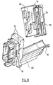
- the housing body 62 may comprise two parallel guiding grooves 72 and in each of which can slide a flange 73 of the locking cover 63, as illustrated in FIG. 8.
- the locking cover 63 comprises two elastically deformable tabs 74, each being able to cooperate with a guide notch 75 made on the casing body 62.
- the casing body 62 has a cable attachment portion 18 similar to the casing 1.
- the assembly of the housings 1 and 60 is made in a relatively simple manner, bringing these two housings facing each other, engaging the reliefs 24 in the slots 70 and sliding the cover 63 along the Y axis in order to immobilize the cover 63 with respect to the housing body 62 through the cooperation of the locking zones 21 and 66 and that of the locking elements 24 in the slots 70.
- the connector housing 60 receives an insulating block 90 fixed in the housing 16 and having cells into which electrical contact elements 91 are introduced.
- Each contact element 91 is connected to a cable 92.
- the wire harness 92 is fixed to the cable tie portion 18 of the housing 60 by means of a clamping collar 93 made of a conductive material, for example metal.
- the connector housing 1 may comprise, if desired, a shielding cap 95 made of, for example, metal, electrically conductive plastic material or plastic material with a conductive coating.
- the shielding cap 95 has two leading edges 96 extending parallel to the Y axis and two lower edges 97 extending parallel to the X axis.
- the shielding cap 95 has on its edges 96 and 97 elastically deformable tabs 98 and 99, respectively.
- the housing body 3 has grooves 100 parallel to the Y axis and in which the resiliently deformable tabs 98 of the shielding cap 95 can snap into engagement.
- the elastically deformable tabs 99 are applied on an outer face 102 of the casing body 3.
- the shielding cap 95 comprises a rear portion 105 having a substantially U-shaped cross-section, this rear portion 105 being arranged to cooperate with the fastening portion 18 of the casing body 3 in order to form a tubular opening 106 for introducing cables in the housing, as shown in Figures 9 and 10.
- the shielding cap 95 further includes a hooking tail 108 projecting out of the tubular opening 106 and arranged to allow attachment of cables exiting the opening 106 as shown in FIG. 11.
- the wire harness 92 may be attached to the attachment shank 108, for example by means of a clamping collar 110 made of a conductive material, this collar 110 being placed on the attachment shank 108.
- the invention thus offers a satisfactory modularity as regards the use of the various elements of the connector.
- the cables 92 can be introduced into a sheath with a ground strap 112 fixed on the cable tie portion of the housing body and on the rear portion of the shielding cap 95.
- This mass braid 112 is held for example by means of a clamping piece 113 attached to this braid 112.
- One of the heights h 1 and h 2 may for example be zero, in which case two locking zones 21 of the housing body 3 may for example be adjacent to each other.
Landscapes
- Details Of Connecting Devices For Male And Female Coupling (AREA)
- Connector Housings Or Holding Contact Members (AREA)
- Mechanical Coupling Of Light Guides (AREA)
- Cable Accessories (AREA)
- Apparatus For Radiation Diagnosis (AREA)
Applications Claiming Priority (1)
| Application Number | Priority Date | Filing Date | Title |
|---|---|---|---|
| FR0550844A FR2884061B1 (fr) | 2005-03-31 | 2005-03-31 | Connecteur multicontacts |
Publications (3)
| Publication Number | Publication Date |
|---|---|
| EP1708308A2 true EP1708308A2 (de) | 2006-10-04 |
| EP1708308A3 EP1708308A3 (de) | 2007-05-09 |
| EP1708308B1 EP1708308B1 (de) | 2008-12-17 |
Family
ID=35385867
Family Applications (1)
| Application Number | Title | Priority Date | Filing Date |
|---|---|---|---|
| EP06300260A Expired - Lifetime EP1708308B1 (de) | 2005-03-31 | 2006-03-22 | Vielfachsteckverbinder |
Country Status (6)
| Country | Link |
|---|---|
| US (1) | US7575484B2 (de) |
| EP (1) | EP1708308B1 (de) |
| AT (1) | ATE418167T1 (de) |
| DE (1) | DE602006004238D1 (de) |
| ES (1) | ES2319567T3 (de) |
| FR (1) | FR2884061B1 (de) |
Cited By (1)
| Publication number | Priority date | Publication date | Assignee | Title |
|---|---|---|---|---|
| GB2433846B (en) * | 2005-12-27 | 2010-07-07 | Boeing Co | Electrical quick lock interconnect |
Families Citing this family (9)
| Publication number | Priority date | Publication date | Assignee | Title |
|---|---|---|---|---|
| CN101128098B (zh) * | 2006-08-17 | 2010-05-12 | 浙江正泰电器股份有限公司 | 模数化电器的安装固定装置 |
| JP5914094B2 (ja) * | 2012-03-29 | 2016-05-11 | 株式会社サンコーシヤ | 保安器のdinレールへの取付装置 |
| US9136648B2 (en) * | 2012-07-12 | 2015-09-15 | Rockwell Automation Technologies, Inc. | Din or panel ground integral to connector body |
| US9397462B2 (en) * | 2012-12-28 | 2016-07-19 | General Electric Company | Rail mounting system and detaching method |
| DE102013112101B4 (de) * | 2013-11-04 | 2018-05-09 | Phoenix Contact Gmbh & Co. Kg | Komponentenaufbausystem |
| EP3246995B1 (de) * | 2016-05-17 | 2020-05-13 | Wöhner GmbH & Co. KG Elektrotechnische Systeme | Stromsammelschienensystem |
| FR3098032B1 (fr) * | 2019-06-26 | 2022-02-25 | Radiall Sa | Ensemble de connexion à bornier à pluralité de modules de connexion de puissance indépendants et système de verrouillage/déverrouillage rapide des modules à un rail destiné à être fixé sur une structure, notamment une structure d’aéronef. |
| US10971864B1 (en) * | 2019-09-30 | 2021-04-06 | BAKC Capital Group | DIN rail shield |
| US12485759B2 (en) | 2023-11-01 | 2025-12-02 | Textron Innovations Inc. | Component retainer |
Family Cites Families (35)
| Publication number | Priority date | Publication date | Assignee | Title |
|---|---|---|---|---|
| DE19537528C2 (de) * | 1995-09-29 | 2000-01-13 | Krone Ag | Anschlußeinrichtung für die Fernmelde- und Datentechnik |
| DE1939706U (de) * | 1960-07-11 | 1966-06-02 | Josef Eisert | Schaltanlagen-reihenklemme mit montagefuss zur montage auf tragschienen und in montagefuss untergebrachtem befestigungsschloss. |
| US3236975A (en) * | 1961-11-24 | 1966-02-22 | Allen Bradley Co | Removable segment, track-mounted terminal block |
| US3293593A (en) * | 1963-11-29 | 1966-12-20 | Square D Co | Modular terminal block |
| CH516232A (de) * | 1971-04-01 | 1971-11-30 | Oskar Woertz Inh H & O Woertz | Schraubenlose elektrische Schnell-Verbindungsklemme |
| DE7811450U1 (de) * | 1978-04-17 | 1978-07-27 | C. A. Weidmueller Kg, 4930 Detmold | |
| CH646278A5 (de) * | 1978-07-29 | 1984-11-15 | Weidmueller Kg C | Reihenklemme mit schutzleiteranschluss. |
| FR2502449A1 (fr) * | 1981-03-23 | 1982-09-24 | Alsthom Cgee | Dispositif de fixation d'un appareil sur profiles supports |
| US5030139A (en) * | 1988-05-16 | 1991-07-09 | Paul Huska | Clamping screw device |
| US4832628A (en) * | 1988-05-16 | 1989-05-23 | Paul Huska | Terminal block insert device |
| US5037310A (en) * | 1989-12-06 | 1991-08-06 | Gespac, Inc. | Connector apparatus and method for distributed control modules used in computer networks |
| US5145418A (en) * | 1991-06-07 | 1992-09-08 | Allen-Bradley Company, Inc. | Terminal block segment with feet for mounting on tracks of two different widths |
| DE9213118U1 (de) * | 1992-09-30 | 1993-02-04 | Phoenix Contact GmbH & Co., 4933 Blomberg | Klemmenanordnung |
| US5694288A (en) * | 1995-02-01 | 1997-12-02 | Square D Company | Mounting arrangement for mounting a circuit breaker to a rail |
| DE29515982U1 (de) * | 1995-09-29 | 1996-10-31 | Krone Ag, 14167 Berlin | Erdungsbügel, insbesondere zur Verwendung in einer Anschlußeinrichtung für die Fernmelde- und Datentechnik |
| US6172875B1 (en) * | 1998-11-17 | 2001-01-09 | Rockwell Technologies, Llc | Programmable logic controller module assembly and locking system |
| US6146213A (en) * | 1998-12-10 | 2000-11-14 | Yoon; Heung-Sik | Wire connection with exchangeable securing member for electric connection terminal assembly |
| US6062914A (en) * | 1999-03-17 | 2000-05-16 | Carlingswitch, Inc. | Circuit breaker plug in bracket and auxiliary/alarm switch connector for use therewith |
| ATE349792T1 (de) * | 1999-04-14 | 2007-01-15 | Whitaker Corp | Befestigungsvorrichtung zur befestigung von modulen auf einer schiene |
| US6129595A (en) * | 1999-04-14 | 2000-10-10 | General Electric Company | Three phase sub feed lug accessory |
| KR100322350B1 (ko) * | 2000-01-19 | 2002-02-07 | 윤흥식 | 단자대의 링크스트립 |
| DE10005818A1 (de) * | 2000-02-10 | 2001-08-16 | Moeller Gmbh | Vorrichtung zur Befestigung von Schaltgeräten auf Tragschienen |
| US20010034165A1 (en) * | 2000-03-10 | 2001-10-25 | Landis John M. | Terminal block connector |
| US6425770B1 (en) * | 2000-04-14 | 2002-07-30 | Rockwell Automation Technologies, Inc. | Input/output device having removable module |
| JP4524872B2 (ja) * | 2000-07-07 | 2010-08-18 | Smc株式会社 | 信号入出力装置 |
| EP1317783B1 (de) * | 2000-09-12 | 2006-10-18 | Tyco Electronics AMP GmbH | Modulares verbindungssystem für ethernet-anwendungen im industriellen sektor |
| US6680842B1 (en) * | 2003-04-21 | 2004-01-20 | Pedro R. Pelaez | Front mount circuit breaker assembly |
| WO2004114466A1 (en) * | 2003-06-25 | 2004-12-29 | Crevis Co., Ltd. | Signal processing module of industrial machines |
| US7371979B2 (en) * | 2003-11-05 | 2008-05-13 | Tyco Electronics Brasil Ltda. | Electrical interconnection arrangement |
| US7011551B2 (en) * | 2004-05-06 | 2006-03-14 | Johansen Arnold W | Electrical terminal block |
| US7156694B1 (en) * | 2004-11-08 | 2007-01-02 | Anderson Kenneth E | Electrical outlet plug strip |
| DE202005004927U1 (de) * | 2005-03-23 | 2005-06-02 | Ria-Btr Produktions-Gmbh | Anschlusselement |
| US7286340B2 (en) * | 2005-12-09 | 2007-10-23 | Eaton Corporation | Adjustable adapter for mounting electrical switching apparatus and enclosure assembly employing the same |
| US7374453B1 (en) * | 2006-12-28 | 2008-05-20 | General Electric Company | Enclosure-to-rail retaining system and method |
| US7413487B1 (en) * | 2007-04-03 | 2008-08-19 | Surtec Industries Inc. | Signal line connector |
-
2005
- 2005-03-31 FR FR0550844A patent/FR2884061B1/fr not_active Expired - Fee Related
-
2006
- 2006-03-22 EP EP06300260A patent/EP1708308B1/de not_active Expired - Lifetime
- 2006-03-22 AT AT06300260T patent/ATE418167T1/de not_active IP Right Cessation
- 2006-03-22 DE DE602006004238T patent/DE602006004238D1/de not_active Expired - Lifetime
- 2006-03-22 ES ES06300260T patent/ES2319567T3/es not_active Expired - Lifetime
- 2006-03-29 US US11/391,303 patent/US7575484B2/en active Active
Cited By (1)
| Publication number | Priority date | Publication date | Assignee | Title |
|---|---|---|---|---|
| GB2433846B (en) * | 2005-12-27 | 2010-07-07 | Boeing Co | Electrical quick lock interconnect |
Also Published As
| Publication number | Publication date |
|---|---|
| EP1708308B1 (de) | 2008-12-17 |
| US20060223372A1 (en) | 2006-10-05 |
| FR2884061A1 (fr) | 2006-10-06 |
| ATE418167T1 (de) | 2009-01-15 |
| DE602006004238D1 (de) | 2009-01-29 |
| EP1708308A3 (de) | 2007-05-09 |
| ES2319567T3 (es) | 2009-05-08 |
| FR2884061B1 (fr) | 2011-08-05 |
| US7575484B2 (en) | 2009-08-18 |
Similar Documents
| Publication | Publication Date | Title |
|---|---|---|
| EP1708313B1 (de) | Vielfachsteckverbinder | |
| EP3048674B1 (de) | Mehrkontaktstecker | |
| EP1708308B1 (de) | Vielfachsteckverbinder | |
| EP2654137B1 (de) | Sockel eines Multikontaktanschlusses zum Schnellbefestigen auf einer Platte und entsprechendes Montage-/Demontage-Verfahren | |
| FR2942935A1 (fr) | Dispositif de retenue de carte de circuit imprime | |
| EP2558734A1 (de) | Mechanische anordnung mit vereinfachter verwendung | |
| EP2120298B1 (de) | Multikontaktanschluss mit in der Dicke des Gehäuses integriertem Verschlussteil | |
| WO2012076330A1 (fr) | Goulotte de reception d'elements allonges, son procede de montage et ensemble comprenant un support et une telle goulotte | |
| EP1670301B1 (de) | Verbindungsanordnung bestehend aus einem Halter mit einer Öffnung und einem Verbindergehäuse montiert auf dem Halter | |
| EP0700084A1 (de) | Apparat zur Befestigung von elektronischen Leistungsbauteilen an einem Kühlkörper und Montageverfahren auf einer Leiterplatte | |
| EP2839087B1 (de) | Ratschenverriegelungssystem | |
| EP2963747A1 (de) | Montage eines startsystems auf einer vielzahl von befestigungsschienen | |
| EP4150712A1 (de) | Elektrische verbindungsvorrichtung zur erdung eines elektrischen leiters | |
| FR2927197A1 (fr) | Dispositif de fixation d'une batterie d'accumulateurs. | |
| FR3063840A1 (fr) | Dispositif electrique comprenant un element mecanique amovible pour son verrouillage sur un rail support, notamment un rail de type din | |
| WO2017178724A1 (fr) | Agencement d'un bouclier et d'un element de carrosserie d'un vehicule automobile, notamment d'un element de carrosserie en tole | |
| EP4086466A1 (de) | Befestigungsvorrichtung | |
| FR2915026A1 (fr) | Dispositif de connexion de cables plats comportant chacun plusieurs conducteurs. | |
| EP1965468A1 (de) | Ausrüstungsteil eines Kraftfahrzeugs und zugehöriges Kraftfahrzeug | |
| FR3092149A1 (fr) | Dispositif de fixation | |
| FR2978520A1 (fr) | Ensemble d'agrafage pour le maintien de cables montable sans accessibilite et procede de montage correspondant | |
| EP1211760A1 (de) | Hand-Crimpwerkzeug mit abnehmbarem Zufuhrmagazin | |
| CA3040579A1 (fr) | Appareil electrique comprenant un dispositif de verrouillage pour rail de fixation | |
| FR2967833A1 (fr) | Appareil electrique a fixation reversible, demontable sans outil | |
| FR3033727A1 (fr) | Outil pour le serrage et/ou le desserrage d'un element de fixation |
Legal Events
| Date | Code | Title | Description |
|---|---|---|---|
| PUAI | Public reference made under article 153(3) epc to a published international application that has entered the european phase |
Free format text: ORIGINAL CODE: 0009012 |
|
| AK | Designated contracting states |
Kind code of ref document: A2 Designated state(s): AT BE BG CH CY CZ DE DK EE ES FI FR GB GR HU IE IS IT LI LT LU LV MC NL PL PT RO SE SI SK TR |
|
| AX | Request for extension of the european patent |
Extension state: AL BA HR MK YU |
|
| PUAL | Search report despatched |
Free format text: ORIGINAL CODE: 0009013 |
|
| AK | Designated contracting states |
Kind code of ref document: A3 Designated state(s): AT BE BG CH CY CZ DE DK EE ES FI FR GB GR HU IE IS IT LI LT LU LV MC NL PL PT RO SE SI SK TR |
|
| AX | Request for extension of the european patent |
Extension state: AL BA HR MK YU |
|
| 17P | Request for examination filed |
Effective date: 20071009 |
|
| 17Q | First examination report despatched |
Effective date: 20071115 |
|
| AKX | Designation fees paid |
Designated state(s): AT BE BG CH CY CZ DE DK EE ES FI FR GB GR HU IE IS IT LI LT LU LV MC NL PL PT RO SE SI SK TR |
|
| GRAP | Despatch of communication of intention to grant a patent |
Free format text: ORIGINAL CODE: EPIDOSNIGR1 |
|
| GRAS | Grant fee paid |
Free format text: ORIGINAL CODE: EPIDOSNIGR3 |
|
| GRAA | (expected) grant |
Free format text: ORIGINAL CODE: 0009210 |
|
| AK | Designated contracting states |
Kind code of ref document: B1 Designated state(s): AT BE BG CH CY CZ DE DK EE ES FI FR GB GR HU IE IS IT LI LT LU LV MC NL PL PT RO SE SI SK TR |
|
| REG | Reference to a national code |
Ref country code: GB Ref legal event code: FG4D Free format text: NOT ENGLISH |
|
| REG | Reference to a national code |
Ref country code: CH Ref legal event code: EP |
|
| REG | Reference to a national code |
Ref country code: IE Ref legal event code: FG4D Free format text: LANGUAGE OF EP DOCUMENT: FRENCH |
|
| REF | Corresponds to: |
Ref document number: 602006004238 Country of ref document: DE Date of ref document: 20090129 Kind code of ref document: P |
|
| PG25 | Lapsed in a contracting state [announced via postgrant information from national office to epo] |
Ref country code: LT Free format text: LAPSE BECAUSE OF FAILURE TO SUBMIT A TRANSLATION OF THE DESCRIPTION OR TO PAY THE FEE WITHIN THE PRESCRIBED TIME-LIMIT Effective date: 20081217 |
|
| REG | Reference to a national code |
Ref country code: ES Ref legal event code: FG2A Ref document number: 2319567 Country of ref document: ES Kind code of ref document: T3 |
|
| PG25 | Lapsed in a contracting state [announced via postgrant information from national office to epo] |
Ref country code: NL Free format text: LAPSE BECAUSE OF FAILURE TO SUBMIT A TRANSLATION OF THE DESCRIPTION OR TO PAY THE FEE WITHIN THE PRESCRIBED TIME-LIMIT Effective date: 20081217 Ref country code: LV Free format text: LAPSE BECAUSE OF FAILURE TO SUBMIT A TRANSLATION OF THE DESCRIPTION OR TO PAY THE FEE WITHIN THE PRESCRIBED TIME-LIMIT Effective date: 20081217 Ref country code: FI Free format text: LAPSE BECAUSE OF FAILURE TO SUBMIT A TRANSLATION OF THE DESCRIPTION OR TO PAY THE FEE WITHIN THE PRESCRIBED TIME-LIMIT Effective date: 20081217 Ref country code: PL Free format text: LAPSE BECAUSE OF FAILURE TO SUBMIT A TRANSLATION OF THE DESCRIPTION OR TO PAY THE FEE WITHIN THE PRESCRIBED TIME-LIMIT Effective date: 20081217 Ref country code: SI Free format text: LAPSE BECAUSE OF FAILURE TO SUBMIT A TRANSLATION OF THE DESCRIPTION OR TO PAY THE FEE WITHIN THE PRESCRIBED TIME-LIMIT Effective date: 20081217 |
|
| NLV1 | Nl: lapsed or annulled due to failure to fulfill the requirements of art. 29p and 29m of the patents act | ||
| REG | Reference to a national code |
Ref country code: IE Ref legal event code: FD4D |
|
| PG25 | Lapsed in a contracting state [announced via postgrant information from national office to epo] |
Ref country code: BG Free format text: LAPSE BECAUSE OF FAILURE TO SUBMIT A TRANSLATION OF THE DESCRIPTION OR TO PAY THE FEE WITHIN THE PRESCRIBED TIME-LIMIT Effective date: 20090317 Ref country code: RO Free format text: LAPSE BECAUSE OF FAILURE TO SUBMIT A TRANSLATION OF THE DESCRIPTION OR TO PAY THE FEE WITHIN THE PRESCRIBED TIME-LIMIT Effective date: 20081217 Ref country code: EE Free format text: LAPSE BECAUSE OF FAILURE TO SUBMIT A TRANSLATION OF THE DESCRIPTION OR TO PAY THE FEE WITHIN THE PRESCRIBED TIME-LIMIT Effective date: 20081217 Ref country code: IE Free format text: LAPSE BECAUSE OF FAILURE TO SUBMIT A TRANSLATION OF THE DESCRIPTION OR TO PAY THE FEE WITHIN THE PRESCRIBED TIME-LIMIT Effective date: 20081217 |
|
| PG25 | Lapsed in a contracting state [announced via postgrant information from national office to epo] |
Ref country code: CZ Free format text: LAPSE BECAUSE OF FAILURE TO SUBMIT A TRANSLATION OF THE DESCRIPTION OR TO PAY THE FEE WITHIN THE PRESCRIBED TIME-LIMIT Effective date: 20081217 Ref country code: SE Free format text: LAPSE BECAUSE OF FAILURE TO SUBMIT A TRANSLATION OF THE DESCRIPTION OR TO PAY THE FEE WITHIN THE PRESCRIBED TIME-LIMIT Effective date: 20090317 Ref country code: IS Free format text: LAPSE BECAUSE OF FAILURE TO SUBMIT A TRANSLATION OF THE DESCRIPTION OR TO PAY THE FEE WITHIN THE PRESCRIBED TIME-LIMIT Effective date: 20090417 Ref country code: PT Free format text: LAPSE BECAUSE OF FAILURE TO SUBMIT A TRANSLATION OF THE DESCRIPTION OR TO PAY THE FEE WITHIN THE PRESCRIBED TIME-LIMIT Effective date: 20090518 Ref country code: AT Free format text: LAPSE BECAUSE OF FAILURE TO SUBMIT A TRANSLATION OF THE DESCRIPTION OR TO PAY THE FEE WITHIN THE PRESCRIBED TIME-LIMIT Effective date: 20081217 |
|
| BERE | Be: lapsed |
Owner name: RADIALL Effective date: 20090331 |
|
| PG25 | Lapsed in a contracting state [announced via postgrant information from national office to epo] |
Ref country code: SK Free format text: LAPSE BECAUSE OF FAILURE TO SUBMIT A TRANSLATION OF THE DESCRIPTION OR TO PAY THE FEE WITHIN THE PRESCRIBED TIME-LIMIT Effective date: 20081217 |
|
| PLBE | No opposition filed within time limit |
Free format text: ORIGINAL CODE: 0009261 |
|
| STAA | Information on the status of an ep patent application or granted ep patent |
Free format text: STATUS: NO OPPOSITION FILED WITHIN TIME LIMIT |
|
| PG25 | Lapsed in a contracting state [announced via postgrant information from national office to epo] |
Ref country code: DK Free format text: LAPSE BECAUSE OF FAILURE TO SUBMIT A TRANSLATION OF THE DESCRIPTION OR TO PAY THE FEE WITHIN THE PRESCRIBED TIME-LIMIT Effective date: 20081217 Ref country code: MC Free format text: LAPSE BECAUSE OF NON-PAYMENT OF DUE FEES Effective date: 20090331 |
|
| 26N | No opposition filed |
Effective date: 20090918 |
|
| PG25 | Lapsed in a contracting state [announced via postgrant information from national office to epo] |
Ref country code: BE Free format text: LAPSE BECAUSE OF NON-PAYMENT OF DUE FEES Effective date: 20090331 |
|
| PG25 | Lapsed in a contracting state [announced via postgrant information from national office to epo] |
Ref country code: GR Free format text: LAPSE BECAUSE OF FAILURE TO SUBMIT A TRANSLATION OF THE DESCRIPTION OR TO PAY THE FEE WITHIN THE PRESCRIBED TIME-LIMIT Effective date: 20090318 |
|
| REG | Reference to a national code |
Ref country code: CH Ref legal event code: PL |
|
| PG25 | Lapsed in a contracting state [announced via postgrant information from national office to epo] |
Ref country code: LI Free format text: LAPSE BECAUSE OF NON-PAYMENT OF DUE FEES Effective date: 20100331 Ref country code: CH Free format text: LAPSE BECAUSE OF NON-PAYMENT OF DUE FEES Effective date: 20100331 |
|
| PG25 | Lapsed in a contracting state [announced via postgrant information from national office to epo] |
Ref country code: LU Free format text: LAPSE BECAUSE OF NON-PAYMENT OF DUE FEES Effective date: 20090322 |
|
| PG25 | Lapsed in a contracting state [announced via postgrant information from national office to epo] |
Ref country code: HU Free format text: LAPSE BECAUSE OF FAILURE TO SUBMIT A TRANSLATION OF THE DESCRIPTION OR TO PAY THE FEE WITHIN THE PRESCRIBED TIME-LIMIT Effective date: 20090618 |
|
| PG25 | Lapsed in a contracting state [announced via postgrant information from national office to epo] |
Ref country code: TR Free format text: LAPSE BECAUSE OF FAILURE TO SUBMIT A TRANSLATION OF THE DESCRIPTION OR TO PAY THE FEE WITHIN THE PRESCRIBED TIME-LIMIT Effective date: 20081217 |
|
| PG25 | Lapsed in a contracting state [announced via postgrant information from national office to epo] |
Ref country code: CY Free format text: LAPSE BECAUSE OF FAILURE TO SUBMIT A TRANSLATION OF THE DESCRIPTION OR TO PAY THE FEE WITHIN THE PRESCRIBED TIME-LIMIT Effective date: 20081217 |
|
| REG | Reference to a national code |
Ref country code: FR Ref legal event code: PLFP Year of fee payment: 11 |
|
| REG | Reference to a national code |
Ref country code: FR Ref legal event code: PLFP Year of fee payment: 12 |
|
| REG | Reference to a national code |
Ref country code: FR Ref legal event code: PLFP Year of fee payment: 13 |
|
| PGFP | Annual fee paid to national office [announced via postgrant information from national office to epo] |
Ref country code: DE Payment date: 20250218 Year of fee payment: 20 |
|
| PGFP | Annual fee paid to national office [announced via postgrant information from national office to epo] |
Ref country code: FR Payment date: 20250218 Year of fee payment: 20 |
|
| PGFP | Annual fee paid to national office [announced via postgrant information from national office to epo] |
Ref country code: IT Payment date: 20250218 Year of fee payment: 20 Ref country code: GB Payment date: 20250221 Year of fee payment: 20 |
|
| PGFP | Annual fee paid to national office [announced via postgrant information from national office to epo] |
Ref country code: ES Payment date: 20250401 Year of fee payment: 20 |
|
| REG | Reference to a national code |
Ref country code: DE Ref legal event code: R071 Ref document number: 602006004238 Country of ref document: DE |
|
| REG | Reference to a national code |
Ref country code: ES Ref legal event code: FD2A Effective date: 20260327 |
|
| PG25 | Lapsed in a contracting state [announced via postgrant information from national office to epo] |
Ref country code: ES Free format text: LAPSE BECAUSE OF EXPIRATION OF PROTECTION Effective date: 20260323 |
|
| REG | Reference to a national code |
Ref country code: GB Ref legal event code: PE20 Expiry date: 20260321 |