EP1708320A1 - Source de pompage pour l'accord d'un laser - Google Patents
Source de pompage pour l'accord d'un laser Download PDFInfo
- Publication number
- EP1708320A1 EP1708320A1 EP06075111A EP06075111A EP1708320A1 EP 1708320 A1 EP1708320 A1 EP 1708320A1 EP 06075111 A EP06075111 A EP 06075111A EP 06075111 A EP06075111 A EP 06075111A EP 1708320 A1 EP1708320 A1 EP 1708320A1
- Authority
- EP
- European Patent Office
- Prior art keywords
- solid state
- array
- gain medium
- modulating
- auxiliary
- Prior art date
- Legal status (The legal status is an assumption and is not a legal conclusion. Google has not performed a legal analysis and makes no representation as to the accuracy of the status listed.)
- Withdrawn
Links
- 239000007787 solid Substances 0.000 claims abstract description 54
- 230000003287 optical effect Effects 0.000 claims abstract description 31
- 238000000034 method Methods 0.000 claims abstract description 20
- 238000003491 array Methods 0.000 claims abstract description 19
- 230000000694 effects Effects 0.000 claims abstract description 16
- 230000004075 alteration Effects 0.000 claims description 9
- 230000008878 coupling Effects 0.000 claims description 4
- 238000010168 coupling process Methods 0.000 claims description 4
- 238000005859 coupling reaction Methods 0.000 claims description 4
- 239000000523 sample Substances 0.000 description 9
- 238000005259 measurement Methods 0.000 description 6
- 239000000835 fiber Substances 0.000 description 5
- 239000000463 material Substances 0.000 description 5
- 230000003044 adaptive effect Effects 0.000 description 4
- 238000005086 pumping Methods 0.000 description 4
- 230000021615 conjugation Effects 0.000 description 3
- JNDMLEXHDPKVFC-UHFFFAOYSA-N aluminum;oxygen(2-);yttrium(3+) Chemical compound [O-2].[O-2].[O-2].[Al+3].[Y+3] JNDMLEXHDPKVFC-UHFFFAOYSA-N 0.000 description 2
- 238000001816 cooling Methods 0.000 description 2
- 238000000151 deposition Methods 0.000 description 2
- 238000013461 design Methods 0.000 description 2
- 238000005535 overpotential deposition Methods 0.000 description 2
- 229910019901 yttrium aluminum garnet Inorganic materials 0.000 description 2
- 230000032683 aging Effects 0.000 description 1
- 230000003667 anti-reflective effect Effects 0.000 description 1
- 238000013459 approach Methods 0.000 description 1
- 230000005540 biological transmission Effects 0.000 description 1
- 230000000903 blocking effect Effects 0.000 description 1
- 238000007796 conventional method Methods 0.000 description 1
- 238000012937 correction Methods 0.000 description 1
- 230000003247 decreasing effect Effects 0.000 description 1
- 230000008021 deposition Effects 0.000 description 1
- 238000001514 detection method Methods 0.000 description 1
- 238000000605 extraction Methods 0.000 description 1
- 238000003384 imaging method Methods 0.000 description 1
- 230000001788 irregular Effects 0.000 description 1
- 230000031700 light absorption Effects 0.000 description 1
- 238000012986 modification Methods 0.000 description 1
- 230000004048 modification Effects 0.000 description 1
- 239000013307 optical fiber Substances 0.000 description 1
- 238000004806 packaging method and process Methods 0.000 description 1
- 230000000737 periodic effect Effects 0.000 description 1
- 230000008569 process Effects 0.000 description 1
- 230000000644 propagated effect Effects 0.000 description 1
- 229910052761 rare earth metal Inorganic materials 0.000 description 1
- 150000002910 rare earth metals Chemical class 0.000 description 1
Images

Classifications
-
- H—ELECTRICITY
- H01—ELECTRIC ELEMENTS
- H01S—DEVICES USING THE PROCESS OF LIGHT AMPLIFICATION BY STIMULATED EMISSION OF RADIATION [LASER] TO AMPLIFY OR GENERATE LIGHT; DEVICES USING STIMULATED EMISSION OF ELECTROMAGNETIC RADIATION IN WAVE RANGES OTHER THAN OPTICAL
- H01S3/00—Lasers, i.e. devices using stimulated emission of electromagnetic radiation in the infrared, visible or ultraviolet wave range
- H01S3/10—Controlling the intensity, frequency, phase, polarisation or direction of the emitted radiation, e.g. switching, gating, modulating or demodulating
- H01S3/102—Controlling the intensity, frequency, phase, polarisation or direction of the emitted radiation, e.g. switching, gating, modulating or demodulating by controlling the active medium, e.g. by controlling the processes or apparatus for excitation
- H01S3/1022—Controlling the intensity, frequency, phase, polarisation or direction of the emitted radiation, e.g. switching, gating, modulating or demodulating by controlling the active medium, e.g. by controlling the processes or apparatus for excitation by controlling the optical pumping
-
- H—ELECTRICITY
- H01—ELECTRIC ELEMENTS
- H01S—DEVICES USING THE PROCESS OF LIGHT AMPLIFICATION BY STIMULATED EMISSION OF RADIATION [LASER] TO AMPLIFY OR GENERATE LIGHT; DEVICES USING STIMULATED EMISSION OF ELECTROMAGNETIC RADIATION IN WAVE RANGES OTHER THAN OPTICAL
- H01S3/00—Lasers, i.e. devices using stimulated emission of electromagnetic radiation in the infrared, visible or ultraviolet wave range
- H01S3/05—Construction or shape of optical resonators; Accommodation of active medium therein; Shape of active medium
- H01S3/06—Construction or shape of active medium
- H01S3/0602—Crystal lasers or glass lasers
- H01S3/0606—Crystal lasers or glass lasers with polygonal cross-section, e.g. slab, prism
-
- H—ELECTRICITY
- H01—ELECTRIC ELEMENTS
- H01S—DEVICES USING THE PROCESS OF LIGHT AMPLIFICATION BY STIMULATED EMISSION OF RADIATION [LASER] TO AMPLIFY OR GENERATE LIGHT; DEVICES USING STIMULATED EMISSION OF ELECTROMAGNETIC RADIATION IN WAVE RANGES OTHER THAN OPTICAL
- H01S3/00—Lasers, i.e. devices using stimulated emission of electromagnetic radiation in the infrared, visible or ultraviolet wave range
- H01S3/09—Processes or apparatus for excitation, e.g. pumping
- H01S3/091—Processes or apparatus for excitation, e.g. pumping using optical pumping
- H01S3/094—Processes or apparatus for excitation, e.g. pumping using optical pumping by coherent light
- H01S3/0941—Processes or apparatus for excitation, e.g. pumping using optical pumping by coherent light of a laser diode
- H01S3/09415—Processes or apparatus for excitation, e.g. pumping using optical pumping by coherent light of a laser diode the pumping beam being parallel to the lasing mode of the pumped medium, e.g. end-pumping
-
- H—ELECTRICITY
- H01—ELECTRIC ELEMENTS
- H01S—DEVICES USING THE PROCESS OF LIGHT AMPLIFICATION BY STIMULATED EMISSION OF RADIATION [LASER] TO AMPLIFY OR GENERATE LIGHT; DEVICES USING STIMULATED EMISSION OF ELECTROMAGNETIC RADIATION IN WAVE RANGES OTHER THAN OPTICAL
- H01S3/00—Lasers, i.e. devices using stimulated emission of electromagnetic radiation in the infrared, visible or ultraviolet wave range
- H01S3/05—Construction or shape of optical resonators; Accommodation of active medium therein; Shape of active medium
- H01S3/08—Construction or shape of optical resonators or components thereof
- H01S3/08072—Thermal lensing or thermally induced birefringence; Compensation thereof
-
- H—ELECTRICITY
- H01—ELECTRIC ELEMENTS
- H01S—DEVICES USING THE PROCESS OF LIGHT AMPLIFICATION BY STIMULATED EMISSION OF RADIATION [LASER] TO AMPLIFY OR GENERATE LIGHT; DEVICES USING STIMULATED EMISSION OF ELECTROMAGNETIC RADIATION IN WAVE RANGES OTHER THAN OPTICAL
- H01S3/00—Lasers, i.e. devices using stimulated emission of electromagnetic radiation in the infrared, visible or ultraviolet wave range
- H01S3/14—Lasers, i.e. devices using stimulated emission of electromagnetic radiation in the infrared, visible or ultraviolet wave range characterised by the material used as the active medium
- H01S3/16—Solid materials
- H01S3/1601—Solid materials characterised by an active (lasing) ion
- H01S3/1603—Solid materials characterised by an active (lasing) ion rare earth
-
- H—ELECTRICITY
- H01—ELECTRIC ELEMENTS
- H01S—DEVICES USING THE PROCESS OF LIGHT AMPLIFICATION BY STIMULATED EMISSION OF RADIATION [LASER] TO AMPLIFY OR GENERATE LIGHT; DEVICES USING STIMULATED EMISSION OF ELECTROMAGNETIC RADIATION IN WAVE RANGES OTHER THAN OPTICAL
- H01S3/00—Lasers, i.e. devices using stimulated emission of electromagnetic radiation in the infrared, visible or ultraviolet wave range
- H01S3/14—Lasers, i.e. devices using stimulated emission of electromagnetic radiation in the infrared, visible or ultraviolet wave range characterised by the material used as the active medium
- H01S3/16—Solid materials
- H01S3/163—Solid materials characterised by a crystal matrix
- H01S3/164—Solid materials characterised by a crystal matrix garnet
- H01S3/1643—YAG
Definitions
- This invention relates generally to high power solid state lasers and, more particularly, to techniques for controlling thermo-optic distortions in high power solid state lasers.
- Solid state lasers that generate relatively high output powers are known in the art.
- US Patent No. 6,094,297 issued in the names of Hagop Injeyan et al., discloses a zig-zag slab laser that is end pumped, using pump beams reflected from end facets of a slab of lasing material. An input beam is launched into one of the end facets and is amplified as it progresses through the slab, making multiple internal reflections from parallel slab surfaces.
- the disclosure of US Patent No. 6,094,297 is incorporated by reference into this description.
- the basic slab laser gain module structure of the type disclosed in US Patent No. 6,094,297 can be scaled up In size and power without increasing the power density or thermal load of the device, thereby providing higher output powers.
- OPD optical path differences
- Optical path differences can arise from any or all of a number of factors, including non-uniformities in heat loads generated by absorption of light from pump diodes, non-uniformities in thermal contact between the slab and cooling devices, non-uniformities in the manner of extraction of stored power from the slab, warping of the slab edges, and non-uniformities in scattering of fluorescence near the slab edges.
- OPD optical photodeficiency
- the trim pumping technique can be used to impose a conjugate OPD upon the laser gain medium such that the OPD imposed on the amplified laser beam upon traversal of the gain medium cancels the OPD imposed by the other components. This can increase the beam quality and brightness of a solid state laser system.
- the present invention resides in a solid state laser system in which optical path differences due to thermo-optical effects are reduced to an acceptable level.
- the laser system of the invention comprises a solid state gain medium into which an input beam is launched and from which an amplified output beam is emitted; one or more arrays of light sources to provide pump power coupled into the solid state gain medium; and means for spatially modulating pump power coupled into the solid state gain medium, to compensate for thermal non-uniformities in the gain medium and to minimize optical path differences in the gain medium.
- the one or more arrays of light sources comprise a main laser diode array and an auxiliary laser diode array.
- the means for spatially modulating pump power comprises means for modulating the light output from the auxiliary array. This modulation may be effected by means of at least one beam deflector, for deflecting output from at least part of the auxiliary array.
- the means for modulating the light output from the auxiliary array of light sources may comprise a set of individual controls for modulating light output from selected portions of the auxiliary array.
- the one or more arrays of light sources comprises several main arrays.
- the means for spatially modulating pump power comprises means for selectively deflecting the light output from selected portions of one of the main arrays.
- the means for selectively deflecting the light output may take the form of a plurality of optical rods or fibers, movable to deflect light output from the selected portions of one of the main arrays.
- the solid state gain medium is a slab of such material, and the arrays of light sources laser diode arrays.
- the invention may also be defined as a method. for reducing thermo-optic effects in a high power solid state laser.
- the method comprises the steps of launching an input beam into a solid state gain medium; amplifying the input beam in the solid state gain medium; outputting the amplified beam from an aperture in the solid state gain medium; coupling pump power into the solid state gain medium from at least one array of laser diodes; detecting optical path differences across the aperture of the solid state gain medium; and selectively modulating the amount of pump power coupled to the solid state laser, to compensate for the detected optical path differences.
- the trim pumping technique can also be used to compensate optical aberrations that are already present on the input beam or are imposed on the amplified beam upon transmission through optical elements following the gain medium.
- the gain medium with a laser trim pump functions as an adaptive optic.
- the trim pump is not limited only to correcting aberrations arising from the gain medium; it can also correct aberrations from other sources.
- the present invention represents a significant advance in the field of high power solid state lasers.
- the invention provides a technique for minimizing optical path differences to an acceptable level, and thereby allowing higher power beams to be generated at an acceptably high beam quality.
- this invention provides a technique to correct or pre-compensate optical aberrations of laser, beams traversing the gain medium, regardless of the origin of these aberrations.
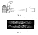
- FIG. 3 depicts a solid state laser system in accordance with another alternate embodiment of the present invention.
- FIG. 4 is a graphical reproduction of an interferogram showing the effect of optical path differences before (upper view) and after (lower view) compensation in accordance with the present invention.
- the present invention is concerned with techniques for reducing thermo-optic distortions In high power solid state lasers.
- Scaling of slab lasers to high powers has been limited, as a practical matter, by an inability to obtain high power outputs with a desirably high beam quality because thermal non-uniformities in the slab produce optical path differences (OPD) across the slab aperture and these differences have a negative impact on beam quality.
- OPD optical path differences
- Control of the thermal profile of the slab by means of tailored cooling or tailored edge heat deposition has not provided a satisfactory solution to the OPD problem.
- FIGS. 1A and 1B depict one implementation of the invention.
- FIG. 1A is a side view and FIG 1B is a top view, respectively, of a laser that includes a slab 10 of solid state lasing material, such as rare earth doped yttrium-aluminum-garnet (YAG).
- YAG rare earth doped yttrium-aluminum-garnet
- a main diode array 12 has its output directed into one end of the slab 10.
- This pump energy may, as in the system of Patent No.6,094,297, be reflected from an end facet of the slab 10, and there may be an additional diode array (not shown) launching pump energy into the other end facet of the slab.
- At least one input light beam 14 is also launched into an end facet of the slab 10, as indicated in FIG. 1B, this input light beam is amplified in the slab 10 and emerges from an aperture formed by the opposite end facet.
- the amplified beam may, in some applications, make multiple passes through the gain medium of the slab.
- the slab 10 is subject to variations in temperature and these thermal variations give rise to optical distortions. It is of critical importance to beam quality obtained from the laser that the optical path differences (OPD) across the clear aperture of the slab 10 be kept below or close to a level of approximately 1 micron per pass through the slab. OPDs of this order of magnitude are correctable using conventional techniques of phase conjugation and adaptive optics. Urihilst, as slab lasers of this type are scaled up in power the OPDs are more typically on the order of 10 microns per pass. Therefore, this thermo-optic OPD phenomenon effectively limits the beam quality obtainable from solid state lasers.
- OPD optical path differences
- the OPD profile across the clear aperture of the laser slab 10 is tailored to be more uniform.
- One approach to tailoring the OPD profile is illustrated in FIGS. 1A and 1B and includes the use of an auxiliary diode array 16.
- Outputs from the auxiliary array 16 are focused by lenses 18, 20, 22 and 24 and then launched into an end facet of the slab 10.
- FIG. 1A light from diodes of the auxiliary array 16 is focused and then condensed before launching into the slab 10 as a set of generally parallel beams.
- FIG. 1B as viewed along an orthogonal axis, the same optical outputs from auxiliary array 16 are focused into a narrower beam for launching into the inclined end facet of the slab 10.
- the slab 10 is relatively thin in one dimension, for example approximately 2 mm in thickness, but may be as wide as, for example, 20 mm in the orthogonal direction.
- the auxiliary array 16 is a 25-bar array, only four bars of which are shown in FIG. 1A. Output from the array 16 is image relayed in the fast axis (as shown in FiG. 1A) onto the end facet of the slab 10, to fill the 20-mm slab clear aperture. In effect, each bar of the auxiliary array 16 may be thought of as being mapped into a corresponding portion of the slab aperture.
- FIGS. 1A and 1B also includes a beam blocker 30, in the form or at least one rod lens that is movable to block light from one or more of the diode bars of the auxiliary array 16.
- the beam blocker 30 in this embodiment does not actually block light from the array 16 but deflects it such that much less light from the affected portion of the array reaches the slab 10.
- the beam blocker 30 can be moved to a location that "blocks" (deflects) light from a selected bar or bars of the auxiliary array 16, thereby modulating light from the auxiliary array 16.
- the function of the modulated auxiliary array 16 is to introduce OPD selectively into the slab 10, effectively to cancel OPD induced by the main pump arrays 12 or by other components in the laser system.
- FIGS. 2A and 2B depict an embodiment similar to that shown in FIGS. 1A and 1B, except that there is no beam blocker 30 in FIGS. 2A and 2B.
- each diode bar in the auxiliary array 16 is coupled to individual auxiliary diode controls 32, which allow the individual diode bars of the auxiliary array 16 to be separately modulated.
- each bar in the auxiliary array 16 can be modulated to emit a greater or lesser optical power than the other bars In the array.
- the effect, as in the FIGS. 1A and 1B embodiment, is to provide OPD control over individual sections of the slab 10, and to effect compensation for OPD caused by the main diode array 12.
- the auxiliary pump array 16 may consist of an array of fiber-coupled lasers or laser diodes arranged in an equivalent manner to deposit power In spatially localized regions in the slab.
- the use of fiber-coupled auxiliary pumps has some advantages in that the high beam quality obtainable from commerically available fiber-coupled laser diodes can eliminate the need for imaging lenses 18, 20, 22, 24, which reduces volume and simplifies the design, assembly, and parts count.
- the auxiliary diode controls 32 are adjusted in accordance with information obtained from OPD measurements 34.
- these OPD measurements may be taken at the output facet of the slab 10, using conventional interferometric techniques.
- a probe beam having a frequency or angle of incidence different from that of the input beam 14 may also be input to the slab 10, and then output from the slab and compared with a reference beam of the same frequency as the probe beam.
- the probe beam is subject to the same OPD effects as the amplified beam as it is propagated through the slab, and these OPD effects are quantified when the output probe beam is compared with the reference beam.
- the output probe beam and the reference beam are directed onto an optical sensor that produces an interferogram similar to that shown in FIG. 4.
- the upper view in FIG. 4 indicates significant OPD effects across the slab aperture, which is represented by the bright rectangular window in the drawing.
- the irregular and wavy lines in the fringe pattern of the interferogram indicate OPD variations across the aperture.
- the lower view in FIG. 4 depicts the same interference pattern after compensation by modulation of the auxiliary light input profile.
- the wavy lines in the lower pattern have been rendered nearly parallel by the technique of the invention.
- OPD information can also be obtained by measuring a low-power sample of the main amplified beam itself. This measurement can be performed by generating a low-power replica of the amplified beam following traversal through the gain medium, typically by reflection from an uncoated or anti-reflective coated surface placed in the amplified beam path. The OPD of the low power replica can then be measured as above by interference with a phase-coherent reference beam, or via some other means of wavefront detection (e.g., a Shack-Hartmann wavefront sensor). This alternative means of recording OPD information eliminates the need for an independent probe beam, since the amplified laser beam acts as its own probe.
- the measured OPD will be the net sum of all the OPD imposed on the amplified beam by every element in its path, e.g. other gain modules, mirrors, lenses, etc.
- These measurements provide information that can determine an appropriate conjugate OPD to impose via trim pumping onto the gain module such that the net measured OPD of the amplified beam at the output of the laser system is reduced to near zero, thus achieving higher beam quality and brightness.
- the line 36 in FIG. 2A implies that there is a feedback loop whereby OPD measurements are fed back to control the auxiliary diode array 16, it should be understood that this feedback of information may take various forms.
- the invention operates without continuous feedback and adjustment of the auxiliary diode array 16. Based on only occasional observations of the OPD variations across the aperture of the slab 10, the auxiliary diode controls 32 (FIG. 2A) or the beam blocker(s) 30 (FIG. 1A) are adjusted to perform OPD compensation.
- OPD measurements may be taken on a continuous or periodic basis and fed back over line 36 to control individual diode bars in the auxiliary array 16 to provide continually adjusted compensation of the OPD profile of the slab 10.
- FiG. 3 shows an embodiment of the invention in which one array module 40.2 of an array module stack 40 is modulated to compensate for OPD effects in a laser slab 10.
- Three diode array modules 40.1, 40.2 and 40.3 all contribute light output to pump the gain medium slab 10 through an end face.
- the module stack 40 is the "main" diode module of the laser.
- the outputs from the array stack 40 are coupled through array optics 42 for launching into the end face of the slab 10.
- the center array 40.2 of the stack 40 is subject to blocking by a selective beam block module 44.
- This may, for example, take the form of an array of stripped optical fibers, each of which can function to deflect light from one or more of the laser bars in the array 40.2, thereby modulating the diode pump light impinging on the slab 10.
- light from the array 40.2 is modulated to compensate for OPD effects in the slab 10, caused by various other factors.
- FIG. 3 the distinction between a "main" diode array and an "auxiliary" diode array, although useful for purposes of explanation of the FIGS. 1 and 2 embodiments, is not a particularly useful one in this embodiment of the invention.
- the common feature of the various embodiments of present invention is the ability to modulate or spatially contour light from a diode array, to produce an OPD effect that compensates for OPD arising from other causes. This modulation may be effected in an auxiliary diode array or in a main diode array.
- the present invention represents a significant advance in solid state lasers.
- the invention enables higher powers and brightness levels to be achieved by compensating for OPD effects in the laser gain medium.
- the invention has been described in detail for purposes of illustration, various modifications may be made without departing from the spirit and scope of the invention.
- the invention has been described in terms of its application to a slab laser, the principles of the invention may also be applied to other diode pumped solid state laser architectures, including rods, thin disks and one-dimensional waveguides. Accordingly, the invention should not be limited except as by the accompanying claims.
Landscapes
- Physics & Mathematics (AREA)
- Electromagnetism (AREA)
- Engineering & Computer Science (AREA)
- Plasma & Fusion (AREA)
- Optics & Photonics (AREA)
- Chemical & Material Sciences (AREA)
- Crystallography & Structural Chemistry (AREA)
- Lasers (AREA)
Applications Claiming Priority (1)
| Application Number | Priority Date | Filing Date | Title |
|---|---|---|---|
| US11/094,734 US20060227822A1 (en) | 2005-03-29 | 2005-03-29 | Laser trim pump |
Publications (1)
| Publication Number | Publication Date |
|---|---|
| EP1708320A1 true EP1708320A1 (fr) | 2006-10-04 |
Family
ID=36052675
Family Applications (1)
| Application Number | Title | Priority Date | Filing Date |
|---|---|---|---|
| EP06075111A Withdrawn EP1708320A1 (fr) | 2005-03-29 | 2006-01-17 | Source de pompage pour l'accord d'un laser |
Country Status (2)
| Country | Link |
|---|---|
| US (1) | US20060227822A1 (fr) |
| EP (1) | EP1708320A1 (fr) |
Cited By (3)
| Publication number | Priority date | Publication date | Assignee | Title |
|---|---|---|---|---|
| WO2012055625A1 (fr) * | 2010-10-28 | 2012-05-03 | Robert Bosch Gmbh | Bougie d'allumage laser et son procédé de fonctionnement |
| WO2014154193A1 (fr) * | 2013-03-25 | 2014-10-02 | Friedrich-Schiller-Universität Jena | Procédé et dispositif de pompage optique d'amplificateurs laser afin de générer un rayonnement laser ayant des propriétés de faisceau définies |
| WO2023160852A1 (fr) * | 2022-02-25 | 2023-08-31 | Trumpf Laser Gmbh | Système laser avec un amplificateur multipasse configuré pour la conservation de la charge thermique |
Families Citing this family (3)
| Publication number | Priority date | Publication date | Assignee | Title |
|---|---|---|---|---|
| US7822091B2 (en) * | 2008-07-14 | 2010-10-26 | Lockheed Martin Corporation | Inverted composite slab sandwich laser gain medium |
| US9496675B1 (en) * | 2013-07-09 | 2016-11-15 | Science Research Laboratory, Inc. | Method and reflective apparatus for combining high-power laser beams |
| CN119787075B (zh) * | 2025-03-10 | 2025-08-12 | 中国科学院长春光学精密机械与物理研究所 | 一种热焦距可控的泵浦模块、激光器和激光放大器 |
Citations (3)
| Publication number | Priority date | Publication date | Assignee | Title |
|---|---|---|---|---|
| US5926494A (en) * | 1997-04-11 | 1999-07-20 | Hughes Electronics Corporation | Laser systems with improved performance and reduced parasitics and method |
| EP1160940A1 (fr) * | 2000-05-30 | 2001-12-05 | TRW Inc. | Amplificateur optique comprenant un matériaux de gain en plaque zig-zag pompé longitudinalement |
| WO2003085446A2 (fr) * | 2002-04-04 | 2003-10-16 | Lzh Laserzentrum Hannover E.V. | Dispositif amplificateur d'impulsions laser courtes, notamment ultracourtes |
Family Cites Families (6)
| Publication number | Priority date | Publication date | Assignee | Title |
|---|---|---|---|---|
| JPH06334262A (ja) * | 1993-03-23 | 1994-12-02 | Mitsubishi Electric Corp | 半導体レーザアレイ装置,半導体レーザ装置,及びそれらの製造方法 |
| US6873639B2 (en) * | 1993-05-28 | 2005-03-29 | Tong Zhang | Multipass geometry and constructions for diode-pumped solid-state lasers and fiber lasers, and for optical amplifier and detector |
| US6075912A (en) * | 1998-03-17 | 2000-06-13 | Polaroid Corporation | Apparatus for coupling radiation beams into an optical waveguide |
| US6441367B1 (en) * | 1999-06-02 | 2002-08-27 | Mitutoyo Corporation | Control systems and methods for diffuse illumination |
| CA2335529A1 (fr) * | 1999-04-20 | 2000-10-26 | Yuichiro Irie | Module a diode laser |
| EP1560304B1 (fr) * | 2003-03-13 | 2012-01-11 | Fujitsu Limited | Amplificateur optique avec une fonction de contrôle du signal de pompe et un système de transmission optique utilisant le dit amplificateur |
-
2005
- 2005-03-29 US US11/094,734 patent/US20060227822A1/en not_active Abandoned
-
2006
- 2006-01-17 EP EP06075111A patent/EP1708320A1/fr not_active Withdrawn
Patent Citations (3)
| Publication number | Priority date | Publication date | Assignee | Title |
|---|---|---|---|---|
| US5926494A (en) * | 1997-04-11 | 1999-07-20 | Hughes Electronics Corporation | Laser systems with improved performance and reduced parasitics and method |
| EP1160940A1 (fr) * | 2000-05-30 | 2001-12-05 | TRW Inc. | Amplificateur optique comprenant un matériaux de gain en plaque zig-zag pompé longitudinalement |
| WO2003085446A2 (fr) * | 2002-04-04 | 2003-10-16 | Lzh Laserzentrum Hannover E.V. | Dispositif amplificateur d'impulsions laser courtes, notamment ultracourtes |
Non-Patent Citations (1)
| Title |
|---|
| HARKNESS G K; OPPO G -L; MARTIN R; SCROGGIE A J; FIRTH W J: "Elimination of spatiotemporal disorder by Fourier space techniques", PHYSICAL REVIEW A, vol. 58, no. 3, September 1998 (1998-09-01), USA, pages 2577 - 2586, XP002374763 * |
Cited By (3)
| Publication number | Priority date | Publication date | Assignee | Title |
|---|---|---|---|---|
| WO2012055625A1 (fr) * | 2010-10-28 | 2012-05-03 | Robert Bosch Gmbh | Bougie d'allumage laser et son procédé de fonctionnement |
| WO2014154193A1 (fr) * | 2013-03-25 | 2014-10-02 | Friedrich-Schiller-Universität Jena | Procédé et dispositif de pompage optique d'amplificateurs laser afin de générer un rayonnement laser ayant des propriétés de faisceau définies |
| WO2023160852A1 (fr) * | 2022-02-25 | 2023-08-31 | Trumpf Laser Gmbh | Système laser avec un amplificateur multipasse configuré pour la conservation de la charge thermique |
Also Published As
| Publication number | Publication date |
|---|---|
| US20060227822A1 (en) | 2006-10-12 |
Similar Documents
| Publication | Publication Date | Title |
|---|---|---|
| US6809307B2 (en) | System and method for effecting high-power beam control with adaptive optics in low power beam path | |
| US5166818A (en) | Optical pulse-shaping device and method, and optical communications station and method | |
| JP6807897B2 (ja) | レーザのスペクトル帯域幅の低減 | |
| JP2004515052A (ja) | 干渉性ファイバアンプアレイの位相制御機構 | |
| US9502854B1 (en) | Self-seeding high power laser | |
| JP6637615B2 (ja) | 高出力レーザのための2軸適応光学(ao)システム | |
| US20100002743A1 (en) | Laser focusing through turbulent medium | |
| GB2275347A (en) | Optical waveguide grating formed by transverse optical exposure | |
| Van Wonterghem et al. | Beamlet pulse-generation and wavefront-control system | |
| EP1708320A1 (fr) | Source de pompage pour l'accord d'un laser | |
| US20050147141A1 (en) | Methods and devices for forming a high-power coherent light beam | |
| EP0452838A1 (fr) | Dispositif de conjugaison de phase optique avec guide de lumière pour combinaison de plusieurs rayons lumineux | |
| US12266898B2 (en) | Methods and devices for laser power projection on a remote target with coherent fiber array and adaptive beam control | |
| CN118011628A (zh) | 一种基于同口径收发及主动照明的阵列激光大气像差补偿装置 | |
| US5506860A (en) | Etalon and single-longitudinal-mode laser using the same | |
| JPH0256518A (ja) | 画像走査記録装置 | |
| US11349271B2 (en) | Fixed bulk compressor for use in a chirped pulse amplification system | |
| Jones et al. | A multi-channel phase locked fibre bundle laser | |
| US8811437B2 (en) | Laser device with phase front regulation | |
| EP2206011B1 (fr) | Source laser comportant un dispositif de balayage angulaire | |
| US5930282A (en) | Method and apparatus for adjusting the pump distribution in a laser | |
| EP0519078A1 (fr) | Generateur de faisceaux laser | |
| Omori et al. | Tunable light source with GaN-based violet laser diode | |
| EP3823111B1 (fr) | Procédé pour amplifier un faisceau laser, système amplificateur de laser et module optique destiné à être utilisé dans un système amplificateur de laser | |
| US4945315A (en) | Method of and apparataus for projecting a laser beam into light amplifier |
Legal Events
| Date | Code | Title | Description |
|---|---|---|---|
| PUAI | Public reference made under article 153(3) epc to a published international application that has entered the european phase |
Free format text: ORIGINAL CODE: 0009012 |
|
| AK | Designated contracting states |
Kind code of ref document: A1 Designated state(s): AT BE BG CH CY CZ DE DK EE ES FI FR GB GR HU IE IS IT LI LT LU LV MC NL PL PT RO SE SI SK TR |
|
| AX | Request for extension of the european patent |
Extension state: AL BA HR MK YU |
|
| 17P | Request for examination filed |
Effective date: 20070403 |
|
| 17Q | First examination report despatched |
Effective date: 20070507 |
|
| AKX | Designation fees paid |
Designated state(s): DE FR GB |
|
| GRAP | Despatch of communication of intention to grant a patent |
Free format text: ORIGINAL CODE: EPIDOSNIGR1 |
|
| STAA | Information on the status of an ep patent application or granted ep patent |
Free format text: STATUS: THE APPLICATION IS DEEMED TO BE WITHDRAWN |
|
| 18D | Application deemed to be withdrawn |
Effective date: 20081127 |