EP1708341A2 - Anlage und Verfahren zur Magnetisierung der Dauermagnetrotoren der elektrischen Maschinen - Google Patents
Anlage und Verfahren zur Magnetisierung der Dauermagnetrotoren der elektrischen Maschinen Download PDFInfo
- Publication number
- EP1708341A2 EP1708341A2 EP06251569A EP06251569A EP1708341A2 EP 1708341 A2 EP1708341 A2 EP 1708341A2 EP 06251569 A EP06251569 A EP 06251569A EP 06251569 A EP06251569 A EP 06251569A EP 1708341 A2 EP1708341 A2 EP 1708341A2
- Authority
- EP
- European Patent Office
- Prior art keywords
- rotor
- permanent magnet
- magnet segments
- orientation directions
- magnetization
- Prior art date
- Legal status (The legal status is an assumption and is not a legal conclusion. Google has not performed a legal analysis and makes no representation as to the accuracy of the status listed.)
- Withdrawn
Links
- 238000000034 method Methods 0.000 title claims abstract description 52
- 230000005415 magnetization Effects 0.000 title claims abstract description 28
- 230000004907 flux Effects 0.000 claims abstract description 26
- 238000004519 manufacturing process Methods 0.000 claims abstract description 8
- 230000005291 magnetic effect Effects 0.000 claims description 21
- 230000001360 synchronised effect Effects 0.000 claims description 3
- 238000009826 distribution Methods 0.000 description 8
- 230000005534 acoustic noise Effects 0.000 description 2
- 239000000463 material Substances 0.000 description 2
- 238000012986 modification Methods 0.000 description 2
- 230000004048 modification Effects 0.000 description 2
- 230000005405 multipole Effects 0.000 description 2
- 238000004804 winding Methods 0.000 description 2
- 229920000049 Carbon (fiber) Polymers 0.000 description 1
- 229910000831 Steel Inorganic materials 0.000 description 1
- 239000004917 carbon fiber Substances 0.000 description 1
- 230000000052 comparative effect Effects 0.000 description 1
- 238000005520 cutting process Methods 0.000 description 1
- 230000001419 dependent effect Effects 0.000 description 1
- 239000003302 ferromagnetic material Substances 0.000 description 1
- 239000002184 metal Substances 0.000 description 1
- 239000000203 mixture Substances 0.000 description 1
- 229910001172 neodymium magnet Inorganic materials 0.000 description 1
- 239000003973 paint Substances 0.000 description 1
- 238000000926 separation method Methods 0.000 description 1
- 239000010959 steel Substances 0.000 description 1
- 229910000859 α-Fe Inorganic materials 0.000 description 1
Images


Classifications
-
- H—ELECTRICITY
- H02—GENERATION; CONVERSION OR DISTRIBUTION OF ELECTRIC POWER
- H02K—DYNAMO-ELECTRIC MACHINES
- H02K15/00—Processes or apparatus specially adapted for manufacturing, assembling, maintaining or repairing of dynamo-electric machines
- H02K15/02—Processes or apparatus specially adapted for manufacturing, assembling, maintaining or repairing of dynamo-electric machines of stator or rotor bodies
- H02K15/03—Processes or apparatus specially adapted for manufacturing, assembling, maintaining or repairing of dynamo-electric machines of stator or rotor bodies having permanent magnets
-
- H—ELECTRICITY
- H02—GENERATION; CONVERSION OR DISTRIBUTION OF ELECTRIC POWER
- H02K—DYNAMO-ELECTRIC MACHINES
- H02K1/00—Details of the magnetic circuit
- H02K1/06—Details of the magnetic circuit characterised by the shape, form or construction
- H02K1/22—Rotating parts of the magnetic circuit
- H02K1/27—Rotor cores with permanent magnets
- H02K1/2706—Inner rotors
- H02K1/272—Inner rotors the magnetisation axis of the magnets being perpendicular to the rotor axis
- H02K1/274—Inner rotors the magnetisation axis of the magnets being perpendicular to the rotor axis the rotor consisting of two or more circumferentially positioned magnets
- H02K1/2753—Inner rotors the magnetisation axis of the magnets being perpendicular to the rotor axis the rotor consisting of two or more circumferentially positioned magnets the rotor consisting of magnets or groups of magnets arranged with alternating polarity
- H02K1/278—Surface mounted magnets; Inset magnets
-
- Y—GENERAL TAGGING OF NEW TECHNOLOGICAL DEVELOPMENTS; GENERAL TAGGING OF CROSS-SECTIONAL TECHNOLOGIES SPANNING OVER SEVERAL SECTIONS OF THE IPC; TECHNICAL SUBJECTS COVERED BY FORMER USPC CROSS-REFERENCE ART COLLECTIONS [XRACs] AND DIGESTS
- Y10—TECHNICAL SUBJECTS COVERED BY FORMER USPC
- Y10T—TECHNICAL SUBJECTS COVERED BY FORMER US CLASSIFICATION
- Y10T29/00—Metal working
- Y10T29/49—Method of mechanical manufacture
- Y10T29/49002—Electrical device making
- Y10T29/49009—Dynamoelectric machine
- Y10T29/49012—Rotor
Definitions
- the invention relates generally to electrical machines, particularly to electrical machines having permanent magnet type rotors.
- Specific embodiments of the present technique relate to a system and method for magnetization of permanent magnet segments in such rotors.
- An electrical machine such as a motor or a generator, generally includes a rotor disposed within a stator and utilized to convert electrical power to mechanical power or vice versa.
- Certain electrical machines use permanent magnet type rotors, which reduce the size and enhance the overall efficiency of the machine.
- a rotor generally includes an annular permanent magnet, disposed over a rotor spindle.
- the permanent magnet is a monolithic, hollow, cylindrical member.
- the permanent magnet is generally formed by assembling a plurality of permanent magnets assembled around a rotor spindle.
- High speed electrical machines may also include a holding ring or a retaining ring around the permanent magnet assembly to prevent fracturing and scattering of the permanent magnet assembly by centrifugal forces.
- the permanent magnet segments are magnetized prior to assembly on the rotor spindle.
- the permanent magnet segments are cut and ground to shape from larger unfinished magnet blocks, after which the segments are magnetized individually in a solenoid coil.
- magnetization of the permanent magnet segments is achieved via a magnetization vector proposed by K. Halbach (also known as Halbach magnetization), which, when applied to the surface of the permanent magnets, results in a more sinusoidal shaped flux distribution within the electrical machine, thereby reducing AC harmonic losses and reducing torque ripple, vibration and acoustic noise.
- the permanent magnet segments are subsequently adhesively bonded to the rotor spindle.
- assembly of the rotor from pre-magnetized permanent magnet segments may be a cumbersome process, especially in larger electrical machines, as it may be time consuming and unwieldly.
- the process can involve substantial forcing and aligning by mechanical devices to position and restrain the energized permanent magnet segments.
- the process is prone to physical accidents if energized permanent magnet blocks escape restraint.
- a method of manufacturing an electrical machine includes assembling an array of permanent magnet segments around a rotor spindle of the electrical machine. Desired orientation directions are determined for the permanent magnet segments. The method further includes positioning the assembled permanent magnet segments in a magnetization fixture such that the desired orientation directions of the permanent magnet segments are aligned with corresponding flux directions of the magnetizing fixture.
- the present technique provides a system and method for magnetizing permanent magnet segments in an electrical machine rotor.
- each pole of the rotor magnet comprises a Halbach array of permanent magnet segments.
- the present technique provides for a one-step magnetization of an entire assembled rotor in a multipole magnetizing fixture, in such a manner as to obtain optimal magnetization of the oriented magnets. Specific embodiments of the present technique are illustrated hereinafter with reference to FIGS. 1-6.
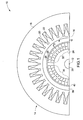
- FIG. 1 there is illustrated an exemplary portion of an electrical machine 10, wherein aspects of the present technique are incorporated.
- the electrical machine 10 may include, for example a polyphase synchronous electrical motor or generator.
- FIG. 1 shows a cross-sectional view taken in direction perpendicular to a rotary axis of 12 the electrical machine 10.
- the electrical machine 10 comprises a stator 14 and a rotor 16.
- the stator 14 includes a laminated stator core 18, generally formed from electromagnetic steel sheets. Slots 20 are formed on the stator core 18 to accommodate stator windings 22.
- the rotor 16 is disposed within the stator 14 so as to permit rotation around the rotary axis 12 while being supported by bearings (not shown).
- the rotor 16 includes a rotor spindle 24 mounted on a shaft 26.
- the shaft 26 may be formed integral to the rotor spindle 24.
- the rotor spindle 24 and the shaft 26 are formed from a ferromagnetic material.
- the rotor 16 of the illustrated embodiment is a permanent magnet type rotor including an annular array of permanent magnet segments 28 disposed over the rotor spindle 24.
- the arrows 29 illustrate the unique orientation direction of each of the permanent magnet segments 28.
- the orientation direction is the direction that a permanent magnet obtains its strongest magnetization, and it is imparted to the magnet segments during its manufacture as individual segments.
- Cross-sectional shapes of the permanent magnet segments 28 may include an arcuate shape, as illustrated in FIG. 1, or may include other suitable shapes, such as a generally trapezoidal, polygonal or a triangular shape.
- the permanent magnet segments 28 may be formed from any ferrite series, NdFeB series, Sm-Co series, SmFeN series, among any others that possess an oriented characteristic.
- the orientation of a permanent magnet material is created by applying a magnetic field while the material is pressed in a soft, wet condition.
- the orientation of shaped segment may be established by orienting a shaped press mold to the applied magnetic field, or by cutting the shaped segment appropriately from a larger finished block of known orientation direction.
- the permanent magnet segments 28 may be adhesively bonded or sintered to the rotor spindle 24.
- the rotor 16 includes four poles 30, 32, 34, 36 (34 and 36 not shown in FIG. 1), each pole being constituted by eight permanent magnet segments 28.
- a retaining ring 38 is disposed around the permanent magnet segments 28 to secure the permanent magnet segments 28 against centrifugal forces caused by rotation of the rotor 16.
- Retaining ring 38 may be formed from carbon fibers or from a high-strength metal.
- An electromagnetic shield 40 may be desirable in arrangements in which the retaining ring 32 has a non-metallic composition.
- the permanent magnet segments 28 of the rotor 16 form a Halbach array (i.e. obtained by Halbach magnetization discussed above) to produce a more sinusoidal shaped flux distribution within the electrical machine 10. This reduces AC harmonic losses, resulting in consequently reduced torque ripple, vibration and acoustic noise.
- each permanent magnet segment 28 is such that the direction 29 is nearly tangential to the direction of rotation of the rotor at a quadrature axis (hereinafter referred to as a Q-axis) of each rotor pole 30, 32, 34 and 36, and is nearly normal to the rotation direction at a direct axis (hereinafter referred to as a D-axis) of each of the rotor poles 30, 32, 34 and 36.
- the D-axis may be defined as the location in a magnetic pole wherein the magnetic field is most strongly radially directed, and whereas the Q-axis generally corresponds to the location in the magnetic pole wherein the magnetic field is most strongly peripherally directed.
- the Q and D axes of a magnetic pole differ electrically by 90 degrees, their relative physical locations depend on the geometry and number of poles of the rotor. For example, in a four-pole rotor, the Q and D axes of each pole are angularly separated by about 45 degrees.
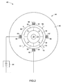
- FIG. 2 illustrates a magnetization apparatus 42 in accordance with aspects of the present technique.
- the magnetization apparatus 42 includes a multipole magnetizing fixture 44 within which the rotor 16 is securely positioned for magnetization of the permanent magnet segments 28 (FIG. 1).
- the magnetizing fixture 44 comprises magnetizing coils wound around a magnetizer core or yoke 46.
- the number of magnetizing coils is generally chosen to be equal to the number of poles of the rotor. Accordingly, in the illustrated embodiment, the fixture 44 includes four coils 48, 50, 52 and 54 accommodated in slots 56, 58, 60 and 62 provided on the magnetizer core 46.
- the rotor 16 is positioned within the fixture 44 in such a way that the Q axes of the rotor poles 30, 32, 34 and 36 are aligned with the magnetizing coils 48, 50, 52 and 54 respectively.
- the coils 48, 50, 52 and 54 are energized by a power source 64.
- the power source 64 is desirably a pulsed DC power source in order to reduce the duration of current flowing through the coils.
- the coils 48, 50, 52 and 54 may be coupled to the power source 64 in series, as illustrated in FIG. 2, or in parallel.
- the magnetizing coils 48, 50, 52 and 54 When energized, the magnetizing coils 48, 50, 52 and 54 produce a magnetic flux through magnetizer poles 66, 68, 70, 72, the centers (or D-axes) of which are coincident with the D-axes of the rotor poles 30, 32, 34 and 36, and through the permanent magnet segments 28.
- the orientations 29 of the magnet segments 28 are determined a priori by magnetic analysis, such as by finite element method.
- the orientations are located with respect to the segment physical shape during manufacture of the permanent magnet segments. These orientations may be marked, for example by paint, on individual permanent magnet segments to facilitate the assembly process.
- FIG. 3 schematically illustrates the orientations 29 of the permanent magnet segments 28 with respect to the magnetic flux 74 of the magnetizing fixture 44, magnetic flux 74 being calculated by finite element method.
- FIG. 3 illustrates orientations for segments in the pole 30 of the rotor 16.
- the magnetization direction 29 for each segment 28 corresponds to a Halbach orientation as discussed above.
- the orientation directions 29 of the individual permanent magnet segments 28 are such as to be nearly coincident in direction with the magnetic flux 74 produced by the energized magnetizing coils. Further, as illustrated, the magnetic orientation of the permanent magnet segments are progressively swept from being nearly tangential at a rotor pole Q-axis 76 to being nearly normal at a rotor pole D-axis 78.
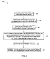
- FIG. 4 is a flowchart illustrating an exemplary process 80 for manufacturing an electrical machine in accordance with certain embodiments of the present technique.
- the process begins by assembling a rotor spindle around a shaft, as indicated at block 82.
- the shaft may be formed integral to the rotor spindle.
- the permanent magnet segments are assembled around the rotor spindle. In one embodiment, theses segments are adhesively bonded to each other and to the rotor spindle.
- a retaining ring may be disposed around the permanent magnet segments, as indicated at block 86.
- the process then proceeds at block 88 by positioning the rotor assembly within a magnetizing fixture.
- block 88 includes aligning magnetization directions of the permanent magnet segments with the direction of flux from the magnetizing fixture.
- the magnetizing coils are then energized by a power source, as indicated at bock 90.
- the rotor assembly is removed from the magnetizing fixture and is assembled within the stator (block 92).
- the process 80 may be implemented by a fully automated assembly line, semi-automatically, or even manually.
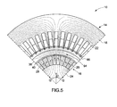
- FIG. 5 is an illustration of exemplary flux distribution in the resulting magnetized rotor 16.
- the permanent magnet segments produce a magnetic flux 94, which is linked to the stator core 18 to produce rotational torque on the rotor 16. Torque produced on the rotor is dependent, among other factors, on the shape of the flux distribution at an air gap 96 between the stator 14 and the rotor 16.
- the flux 94 produced by the magnetized rotor is oriented along the magnetization direction of the permanent magnet segments 28, which varies from being generally tangential at the rotor pole Q-axes to being generally normal at the rotor pole D-axis.
- the flux density i.e.
- FIG. 6 shows the variation flux density (in Tesla) in the air gap 96, represented along a Y-axis, with position of the rotor (in electrical coordinates), represented along an X-axis.
- the electrical coordinates are represented as a fraction of 180 electrical degrees, which, in the illustrated embodiment corresponds to an angular separation of 180 degrees.
- the flux density distribution of a Halbach magnetized rotor is substantially more sinusoidal as compared to that of a radially magnetized rotor.
- the present technique may thus facilitate magnetization of a electrical machine rotor in a one-step process, thus obviating the need to assemble the rotor from pre-magnetized blocks, which may be cumbersome and difficult as discussed earlier.
- the resulting magnetized rotor produces a more sinusoidally shaped flux distribution within the electric machine.
- the present technique can be incorporated in a wide range of electrical machinery, including motors, and particularly including large high-speed synchronous machines for gas line compressors, aerospace motors, aerospace generators, marine propulsion motors, among others.
Landscapes
- Engineering & Computer Science (AREA)
- Power Engineering (AREA)
- Manufacturing & Machinery (AREA)
- Permanent Field Magnets Of Synchronous Machinery (AREA)
- Manufacture Of Motors, Generators (AREA)
Applications Claiming Priority (1)
| Application Number | Priority Date | Filing Date | Title |
|---|---|---|---|
| US11/094,910 US7228616B2 (en) | 2005-03-31 | 2005-03-31 | System and method for magnetization of permanent magnet rotors in electrical machines |
Publications (2)
| Publication Number | Publication Date |
|---|---|
| EP1708341A2 true EP1708341A2 (de) | 2006-10-04 |
| EP1708341A3 EP1708341A3 (de) | 2010-03-10 |
Family
ID=36202419
Family Applications (1)
| Application Number | Title | Priority Date | Filing Date |
|---|---|---|---|
| EP06251569A Withdrawn EP1708341A3 (de) | 2005-03-31 | 2006-03-23 | Anlage und Verfahren zur Magnetisierung der Dauermagnetrotoren der elektrischen Maschinen |
Country Status (5)
| Country | Link |
|---|---|
| US (1) | US7228616B2 (de) |
| EP (1) | EP1708341A3 (de) |
| JP (1) | JP2006288193A (de) |
| CN (1) | CN1866688B (de) |
| RU (1) | RU2412516C2 (de) |
Cited By (5)
| Publication number | Priority date | Publication date | Assignee | Title |
|---|---|---|---|---|
| EP2299112A3 (de) * | 2007-03-23 | 2013-06-19 | Vestas Wind Systems A/S | Verfahren zur Herstellung eines Windturbinengenerators mit einem oder mehreren Permanentmagnetrotoren, Windturbinengondel und Windturbine |
| EP2312732A3 (de) * | 2009-10-19 | 2017-03-08 | General Electric Company | Magnetisierung der entmagnetisierten Dauermagnet-segmenten einer elektrischen Maschinen |
| EP2573917B1 (de) * | 2011-09-20 | 2019-09-25 | Shinano Kenshi Kabushiki Kaisha | Verfahren zur Herstellung eines Rotors und eines bürstenlosen Innenrotormotors |
| US20220254557A1 (en) * | 2019-12-31 | 2022-08-11 | Baker Hughes Oilfield Operations Llc | Systems and methods for magnetizing permanent magnet rotors |
| IT202100029243A1 (it) | 2021-11-18 | 2023-05-18 | Laboratorio Elettrofisico Eng S R L | Apparecchiatura di magnetizzazione halbach arrays |
Families Citing this family (26)
| Publication number | Priority date | Publication date | Assignee | Title |
|---|---|---|---|---|
| JP4588540B2 (ja) * | 2005-05-31 | 2010-12-01 | ニスカ株式会社 | マグネットロータの製造方法及びこの製法で作られたマグネットロータとこのマグネットロータを用いた電磁駆動装置並びに光量調整装置 |
| US7710081B2 (en) | 2006-10-27 | 2010-05-04 | Direct Drive Systems, Inc. | Electromechanical energy conversion systems |
| US8044547B2 (en) * | 2006-11-27 | 2011-10-25 | Panasonic Corporation | Radial-direction gap type magnet motor |
| US20090009012A1 (en) | 2007-07-03 | 2009-01-08 | General Electric Company | Assembly and method for magnetization of permanent magnet rotors in electrical machines |
| WO2009017430A1 (en) * | 2007-08-01 | 2009-02-05 | Fisher & Paykel Appliances Limited | Improved appliance, rotor and magnet element |
| US8253298B2 (en) | 2008-07-28 | 2012-08-28 | Direct Drive Systems, Inc. | Slot configuration of an electric machine |
| US8294316B2 (en) * | 2009-07-28 | 2012-10-23 | Rolls-Royce North American Technologies, Inc. | Electrical power generation apparatus for contra-rotating open-rotor aircraft propulsion system |
| JP5535827B2 (ja) * | 2010-08-24 | 2014-07-02 | アスモ株式会社 | ハルバッハ配列磁石の製造方法 |
| US8446121B1 (en) | 2010-11-19 | 2013-05-21 | The Boeing Company | High performance actuator motor |
| DE102010062316A1 (de) * | 2010-12-02 | 2012-06-06 | Siemens Aktiengesellschaft | Vorrichtung zur Positionsermittlung |
| DK2515417T3 (da) * | 2011-04-18 | 2014-05-05 | Siemens Ag | Synkron permanentmagnetmaskine |
| CN102195403B (zh) * | 2011-05-19 | 2013-04-24 | 乔鸣忠 | 一种大气隙低噪声机桨一体化永磁推进装置 |
| US9595851B2 (en) * | 2013-01-23 | 2017-03-14 | Mitsubishi Electric Corporation | Rotary electric machine |
| DE102013225093A1 (de) * | 2013-12-06 | 2015-06-11 | Siemens Aktiengesellschaft | Rotor für eine elektrische Maschine |
| CN104319060B (zh) * | 2014-09-17 | 2016-08-24 | 徐州通用高新磁电有限公司 | 一种永磁转子正弦充磁方法和装置 |
| KR101696710B1 (ko) * | 2015-01-28 | 2017-01-16 | 엘지전자 주식회사 | 비엘디시 모터 및 그를 갖는 청소기 |
| RU2604982C1 (ru) * | 2015-02-18 | 2016-12-20 | Общество с ограниченной ответственностью "ДЕГТЯРЕВ" | Устройство трехфазного асинхронного двигателя повышенной механической мощности |
| DE102016221291A1 (de) * | 2016-10-28 | 2018-05-03 | Volkswagen Aktiengesellschaft | Vorrichtung zum induktiven Erwärmen von mit einer Beschichtung versehenen Dauermagneten eines Rotors und/oder eines Klebers in Magnettaschen eines Rotors |
| US10518624B2 (en) * | 2017-06-15 | 2019-12-31 | Ford Global Technologies, Llc | Motor having non-rectangular rotor magnets |
| RU2646543C1 (ru) * | 2017-07-14 | 2018-03-06 | федеральное государственное бюджетное образовательное учреждение высшего образования "Уфимский государственный авиационный технический университет" | Магнитная система ротора с постоянными магнитами и способ ее изготовления |
| JP7302399B2 (ja) * | 2019-09-10 | 2023-07-04 | 株式会社デンソー | 回転電機の製造装置と回転電機の製造方法 |
| RU2718537C1 (ru) * | 2019-12-04 | 2020-04-08 | Андрей Борисович Захаренко | Способ намагничивания и сборки кольца Хальбаха ротора электромашины (варианты) |
| JP2021121153A (ja) * | 2020-01-30 | 2021-08-19 | 株式会社マグネイチャー | ハルバッハ界磁子およびこれを備える回転電機 |
| DE102021113775A1 (de) * | 2021-05-27 | 2022-12-01 | Rolls-Royce Deutschland Ltd & Co Kg | Permanentmagneterregte Synchronmaschine |
| JP7797956B2 (ja) | 2022-05-11 | 2026-01-14 | トヨタ自動車株式会社 | モータ |
| GB202305114D0 (en) * | 2023-04-06 | 2023-05-24 | Rolls Royce Plc | Magnetisation and demagnetisation of a component |
Citations (2)
| Publication number | Priority date | Publication date | Assignee | Title |
|---|---|---|---|---|
| JP2004072820A (ja) | 2002-08-01 | 2004-03-04 | Yaskawa Electric Corp | Acモータの回転子の着磁治具及びそれを用いた製造方法 |
| JP2005044820A (ja) * | 2002-06-18 | 2005-02-17 | Neomax Co Ltd | 極異方性リング磁石及びその製造方法 |
Family Cites Families (11)
| Publication number | Priority date | Publication date | Assignee | Title |
|---|---|---|---|---|
| JPS61125009A (ja) * | 1984-11-21 | 1986-06-12 | Hitachi Metals Ltd | 多極異方性円筒磁石の製造方法及び装置 |
| JPS6252913A (ja) * | 1985-09-02 | 1987-03-07 | Hitachi Metals Ltd | 多極異方性円筒状磁石の製造方法及び装置 |
| SU1704228A1 (ru) * | 1989-06-09 | 1992-01-07 | Н.В.Мартынов | Ротор электрической машины |
| RU2011267C1 (ru) * | 1991-07-08 | 1994-04-15 | Научно-Производственное Объединение "Магнетон" | Многополюсный ротор электрической машины с постоянными магнитами |
| JPH07212995A (ja) * | 1994-01-25 | 1995-08-11 | Fuji Electric Co Ltd | 逆突極性円筒型磁石同期電動機 |
| GB2299217B (en) * | 1995-03-23 | 1999-07-07 | Aisin Seiki | Method of assembling a permanent magnet rotor |
| US6542348B1 (en) * | 1998-02-03 | 2003-04-01 | Joseph J. Stupak, Jr. | Method and system for driving a magnetizing fixture |
| JP3889532B2 (ja) * | 1998-09-07 | 2007-03-07 | 三菱電機株式会社 | Dcブラシレスモータの組込着磁方法 |
| EP1333558A3 (de) * | 2002-01-31 | 2005-01-26 | Hitachi, Ltd. | Ankers einer elektrischen drehenden Maschine, Herstellungsverfahren derselben für Gasturbinenkraftwerk |
| JP4095334B2 (ja) * | 2002-04-26 | 2008-06-04 | キヤノン株式会社 | ステッピングモータ |
| DE102004017157B4 (de) * | 2004-04-07 | 2007-04-19 | Minebea Co., Ltd. | Verfahren zur Herstellung einer Rotoranordnung und Rotoranordnung für eine elektrische Maschine |
-
2005
- 2005-03-31 US US11/094,910 patent/US7228616B2/en not_active Expired - Lifetime
-
2006
- 2006-03-23 EP EP06251569A patent/EP1708341A3/de not_active Withdrawn
- 2006-03-29 JP JP2006090464A patent/JP2006288193A/ja active Pending
- 2006-03-30 RU RU2006110348/07A patent/RU2412516C2/ru active
- 2006-03-31 CN CN2006100793526A patent/CN1866688B/zh not_active Expired - Lifetime
Patent Citations (2)
| Publication number | Priority date | Publication date | Assignee | Title |
|---|---|---|---|---|
| JP2005044820A (ja) * | 2002-06-18 | 2005-02-17 | Neomax Co Ltd | 極異方性リング磁石及びその製造方法 |
| JP2004072820A (ja) | 2002-08-01 | 2004-03-04 | Yaskawa Electric Corp | Acモータの回転子の着磁治具及びそれを用いた製造方法 |
Cited By (6)
| Publication number | Priority date | Publication date | Assignee | Title |
|---|---|---|---|---|
| EP2299112A3 (de) * | 2007-03-23 | 2013-06-19 | Vestas Wind Systems A/S | Verfahren zur Herstellung eines Windturbinengenerators mit einem oder mehreren Permanentmagnetrotoren, Windturbinengondel und Windturbine |
| EP2312732A3 (de) * | 2009-10-19 | 2017-03-08 | General Electric Company | Magnetisierung der entmagnetisierten Dauermagnet-segmenten einer elektrischen Maschinen |
| EP2573917B1 (de) * | 2011-09-20 | 2019-09-25 | Shinano Kenshi Kabushiki Kaisha | Verfahren zur Herstellung eines Rotors und eines bürstenlosen Innenrotormotors |
| US20220254557A1 (en) * | 2019-12-31 | 2022-08-11 | Baker Hughes Oilfield Operations Llc | Systems and methods for magnetizing permanent magnet rotors |
| US12002610B2 (en) * | 2019-12-31 | 2024-06-04 | Baker Hughes Oilfield Operations Llc | Systems and methods for magnetizing permanent magnet rotors |
| IT202100029243A1 (it) | 2021-11-18 | 2023-05-18 | Laboratorio Elettrofisico Eng S R L | Apparecchiatura di magnetizzazione halbach arrays |
Also Published As
| Publication number | Publication date |
|---|---|
| CN1866688B (zh) | 2012-05-30 |
| RU2412516C2 (ru) | 2011-02-20 |
| JP2006288193A (ja) | 2006-10-19 |
| CN1866688A (zh) | 2006-11-22 |
| US20060220484A1 (en) | 2006-10-05 |
| EP1708341A3 (de) | 2010-03-10 |
| US7228616B2 (en) | 2007-06-12 |
| RU2006110348A (ru) | 2007-10-20 |
Similar Documents
| Publication | Publication Date | Title |
|---|---|---|
| US7228616B2 (en) | System and method for magnetization of permanent magnet rotors in electrical machines | |
| Carraro et al. | Design and performance comparison of fractional slot concentrated winding spoke type synchronous motors with different slot-pole combinations | |
| Wang et al. | Development of an axial gap motor with amorphous metal cores | |
| US7573168B2 (en) | Method and apparatus for assembling a permanent magnet pole assembly | |
| CN102044921B (zh) | 电机中的未磁化永磁体段的磁化 | |
| EP2020662A2 (de) | Anordnung und Verfahren zur Magnetisierung von Permanentmagnetrotoren bei elektrischen Maschinen | |
| CN109004780B (zh) | 内置式永磁电机 | |
| EP2485368A1 (de) | Lundell-drehmaschine | |
| EP3240144A1 (de) | Synchrone elektrische reluktanzmaschine mit hülsenrotor | |
| US20130221789A1 (en) | Rotor for modulated pole machine | |
| US11722027B2 (en) | Rotor for an axial flux motor, a radial flux motor, and a transversal flux motor | |
| Jang et al. | Design and analysis of high speed slotless PM machine with Halbach array | |
| US8151439B2 (en) | Method for mounting a magnetic pole and associated rotor | |
| EP1298773A1 (de) | Permanentmagnet-syschronmotor | |
| EP1841047A1 (de) | Anker, motor, verdichter und herstellungsverfahren dafür | |
| US9735634B2 (en) | Split pole spoke type PM machine with enclosed magnets | |
| EP1953901A1 (de) | Motor und vorrichtung damit | |
| JP2007166888A (ja) | 永久磁石回転電機 | |
| US20240221987A1 (en) | Apparatus for manufacturing rotor | |
| WO2021081372A1 (en) | Variable-flux memory motor | |
| CN107046352B (zh) | 内部永磁电机 | |
| US12519354B2 (en) | Rotary electric machine and manufacturing method therefor | |
| Gao et al. | A Permanent Magnet Synchronous Machine with Interior Halbach Arrays | |
| JP2007288838A (ja) | 埋込磁石型電動機 | |
| CN120380684A (zh) | 用于磁化稀土金属以构建转子组件的系统和方法 |
Legal Events
| Date | Code | Title | Description |
|---|---|---|---|
| PUAI | Public reference made under article 153(3) epc to a published international application that has entered the european phase |
Free format text: ORIGINAL CODE: 0009012 |
|
| AK | Designated contracting states |
Kind code of ref document: A2 Designated state(s): AT BE BG CH CY CZ DE DK EE ES FI FR GB GR HU IE IS IT LI LT LU LV MC NL PL PT RO SE SI SK TR |
|
| AX | Request for extension of the european patent |
Extension state: AL BA HR MK YU |
|
| PUAL | Search report despatched |
Free format text: ORIGINAL CODE: 0009013 |
|
| AK | Designated contracting states |
Kind code of ref document: A3 Designated state(s): AT BE BG CH CY CZ DE DK EE ES FI FR GB GR HU IE IS IT LI LT LU LV MC NL PL PT RO SE SI SK TR |
|
| AX | Request for extension of the european patent |
Extension state: AL BA HR MK YU |
|
| 17P | Request for examination filed |
Effective date: 20100910 |
|
| AKX | Designation fees paid |
Designated state(s): CH DE FR GB IT LI |
|
| 17Q | First examination report despatched |
Effective date: 20101019 |
|
| R17C | First examination report despatched (corrected) |
Effective date: 20101119 |
|
| STAA | Information on the status of an ep patent application or granted ep patent |
Free format text: STATUS: THE APPLICATION IS DEEMED TO BE WITHDRAWN |
|
| 18D | Application deemed to be withdrawn |
Effective date: 20131217 |