EP1708363A2 - Filtres interpolateurs et décimateurs ayant des configurations polyphase - Google Patents
Filtres interpolateurs et décimateurs ayant des configurations polyphase Download PDFInfo
- Publication number
- EP1708363A2 EP1708363A2 EP06111953A EP06111953A EP1708363A2 EP 1708363 A2 EP1708363 A2 EP 1708363A2 EP 06111953 A EP06111953 A EP 06111953A EP 06111953 A EP06111953 A EP 06111953A EP 1708363 A2 EP1708363 A2 EP 1708363A2
- Authority
- EP
- European Patent Office
- Prior art keywords
- filter
- sampling rate
- filters
- template
- outputs
- Prior art date
- Legal status (The legal status is an assumption and is not a legal conclusion. Google has not performed a legal analysis and makes no representation as to the accuracy of the status listed.)
- Withdrawn
Links
- 238000005070 sampling Methods 0.000 claims abstract description 82
- 238000012546 transfer Methods 0.000 claims abstract description 47
- 230000006870 function Effects 0.000 claims description 50
- 238000000034 method Methods 0.000 claims description 29
- 238000001914 filtration Methods 0.000 claims description 13
- 238000012545 processing Methods 0.000 claims description 10
- 230000008569 process Effects 0.000 claims description 6
- 238000007792 addition Methods 0.000 description 13
- 238000010586 diagram Methods 0.000 description 12
- 230000004044 response Effects 0.000 description 9
- 230000003111 delayed effect Effects 0.000 description 7
- 238000013461 design Methods 0.000 description 6
- 230000001934 delay Effects 0.000 description 5
- 230000008901 benefit Effects 0.000 description 4
- 238000004364 calculation method Methods 0.000 description 4
- 230000003595 spectral effect Effects 0.000 description 3
- 230000009466 transformation Effects 0.000 description 3
- 230000005540 biological transmission Effects 0.000 description 2
- 238000006243 chemical reaction Methods 0.000 description 2
- 230000008859 change Effects 0.000 description 1
- 239000002131 composite material Substances 0.000 description 1
- 230000017525 heat dissipation Effects 0.000 description 1
- 238000003780 insertion Methods 0.000 description 1
- 230000037431 insertion Effects 0.000 description 1
- 238000012986 modification Methods 0.000 description 1
- 230000004048 modification Effects 0.000 description 1
- 238000013139 quantization Methods 0.000 description 1
- 230000009467 reduction Effects 0.000 description 1
- 230000003252 repetitive effect Effects 0.000 description 1
- 230000001131 transforming effect Effects 0.000 description 1
Images




Classifications
-
- H—ELECTRICITY
- H03—ELECTRONIC CIRCUITRY
- H03H—IMPEDANCE NETWORKS, e.g. RESONANT CIRCUITS; RESONATORS
- H03H17/00—Networks using digital techniques
- H03H17/02—Frequency selective networks
- H03H17/0248—Filters characterised by a particular frequency response or filtering method
- H03H17/0264—Filter sets with mutual related characteristics
- H03H17/0273—Polyphase filters
- H03H17/0275—Polyphase filters comprising non-recursive filters
-
- H—ELECTRICITY
- H03—ELECTRONIC CIRCUITRY
- H03H—IMPEDANCE NETWORKS, e.g. RESONANT CIRCUITS; RESONATORS
- H03H17/00—Networks using digital techniques
- H03H17/02—Frequency selective networks
- H03H17/06—Non-recursive filters
- H03H17/0621—Non-recursive filters with input-sampling frequency and output-delivery frequency which differ, e.g. extrapolation; Anti-aliasing
- H03H17/0635—Non-recursive filters with input-sampling frequency and output-delivery frequency which differ, e.g. extrapolation; Anti-aliasing characterized by the ratio between the input-sampling and output-delivery frequencies
- H03H17/065—Non-recursive filters with input-sampling frequency and output-delivery frequency which differ, e.g. extrapolation; Anti-aliasing characterized by the ratio between the input-sampling and output-delivery frequencies the ratio being integer
- H03H17/0657—Non-recursive filters with input-sampling frequency and output-delivery frequency which differ, e.g. extrapolation; Anti-aliasing characterized by the ratio between the input-sampling and output-delivery frequencies the ratio being integer where the output-delivery frequency is higher than the input sampling frequency, i.e. interpolation
-
- H—ELECTRICITY
- H03—ELECTRONIC CIRCUITRY
- H03H—IMPEDANCE NETWORKS, e.g. RESONANT CIRCUITS; RESONATORS
- H03H17/00—Networks using digital techniques
- H03H17/02—Frequency selective networks
- H03H17/06—Non-recursive filters
- H03H17/0621—Non-recursive filters with input-sampling frequency and output-delivery frequency which differ, e.g. extrapolation; Anti-aliasing
- H03H17/0635—Non-recursive filters with input-sampling frequency and output-delivery frequency which differ, e.g. extrapolation; Anti-aliasing characterized by the ratio between the input-sampling and output-delivery frequencies
- H03H17/065—Non-recursive filters with input-sampling frequency and output-delivery frequency which differ, e.g. extrapolation; Anti-aliasing characterized by the ratio between the input-sampling and output-delivery frequencies the ratio being integer
- H03H17/0664—Non-recursive filters with input-sampling frequency and output-delivery frequency which differ, e.g. extrapolation; Anti-aliasing characterized by the ratio between the input-sampling and output-delivery frequencies the ratio being integer where the output-delivery frequency is lower than the input sampling frequency, i.e. decimation
Definitions
- the present invention relates generally to digital signal processing, and particularly to methods and devices for digital interpolation and decimation.
- Sampling rate conversion commonly involves the use of interpolation or decimation filters.
- An interpolation filter accepts a sequence of input samples having an input sampling rate and produces a sequence of output samples having a higher output sampling rate. The ratio between the output and input sampling rates is referred to as the interpolation factor.
- a decimation filter accepts an input sequence and produces an output sequence having a lower output sampling rate. The ratio between the input and output sampling rates is referred to as the decimation factor.
- Interpolation and decimation filters are described in a variety of publications, such as a book by Crochiere and Rabiner entitled “Multirate Digital Signal Processing,” Prentice-Hall, 1983, chapter 1, pages 1-11 , which is incorporated herein by reference.
- Interpolation and decimation filters are sometimes implemented using polyphase configurations, for allowing the filter cells to operate at a lower sampling rate and reduce the filter computational complexity.
- Polyphase implementations are described by Vaidyanathan in a book entitled “Multirate Systems and Filter Banks,” Prentice-Hall, 1993, section 4.3, pages 120-133 , which is incorporated herein by reference.
- Interpolation filters are sometimes implemented by connecting several interpolation stages in series, in order to achieve higher interpolation factors. This configuration is commonly referred to as a multistage filter.
- the total interpolation factor of a multistage interpolation filter is the product of interpolation factors of the individual stages. High decimation factors are also achieved in a similar fashion. Multistage interpolation and decimation filters are described in chapter 5, pages 193-250, of the book by Crochiere and Rabiner cited above.
- the stop-band attenuation of the filter is directly proportional to the filter length, i.e., the number of filter coefficients. As the filter length increases, more bits are typically required to represent these coefficients adequately. Failure to allocate a sufficient number of bits to represent the coefficients typically results in high filter side-lobes, which degrade the filter stop-band attenuation.
- Embodiments of the present invention provide improved polyphase interpolation and decimation filter configurations and improved methods for designing such filters.
- the disclosed methods and devices provide a better complexity/performance trade-off than do current-available filters, as will be shown below, and are particularly suitable for VLSI implementation.
- an interpolation filter comprises a basic building block, referred to as a "template filter.”
- the interpolation filter is implemented by filtering an input data sequence using a cascade of two or more template filters.
- the input sequence and outputs of the cascaded template filters are delayed, weighted and combined to produce two polyphase outputs.
- the data sequences at the polyphase outputs are then interleaved (multiplexed) to produce an output sequence having a sampling rate that is equal to twice the input sampling rate.
- a multistage filter comprising two or more such interpolate-by-2 filters provides any interpolation factor of the form 2 k .
- decimation filters are implemented by cascading template filters. A duality property between interpolator and decimator filter configurations is described hereinbelow.
- the filter structure is further simplified, and the associated computational complexity is reduced, by a special choice of coefficient values. Additionally or alternatively, the computational complexity is reduced by replacing multiplication operations with shift and add operations.
- interpolation filters implemented using the disclosed methods are incorporated in an analog front-end (AFE) in the transmission chain of an ADSL (Asymmetric Digital Subscriber Line) transmitter.
- AFE analog front-end
- the designer can enjoy the benefits of polyphase filters, including operation at a low sampling rate, and the associated reduction in computational complexity and memory requirements.
- the disclosed filter configurations provide the following benefits, compared to currently-available polyphase interpolator/decimator configurations:
- an interpolation filter for interpolating a digital signal including:
- the template filters are arranged to produce respective filter outputs
- the ancillary circuitry is coupled to delay, scale and combine the input sequence and the filter outputs in order to produce the first and second phase outputs.
- the ancillary circuitry is operative to scale each of the filter outputs by performing one or more shift and add operations.
- the template filters and the ancillary circuitry are arranged to operate at the input sampling rate.
- the cascade, ancillary circuitry and multiplexer are implemented in an application-specific integrated circuit (ASIC).
- ASIC application-specific integrated circuit
- A(z) (a+z -1 )/(1+az -1 ), wherein a is a constant.
- a multistage interpolation filter for interpolating a digital signal including two or more interpolation filters connected in series, the interpolation filters including at least:
- At least the first and second stage template transfer functions are different from one other.
- a decimation filter for decimating a digital signal including:
- an analog front-end circuit for converting a digital discrete multi-tone (DMT) signal to an analog signal including:
- the one or more interpolation filters include a plurality of the interpolation filters connected in series.
- a method for interpolating a digital signal including:
- a method for decimating a digital signal including:
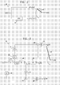
- Fig. 1 is a block diagram that schematically illustrates parts of an ADSL transmitter, in accordance with an embodiment of the present invention.
- polyphase interpolation filters are used for multiplying the sampling rate of a digital Discrete Multi-Tone (DMT) signal that comprises multiple modulated tones, according to the ADSL specification.
- DMT digital Discrete Multi-Tone
- the ADSL transmitter shown in Fig. 1 comprises an analog front-end (AFE) 20 that receives a digital composite DMT signal and converts it to an analog signal suitable for transmission over a telephone line.
- the AFE is typically implemented in a mixed-signal Application-Specific Integrated Circuit (ASIC).
- the AFE comprises a multistage interpolation filter 28 comprising three interpolation filters 30.
- the interpolation filters are implemented using methods described herein. Multistage interpolation filters are further explained in the description of Fig. 7 below. Additionally or alternatively, one or more of filters 30 may have different orders or different transfer functions and thus comprise different coefficients, as will be shown below.
- multistage filter 28 accepts an input sequence of digital samples representing the DMT signal, having an input sampling rate of 4.416 MHz.
- Each interpolation filter 30 performs interpolation by a factor of 2.
- multistage filter 28 performs interpolation by a factor of 8 producing an output sequence having an output sampling rate of 35.328 MHz.
- a Digital-to-Analog (D/A) converter 32 converts the interpolated signal at the output of multistage filter 28 into an analog signal.
- the analog signal is filtered by a Low-Pass Filter (LPF) 34 that suppresses harmonics, image signals and other spurious signals generated by the D/A converter.
- LPF Low-Pass Filter
- the filtered analog signal is fed to a line-driver 36, which performs impedance matching and adjusts the output signal to the appropriate level before transmitting the signal over the telephone line.
- the configuration of multistage filter 28 described above enables efficient VLSI implementation of the ADSL AFE.
- the power consumption of the ASIC is reduced because of the lower sampling rate.
- the ASIC heat dissipation is also improved.
- the lower sampling rate enables the use of low-leakage cells in the ASIC implementation, which provides an additional saving in power consumption.
- Fig. 2 is a block diagram that schematically illustrates a polyphase interpolation filter 49, in accordance with an embodiment of the present invention.
- Filter 49 performs interpolation by a factor of 2, and as such may be used to implement filter 30 of Fig. 1.
- the filter typically has a half-band frequency response, i.e., has low pass-band attenuation (insertion loss) in frequencies lower than half the normalized Nyquist frequency, and high stop-band attenuation (rejection) for frequencies higher than half the normalized Nyquist frequency. (Typical half-band frequency responses are shown in the curves of Fig. 9 below.)
- the filter comprises two parallel branches, or phases.
- the input sequence is first up-sampled. (Typically, a zero sample is inserted between every two original samples. This process is also called "zero stuffing").
- Two parallel transfer functions H 0 (z 2 ) and H 1 (z 2 ) are applied to the up-sampled input sequence, with the phase of H 1 (z 2 ) being delayed by one sample interval compared to the phase of H 0 (z 2 ).
- the input sequence is first filtered in parallel by two transfer functions H 0 (z) and H 1 (z), without up-sampling.
- the two transfer functions are identical to the transfer functions of the original configuration. However, in this case these filters operate at the (lower) input sampling rate, and are thus functions of z and not of z 2 .
- the outputs of the two phases are interleaved (multiplexed) to produce an output sequence having an output sampling rate equal to twice the input sampling rate.
- This implementation has significant practical advantages, enabling the two filters H 0 and H 1 to operate at the lower input sampling rate. Since the input sequence is not up-sampled, H 0 and H 1 process only half of the original number of samples, requiring less memory and computations. Using filters that are functions of z and not of z 2 also effectively reduces the order of these filters, which results in lower memory requirements. When the filters are implemented in an ASIC, the lower memory requirements are translated to reduced power consumption and a smaller die area.
- the use of the Noble identities and the two equivalent filter configurations are described in detail in Section 4.2, pages 118-120, of the book by Vaidyanathan cited above.
- A(z) is a function of z 2 , implying that the filter operates at the (higher) output sampling rate.
- the template filter operates at the (lower) input sampling rate and the summing of the two phases is replaced by interleaving of their outputs.
- an input sequence x(n) is passed simultaneously to two parallel phases, or branches, of filter 49.
- the first phase comprises the input sequence x(n) itself, denoted y 0 .
- the input sequence is filtered by template filter 40, having a transfer function A(z), to produce a sequence denoted y 1 .
- template filter 40 operates at the lower input sampling rate. Therefore, each of the sequences y 0 and y 1 has the same sampling rate as the input sequence x(n).
- a multiplexer 41 operating at twice the input sampling rate, interleaves the two sequences y 0 and y 1 to produce an output sequence denoted y(n) having a sampling rate that is twice the sampling rate of the input sequence x(n).
- the resulting output sequence at the output of multiplexer 41 is thus an interpolation by a factor of two of x(n).
- filter 49 described in Fig. 2 above provides a certain level of stop-band rejection, as dictated by the performance of template filter 40.
- several interpolator stages may be cascaded.
- Cascading N such interpolation stages provides a total transfer function ⁇ H(z) ⁇ N , or explicitly ⁇ 1 ⁇ 2( z -1 +A (z 2 )) ⁇ N .
- the resulting stop-band rejection is N times higher than the rejection of the single-stage filter of Fig. 2.
- the transfer function of this cascade cannot be readily represented as a polyphase structure.
- the following paragraphs describe a method for implementing interpolation filters comprising several cascaded interpolation stages, in a polyphase configuration.
- Filter 50 performs interpolation by 2, and as such may be used to implement filter 30 of Fig. 1.
- the transfer function H(z) is thus expressed as a polyphase - the sum of two phases H 0 (z 2 ) and H 1 (z 2 ), with H 1 (z 2 ) delayed by one sample interval.
- the two phases of filter 50 are expressed in terms of powers of the template filter transfer function A(z), implying a cascade of template filters.
- interpolation filter 50 comprises three template filters 40 connected in cascade.
- the input sequence x(n) and the outputs of the three template filters are processed by ancillary circuitry to produce two polyphase output sequences denoted y 0 (n) and y 1 (n).
- the input sequence and template filter outputs are appropriately delayed using unit delays 42, weighted by a factor of 3 using coefficients 44, combined using summers 46 and multiplied by a gain factor 48.
- the two polyphase output sequences y 0 (n) and y 1 (n) are interleaved by multiplexer 41 to produce the output sequence y(n).
- sequences y 0 (n) and y 1 (n) are interleaved by multiplexer 41 to produce the interpolated output sequence y(n).
- the two phases of interpolation filter 51 can be similarly shown to have a transfer functions equal to H 0 (z) and H 1 (z) above.
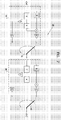
- Figs. 5 and 6 are block diagrams that schematically illustrate generalized configurations of interpolation filters of order N, in accordance with embodiments of the present invention.
- Fig. 5 shows a filter 52, which is the generalized configuration for odd values of N.
- Fig. 6 shows a filter 53, which is the configuration used for even values of N.
- any one of filters 52 and 53 may be used to implement filter 30 of Fig. 1.
- the interpolation filter comprises N template filters 40 connected in cascade.
- the input sequence x(n) and the outputs of the N template filters are delayed using unit delays 42, weighted using N-1 coefficients 44 denoted C 1 ,...,C N-1 , combined using summers 46 and multiplied by gain factor 48, to produce the two polyphase output sequences y 0 (n) and y 1 (n).
- the sequences y 0 (n) and y 1 (n) are interleaved by multiplexer 41 to produce the output sequence y(n).
- the pass-band ripples of these filters accumulate and produce a larger total pass-band ripple. Therefore, in applications that require a flat pass-band, the template filter may have to be specified accordingly.
- Fig. 7 is a block diagram that schematically illustrates multistage interpolation filter 28, in accordance with an embodiment of the present invention.
- the examples shown in Figs. 2-6 above relate to filters used for performing interpolation by a factor of two. In some applications it is desirable to provide interpolation factors higher than two, such as in the ADSL analog front-end example of Fig. 1 above.
- two or more interpolation filters may be connected in series to form a multistage filter. Each filter performs interpolation by two.
- the total interpolation factor of multistage filter 28 is the product of the interpolation factors of the individual stages.
- the sampling rate increases along the series of filters, since the input sampling rate of each filter is equal to the output sampling rate of the preceding filter.
- multistage filter 28 comprises two filters 30 to provide a total interpolation factor of 4.
- multistage filter 28 may comprise any number of interpolation filters.
- filters 30 may comprise filters of any order, such as filters 49-53 described above.
- a series connection of k filters provides a total interpolation factor of 2 k .
- one or more of the filters in multistage filter 28 may have a different template filter transfer function A(z).
- a multistage filter comprising several shorter filter stages is often preferred over the alternative of applying a single, longer filter. Shorter filters typically reduce the overall computational complexity and power consumption of the multistage filter. In addition, each stage is simpler, has more relaxed filtering requirements and can often use simpler coefficient representation.
- the filtering requirements of the first stage are the toughest. These requirements may typically be relaxed when moving forward along the multistage, since the frequencies of image products filtered by each consecutive stage move further apart. This relaxation can be translated to a lower stage filter order, a "softer" transfer function and/or to lower coefficient precision. The relaxed filter requirements typically translates to savings in computational complexity, power consumption and die size.
- an interpolation filter may be transformed into a decimation filter by performing the following transformation steps:
- the polyphase interpolation filter configurations described in Figs 2-6 may be transformed into decimation filters.
- the same benefits provided by the interpolation filter configurations are equally provided by the respective decimation filter configurations.
- the signal flow direction in filter 54 is reversed relative to filter 50 of Fig. 3.
- the input sequence x(n) is separated into even and add input sequences denoted x(2n) and x(2n+1), reversing the operation of multiplexer 41.
- Summers 46 of Fig. 3 have been transformed into branching points, and vice versa.
- the odd and even sequences are appropriately multiplied by coefficients 44, delayed by unit delays 42, and added into the cascade of three template filters 40 using summers 46.
- the output of the cascade is multiplied by gain factor 48 to produce the decimated output sequence y(n).
- the decimated output sequence y(n) operates at the same sampling rate as each of the even and odd sequences x(2n) and x (2n+1) .
- y(n) is a decimation-by-2 of x (n) .
- the value of gain factor 48 in decimation filter 54 is typically half of the corresponding value in interpolation filter 50.
- the reason for choosing this gain value is that for practical input sample sequences, the RMS magnitude of the signal does not change during decimation.
- the interpolation process can be viewed as "zero stuffing" (adding a zero sample between every two input samples) followed by low-pass filtering. This process reduces the average magnitude of the samples by a factor of two, which should be compensated by gain factor 48.
- Fig. 8 shows a decimation filter comprising three template filters.
- the same method may be used to convert a polyphase interpolator filter comprising any number of template filters into a corresponding decimation filter.
- two or more decimation filters 54 may be connected in a multistage connection in order to provide a higher total decimation factor. Any number of decimation filters 54 may be connected in this manner. Connecting k decimation filters in a multistage configuration, each filter decimating by a factor of 2, provides a total decimation factor of 2 k . Additionally or alternatively, one or more of decimation filters 54 in the series may comprise a different template filter 40. Refer also to the description of multistage interpolation filters in Fig. 7 above.
- one of the more computationally-costly tasks is the multiplication of a sample by filter coefficient 44.
- This computational cost may be reduced by replacing "costly" multiplication operations with "low-cost" shift and add operations.
- Multiplying a sample by 2 k is equivalent to shifting the sample, represented as a binary number, k times to the left.
- multiplication may be replaced by summing shifted replicas of the multiplied sample. For example, multiplying a binary sample x by 10 may be implemented by adding a replica of x shifted once (2x) to a replica of x shifted 3 times (8x).
- the following table gives the number of additions required for multiplying coefficients 44 in a single cycle of filter 30, for different values of N: N Additions 2 1 3 4 4 4 5 6
- the total complexity of calculating a single cycle of filter 30 is the number of additions described above, plus N times the complexity of calculating the output of the template filter itself. Therefore, the computational complexity of filtering by template filter 40 has a significant contribution to the overall computational complexity of interpolation filter 30.
- the following table shows the total number of addition operations required to calculate a single cycle of interpolation filter 30 for different values of N.
- the template filter assumed is the third-order half-band filter described above.
- Fig. 9 is a plot that schematically illustrates spectral responses of polyphase interpolation filters 30, in accordance with embodiments of the present invention.
Landscapes
- Physics & Mathematics (AREA)
- Engineering & Computer Science (AREA)
- Computer Hardware Design (AREA)
- Mathematical Physics (AREA)
- Complex Calculations (AREA)
- Analogue/Digital Conversion (AREA)
Applications Claiming Priority (1)
| Application Number | Priority Date | Filing Date | Title |
|---|---|---|---|
| US11/095,244 US7680869B2 (en) | 2005-03-30 | 2005-03-30 | Interpolation and decimation using newton polyphase filters |
Publications (1)
| Publication Number | Publication Date |
|---|---|
| EP1708363A2 true EP1708363A2 (fr) | 2006-10-04 |
Family
ID=36603713
Family Applications (1)
| Application Number | Title | Priority Date | Filing Date |
|---|---|---|---|
| EP06111953A Withdrawn EP1708363A2 (fr) | 2005-03-30 | 2006-03-29 | Filtres interpolateurs et décimateurs ayant des configurations polyphase |
Country Status (2)
| Country | Link |
|---|---|
| US (1) | US7680869B2 (fr) |
| EP (1) | EP1708363A2 (fr) |
Families Citing this family (6)
| Publication number | Priority date | Publication date | Assignee | Title |
|---|---|---|---|---|
| US7720304B2 (en) * | 2005-05-31 | 2010-05-18 | Broadcom Corporation | System and method for implementing graphics and video scaling algorithm using interpolation based on symmetrical polyphase filtering |
| JP2008167056A (ja) * | 2006-12-27 | 2008-07-17 | Rohm Co Ltd | デジタル信号処理回路およびδς変調器ならびにこれらを利用した電子機器 |
| KR20100042817A (ko) * | 2008-10-17 | 2010-04-27 | 삼성전자주식회사 | 다단계 채널 필터를 가지는 무선 통신 시스템의 송수신 장치 |
| EP2278714B1 (fr) * | 2009-07-02 | 2015-09-16 | Nxp B.V. | Étage de puissance |
| US8867592B2 (en) | 2012-05-09 | 2014-10-21 | Nxp B.V. | Capacitive isolated voltage domains |
| CN113985340B (zh) * | 2021-10-11 | 2024-07-30 | 北京智芯微电子科技有限公司 | 电能计量芯片及其相位补偿方法和相位补偿装置 |
Family Cites Families (14)
| Publication number | Priority date | Publication date | Assignee | Title |
|---|---|---|---|---|
| IT1119567B (it) * | 1979-11-08 | 1986-03-10 | Cselt Centro Studi Lab Telecom | Equalizzatore numerico adattativo per ricevitori di segnali dati utilizzanti una modulazione differenziale di fase |
| US4835723A (en) * | 1987-04-03 | 1989-05-30 | Tektronix, Inc. | Phase coordinated multistage digital filter |
| US5621675A (en) * | 1994-11-02 | 1997-04-15 | Advanced Micro Devices, Inc. | Digital decimation and compensation filter system |
| US5978823A (en) * | 1997-01-27 | 1999-11-02 | Hitachi America, Ltd. | Methods and apparatus for implementing and controlling a digital modulator |
| US6668029B1 (en) * | 1998-12-11 | 2003-12-23 | Hitachi America, Ltd. | Methods and apparatus for implementing digital resampling circuits |
| US6625628B1 (en) * | 1999-03-30 | 2003-09-23 | Nec Corporation | Method and apparatus for digital filter |
| US6600495B1 (en) * | 2000-01-10 | 2003-07-29 | Koninklijke Philips Electronics N.V. | Image interpolation and decimation using a continuously variable delay filter and combined with a polyphase filter |
| DE10029424C2 (de) * | 2000-06-15 | 2002-04-18 | Infineon Technologies Ag | Digitales Interpolationsfilter |
| US6590510B2 (en) * | 2000-06-16 | 2003-07-08 | Lionel Jacques Woog | Sample rate converter |
| US7047264B2 (en) * | 2001-03-02 | 2006-05-16 | Samsung Electronics Co., Ltd. | Frequency converter |
| US7010557B2 (en) * | 2002-03-27 | 2006-03-07 | Broadcom Corporation | Low power decimation system and method of deriving same |
| US6993464B2 (en) * | 2002-12-03 | 2006-01-31 | Chunghwa Telecom Co., Ltd. | Optimized filter parameters design for digital IF programmable downconverter |
| US7747666B2 (en) * | 2004-08-09 | 2010-06-29 | L-3 Communications Corporation | Parallel filter realization for wideband programmable digital radios |
| US7480689B2 (en) * | 2004-11-19 | 2009-01-20 | Massachusetts Institute Of Technology | Systolic de-multiplexed finite impulse response filter array architecture for linear and non-linear implementations |
-
2005
- 2005-03-30 US US11/095,244 patent/US7680869B2/en active Active
-
2006
- 2006-03-29 EP EP06111953A patent/EP1708363A2/fr not_active Withdrawn
Also Published As
| Publication number | Publication date |
|---|---|
| US20060224649A1 (en) | 2006-10-05 |
| US7680869B2 (en) | 2010-03-16 |
Similar Documents
| Publication | Publication Date | Title |
|---|---|---|
| Kwentus et al. | Application of filter sharpening to cascaded integrator-comb decimation filters | |
| KR100799406B1 (ko) | 대역 내 신호의 감쇠를 보상하기 위한 디지털 샘플링레이트 변환기 | |
| US20030172098A1 (en) | Multi-rate digital filter for audio sample-rate conversion | |
| US5831879A (en) | Digital transmit filter | |
| US7047264B2 (en) | Frequency converter | |
| US5717617A (en) | Rate change filter and method | |
| Jiang et al. | Efficient digital filtering architectures using pipelining/interleaving | |
| US7248189B2 (en) | Programmable sample rate conversion engine for wideband systems | |
| JP2003526243A (ja) | 入力信号の周波数バンドを分割するための装置 | |
| KR20040058297A (ko) | 이산 시간 필터와 이를 포함하는 통신 디바이스 및 방법 | |
| Kumar et al. | Exploiting coefficient symmetry in conventional polyphase FIR filters | |
| CN114024553B (zh) | 多通道基带至射频的上变频方法、系统及电子设备 | |
| US4953118A (en) | Nonrecursive half-band filter | |
| US6000834A (en) | Audio sampling rate conversion filter | |
| US7680869B2 (en) | Interpolation and decimation using newton polyphase filters | |
| WO2002086755A1 (fr) | Procede et dispositif de traitement parallele des signaux | |
| CN101394161A (zh) | 采样率转换器 | |
| Chan et al. | Design and complexity optimization of a new digital IF for software radio receivers with prescribed output accuracy | |
| CN1195352C (zh) | 抽样数据数字滤波系统和对抽样数据滤波的方法 | |
| George et al. | Continuously variable bandwidth sharp FIR filters with low complexity | |
| Sheikh et al. | Efficient sample rate conversion for multi-standard software defined radios | |
| Johansson et al. | Adjustable fractional-delay FIR filters using the Farrow structure and multirate techniques | |
| US7724162B2 (en) | Circuit for sample rate conversion | |
| EP1134892A1 (fr) | Structure de filtre numérique | |
| Zhu et al. | ASIC implementation architecture for pulse shaping FIR filters in 3G mobile communications |
Legal Events
| Date | Code | Title | Description |
|---|---|---|---|
| PUAI | Public reference made under article 153(3) epc to a published international application that has entered the european phase |
Free format text: ORIGINAL CODE: 0009012 |
|
| AK | Designated contracting states |
Kind code of ref document: A2 Designated state(s): AT BE BG CH CY CZ DE DK EE ES FI FR GB GR HU IE IS IT LI LT LU LV MC NL PL PT RO SE SI SK TR |
|
| AX | Request for extension of the european patent |
Extension state: AL BA HR MK YU |
|
| STAA | Information on the status of an ep patent application or granted ep patent |
Free format text: STATUS: THE APPLICATION IS DEEMED TO BE WITHDRAWN |
|
| 18D | Application deemed to be withdrawn |
Effective date: 20121002 |