EP1708801B1 - Vorrichtung und verfahren zum belüften/mischen von wasser - Google Patents
Vorrichtung und verfahren zum belüften/mischen von wasser Download PDFInfo
- Publication number
- EP1708801B1 EP1708801B1 EP05708133A EP05708133A EP1708801B1 EP 1708801 B1 EP1708801 B1 EP 1708801B1 EP 05708133 A EP05708133 A EP 05708133A EP 05708133 A EP05708133 A EP 05708133A EP 1708801 B1 EP1708801 B1 EP 1708801B1
- Authority
- EP
- European Patent Office
- Prior art keywords
- water
- aeration
- propeller
- feed pipe
- aeration unit
- Prior art date
- Legal status (The legal status is an assumption and is not a legal conclusion. Google has not performed a legal analysis and makes no representation as to the accuracy of the status listed.)
- Expired - Lifetime
Links
Images


Classifications
-
- B—PERFORMING OPERATIONS; TRANSPORTING
- B01—PHYSICAL OR CHEMICAL PROCESSES OR APPARATUS IN GENERAL
- B01F—MIXING, e.g. DISSOLVING, EMULSIFYING OR DISPERSING
- B01F25/00—Flow mixers; Mixers for falling materials, e.g. solid particles
- B01F25/20—Jet mixers, i.e. mixers using high-speed fluid streams
- B01F25/25—Mixing by jets impinging against collision plates
-
- B—PERFORMING OPERATIONS; TRANSPORTING
- B01—PHYSICAL OR CHEMICAL PROCESSES OR APPARATUS IN GENERAL
- B01F—MIXING, e.g. DISSOLVING, EMULSIFYING OR DISPERSING
- B01F23/00—Mixing according to the phases to be mixed, e.g. dispersing or emulsifying
- B01F23/20—Mixing gases with liquids
- B01F23/23—Mixing gases with liquids by introducing gases into liquid media, e.g. for producing aerated liquids
- B01F23/234—Surface aerating
- B01F23/2341—Surface aerating by cascading, spraying or projecting a liquid into a gaseous atmosphere
- B01F23/23413—Surface aerating by cascading, spraying or projecting a liquid into a gaseous atmosphere using nozzles for projecting the liquid into the gas atmosphere
-
- B—PERFORMING OPERATIONS; TRANSPORTING
- B01—PHYSICAL OR CHEMICAL PROCESSES OR APPARATUS IN GENERAL
- B01F—MIXING, e.g. DISSOLVING, EMULSIFYING OR DISPERSING
- B01F23/00—Mixing according to the phases to be mixed, e.g. dispersing or emulsifying
- B01F23/20—Mixing gases with liquids
- B01F23/23—Mixing gases with liquids by introducing gases into liquid media, e.g. for producing aerated liquids
- B01F23/234—Surface aerating
- B01F23/2342—Surface aerating with stirrers near to the liquid surface, e.g. partially immersed, for spraying the liquid in the gas or for sucking gas into the liquid, e.g. using stirrers rotating around a horizontal axis or using centrifugal force
- B01F23/23421—Surface aerating with stirrers near to the liquid surface, e.g. partially immersed, for spraying the liquid in the gas or for sucking gas into the liquid, e.g. using stirrers rotating around a horizontal axis or using centrifugal force the stirrers rotating about a vertical axis
-
- B—PERFORMING OPERATIONS; TRANSPORTING
- B01—PHYSICAL OR CHEMICAL PROCESSES OR APPARATUS IN GENERAL
- B01F—MIXING, e.g. DISSOLVING, EMULSIFYING OR DISPERSING
- B01F35/00—Accessories for mixers; Auxiliary operations or auxiliary devices; Parts or details of general application
- B01F35/10—Maintenance of mixers
- B01F35/145—Washing or cleaning mixers not provided for in other groups in this subclass; Inhibiting build-up of material on machine parts using other means
- B01F35/1452—Washing or cleaning mixers not provided for in other groups in this subclass; Inhibiting build-up of material on machine parts using other means using fluids
-
- B—PERFORMING OPERATIONS; TRANSPORTING
- B01—PHYSICAL OR CHEMICAL PROCESSES OR APPARATUS IN GENERAL
- B01F—MIXING, e.g. DISSOLVING, EMULSIFYING OR DISPERSING
- B01F2101/00—Mixing characterised by the nature of the mixed materials or by the application field
- B01F2101/305—Treatment of water, waste water or sewage
-
- B—PERFORMING OPERATIONS; TRANSPORTING
- B01—PHYSICAL OR CHEMICAL PROCESSES OR APPARATUS IN GENERAL
- B01F—MIXING, e.g. DISSOLVING, EMULSIFYING OR DISPERSING
- B01F2215/00—Auxiliary or complementary information in relation with mixing
- B01F2215/04—Technical information in relation with mixing
- B01F2215/0413—Numerical information
- B01F2215/0436—Operational information
- B01F2215/045—Numerical flow-rate values
-
- B—PERFORMING OPERATIONS; TRANSPORTING
- B01—PHYSICAL OR CHEMICAL PROCESSES OR APPARATUS IN GENERAL
- B01F—MIXING, e.g. DISSOLVING, EMULSIFYING OR DISPERSING
- B01F2215/00—Auxiliary or complementary information in relation with mixing
- B01F2215/04—Technical information in relation with mixing
- B01F2215/0413—Numerical information
- B01F2215/0436—Operational information
- B01F2215/0463—Numerical power values
Definitions
- the invention is concerned with an aeration system in accordance with claim 1 and method in accordance with claim 5 for mixing and/or aeration of water.
- Biological treatment is an Important phase in the treatment of wastewaters and it is also the phase consuming most energy.
- biological treatment carried out by means of aeration it is necessary to continuously feed oxygen into the water in order to enable bacterial activity in the process.
- the oxygen concentration decreases also in natural waters during the long winter season, when the ice covering prevents a natural oxidation through the air. This phenomenon might lead to oxygen depletion, death of fish and a final pollution of the lake.
- Biological treatment is also used for e.g. removal of gases, such as radon, from the water by aeration.
- Bottom aeration is the most common way for aeration of waters.
- air is pumped into the water through a membrane with holes on the bottom of the basin.
- Attempts have been made to start using surface aeration instead of bottom aeration, primarily of maintenance reasons.
- air has been fed to rotating propellers on or near the surface of the water, which propellers have mixed air with streaming water.
- propellers have mixed air with streaming water.
- Such devices are known, in which different flow pieces have been placed in the streams created by the propellers in order to improve the transfer of the air into the water and the mixing of the air with the water.
- the main drawback with these devices is their contamination and clogging in use.
- they have often required separate water mixers to keep the whole water content in the basin in a sufficient movement, whereby the waste water sludge can be prevented from falling down to the bottom of the basin.
- ejectors have been used for aeration, in which a water jet has sucked air In itself and this jet has then been lead to the bottom of the basin, whereby circulation has been achieved in the basin at the same time.
- Characteristic for all surface aeration devices have been their efficiency, in other words, the amount of dissolved oxygen in each energy unit has been low.
- the aeration causes ca 80% of the energy costs of a waste water treatment plant (i.e. an activated sludge plant, i.e. a plant using biological treatment) and this electricity consumption corresponds to ca 30% of the operational costs of the waste water treatment plant
- the energy consumption is therefore of essential importance in aeration.
- Typical oxidation effects in practice are, when it is question about a fine bubble aeration unit, which works as a bottom aerator 1,7-3,0 kgO2/kWh, a coarse bubble aerator which works as a bottom aerator: 1,7-2,3kgO2/kWh, a surface aeration 1,3-2.2kgO2/kWh or a combination aerator (OKI): 1,5-3,2kgO2/kWh.
- the maintenance of a bottom aerator is difficult.
- the basin has to be emptied for the service (a part of them having separate bottom floats, which can be lifted one by one).
- the service is expensive and takes several weeks.
- the aeration system (including aeration plates, pipes, the installation, a compressor hall and the compressors) has cost 300.000 EUR.
- the service which has to be performed with intervals of 4-6 years, costs 40-50.000 EUR.
- Publication US 3.998.389 disclose an aeration system in accordance with the preamble of claim 1.
- the water stream achieved with a propeller pump is lead to one or more annular nozzles on the surface of the water, in which units the water stream sucks air into it, which is efficiently mixed with the water thereby aerating it
- the height of the nozzle opening should be restricted as well. Then the size of the bubbles that will be formed in the water remains small and are evenly distributed thereby enabling a high solution rate. This fact results in relatively small aeration units and most usually, the unit contains numerous aeration units. Only in the very smallest apparatuses it is possible to manage with only one aeration unit or nozzle opening.
- This invention is concerned with a surface aeration apparatus/mixer.
- a feed pipe foreseen with a propeller pump belongs to the apparatus, with which pipe ground water poor of oxygen is sucked to the aerator. Near the surface, the feed pipe is branched into transversal feed pipes parallel with the surface.
- the water is lead to a circular nozzle opening. In the nozzle opening, the pressure energy is converted to kinetic energy.
- the water jet streaming from the nozzle opening sucks surrounding air to itself both beneath and above the jet, which is mixed with the water jet in the form of small bubbles.
- the jet maintains a big part of its kinetic en ergy until it meets the cylindrical covering or the surrounding water.
- the nozzle opening is vertical in order to lead the water jet out horizontally from the feed pipe
- the water of the basin When the water is taken into the apparatus from the bottom of the basin and returned back to the surface of the basin, the water of the basin will be efficiently circulated and the incoming water is as oxygen-poor as possible. This fact essentially increases the performance of the apparatus, In other aeration apparatuses, the oxygen content of the water coming to the aeration apparatus is of average level or the apparatus circulates the same relatively oxidized water. At the same time as the apparatus oxidizes efficiently, It circulates the water of the basin thereby preventing the falling of the sludge to the bottom. Thereby, there is no need for separate mixers.
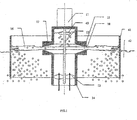
- FIG. 1 presents a cross-sectional view of the apparatus of the invention, in which water is aerated in a basin.
- the feed pipe therein has been marked with reference number 14.
- the propeller pump consists of the motor 11, an axle 12 between the propeller and the motor and of a propeller 13.
- the water is branched into horizontal nozzle rings 15, the construction of which is such that the inlet consists of conical nozzles 17, which end up to an annular nozzle opening 18.
- the conical nozzle ends up to a nozzle opening and is abruptly expanding thereafter.
- An ejector is hereby achieved.
- the construction between the nozzle rings 15 works as an ejector and causes a water jet 16, which sucks air in itself above and beneath the jet The water is aerated, the air is efficiently mixed with the water jet and is returned back to the basin.
- a propeller 40 for the pre-aeration which is opposite-handed to the propeller 13 of the propeller pump so that it strives to push the water down.
- the propeller 40 which is in the upper end of the axle 12 between the motor and the propeller, mixes air in the turbulent water, which is efficiently mixed with the water and is removed from the aerator through the nozzle 17 in the form of a water jet,
- the bubbles are in strong movement, or turbulence, during the whole process.
- the size of the propeller 40 is smaller than the propeller 14 of the propeller pump as the amount of air needed is small and, in addition, a big amount of water could cause a gravitation of the propeller of the propeller pump, which essentially would weaken the function of the pump.
- the pressure of the water raised by the propeller pump is converted to kinetic energy.
- Water is sucked from the bottom of the basin by means of the propeller pump 13 through the pipe 14.
- the propeller pump 13 sucks water and lifts it up to the aeration unit
- the water arrives to the aeration unit from the feed pipe 14.
- the conical surface of the nozzle 17 of the aeration unit decreases the flow resistance of the water.
- the pressure energy is completely converted to kinetic energy.
- the water jet 16 outwards from the nozzle 17 causes an under pressure, which sucks air to the water jet 16.
- the water becomes turbulent in the jet and as the under pressure draws air to it, this air is now efficiently mixed with the water and a big part of this oxygen is dissolved in the water, whereby aeration takes place.
- the jet After the nozzle opening, the jet is quickly expanded in the horizontal plane and simultaneously, the thickness of the jet is decreased in the vertical direction in the same proportion by further increasing the aeration and turbulence. Finally, the water jet meets the outside water, which increases the effect of the mixing and aeration even more or it meets the cylindrical covering 41.
- the third step of the aeration - the water jet meets the wall
- the water jet 16 from the nozzle which water jet consists of water and air, meets the wall that is relatively nearby, in other words the cylindrical covering 41, thereby causing a strong impact, which splits the water jet into small water droplets and air bubbles.
- this wall has been 20- 50 cm from the outer edge of the aeration unit
- the apparatus has to be so high above the water that the jet is not damped (drowned) in the surrounding water, i.e. the aeration unit does not work if it is immersed. In that case any water jet would not be formed, the aeration unit would not be able to suck any air into a water jet and any radical collision with an outer wall, or with the cylindrical covering 41, would not take place.
- a cylindrical covering 41 has been built around the aeration unit.
- the mixture of water and air is mixed and thereby causes aeration.
- more air from the surrounding atmosphere is mixed therein at the collision point, which fact increases the efficiency of the aeration.
- the forth step of the aeration-the mixture of water and air ends up to the water below the cylindrical covering
- the apparatus can also be used without any cylindrical covering 41. If the edges of the aeration basin are close to the outer edge of the aeration unit a corresponding phenomenon is achieved by making use of the form of the basin and the above-mentioned method/apparatus.
- the form of the apparatus can also be something else than a body of revolution.
- the advantage of using a body of revolution is, however, the big length 18 of the nozzle opening.
- the gain of the aeration is in proportion to the length of the nozzle opening 18 (e.g. when the diameter is 30 cm at the nozzle opening, the length of the nozzle opening is ⁇ x 30 cm, or ca 94 cm).
- the jet is formed in the annular opening, whereby the jet is reduced when the radius increases. Good results were achieved in tests when the diameter of the nozzle opening was 75mm and 290 mm. In the contrary, when the diameter of the nozzle opening was 750 mm, the result was bad. This is a consequence of the fact that the water jet did not expand so fast anymore in the horizontal plane and thus it did not become thinner in the vertical direction, which is a condition for an efficient aeration in this method.
- the radius of the nozzle opening is 40 mm and the water jet outwards from the nozzle opening has the length of 360 mm. Then the water jet having a thickness of 20 mm has become thinner in the end of the water jet having a thickness of only 2 mm. If the radius of the nozzle opening would have been 720 mm and the length of the jet 360 mm, the jet would only have reduced to a thickness of 14 mm.
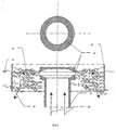
- FIG. 2 and 3 present the aeration unit more in detail.
- Figure 3 is a detailed picture of the aeration unit, wherein the things explained in connection with figure 2 are clearer.
- the water comes between the nozzle rings 15 after the feed pipe 14.
- the upper and lower nozzle rings form an ejector (the upper nozzle ring continues and forms here also a cover).
- the conical nozzle rings 15 form a nozzle 17, that ends up to an annular nozzle opening 18.
- the speed of the water increases in the nozzle 17 and the pressure energy is converted to kinetic energy.
- the nozzle opening expands abruptly when the nozzle rings end.
- the water jet 16 streaming out from the opening forms an under pressure.
- the air above the Jet 16 is sucked into the jet 16.
- the under pressure formed beneath the jet 16 sucks air to the jet as well. Air is also absorbed through the jet from above. The absorbed air is mixed with the water and moves along with the water. In this opening the water jet takes a part of the air with itself. In this way, such conditions, that are as advantageous as possible, have been created for the mixing of the water and the air. As only a little oxygen is dissolved into the water, the amount of air fed shall be relatively small: This is achieved with right dimensions for the nozzle. So that the air bubbles coming further to the water jet would be as evenly distributed as possible, the height of the nozzle opening 18 shall be relatively small. The best results have been achieved when the height of the nozzle opening has been 10-45 mm.
- the water comes along the feed pipe in the direction of the arrows 36 to the aeration unit.
- the water 16 is removed between the nozzle rings 15 according to arrow 37 to the surrounding water In the form of a jet.
- the water achieves its highest speed in the narrowest point, i.e. in the nozzle opening 18, from which it is ejected outwards in the direction of the surface of the surrounding water.
- the nozzle 17 works as an ejector by absorbing air to the water jet from outside.
- the water that is ejected outwards absorbs air and mixes it efficiently with the water by causing aeration of the water, i.e. dissolving of oxygen in the water.
- the water jet is thin enough water is absorbed from both sides of the water jet, above and beneath.
- the bubbles are very small and In this way there is formed a contact surface as big as possible between the air and the water thereby causing an efficient dissolving of oxygen into the water.
- the efficiency of the mixing is increased by a step, in which the mixture of water and air collides with the outside water mass or the cylindrical covering 41.
- the apparatus was also tested so that additional holes led to the nuzzle opening, through which holes more air was received in them.
- the dissolving of oxygen was decreased as the size of the bubbles increased and there was relatively seen unnecessary much air in the water.
- the surfaces are treated to be conical in order to make the energy consumption as low as possible.
- the construction of the upper part of the aeration unit appears from the figure.
- the lower part is otherwise identical except for the feed pipe connected thereto.
- Figure 4 presents an aeration unit placed in water. It is important that the aeration unit 20/nozzle opening 18 is placed into the right depth 22 (a depth in which the water jet has not jet been essentially damped), 23 (the nozzle opening 18 is completely above, the water surface but near the water surface) of the water. If the apparatus is too deep, in the water 21, no water jet is formed and the aeration unit can not absorb any air at all through the water. Then the apparatus does not aerate at all, the water only flows through it thereby causing mixing without aeration. If the apparatus is too high in relation to the water surface 24, the energy consumption at the pumping of the water increases, but the result does not improve.
- a water column of 20 cm is used in order to achieve the movement and aeration of the water
- the aeration unit is placed in accordance with figure 4 , whereby the apparatus works as it should and the energy consumption is minimized.
- the apparatus is placed in water so that the water jet is clearly distinguished and the aeration unit absorbs air also from or to below the jet 16 but still as down as possible so that any unnecessary pumping of the above kind would not be needed.
- the nozzle opening 18 is partly or completely under the water surface but not deeper than that, a high efficiency is achieved.
- the apparatus of the invention can be used also for oxidizing natural waters.
- the apparatus sucks oxygen-poor ground water to the apparatus, wherein thy water is oxidized and it returns to the surface of the lake.
- the warmer ground water maintains an open hole in the ice. If the temperature graduation of the lake is wished to be maintained, the oxidized water can be lead deeper with a return pipe.
- saturated gases in the water are released in connection with the aeration, such as nitrogen, carbon dioxide, ammonia and radon.
- the different steps in the water purification takes place successively in the same space.
- the apparatus can be used after aeration for example for removal of nitrogen by stopping the oxidation but by continuing the mixing. In this way, the aerobic and the anaerobic steps of the process can be repeated alternately in the same basin.
Landscapes
- Chemical & Material Sciences (AREA)
- Chemical Kinetics & Catalysis (AREA)
- Aeration Devices For Treatment Of Activated Polluted Sludge (AREA)
Claims (5)
- Belüftungssystem zum Belüften und/oder Mischen von Wasser, aufweisend mindestens eine Belüftungseinheit (20) mit
einer im Innern eines Speiserohrs (14) angeordneten Schraubenpumpe (13), mit welcher das zu belüftende Wasser aus der Tiefe in das Speiserohr (14) gesaugt wird, und
einem Düsenring (15,38) in der Belüftungseinheit (20), wobei sich das Speiserohr (14) in dem oberen Teil der Belüftungseinheit (20) erweitert und dabei einen konischen Raum bildet, der als eine Düse (17) wirkt, die in einer ringförmigen Düsenöffnung (18) endet,
dadurch gekennzeichnet,
daß die Belüftungseinheit (20) in dem Wasser in die richtige Tiefe (22,23) positionierbar ist, derart, daß die ringförmige Düsenöffnung (18) an oder nahe an der Oberfläche des Wassers angeordnet ist und daß der von der Pumpe/Schraube (13) hervorgerufene Wasserstrom so gestaltet ist, daß er sich zu der ringförmigen Düsenöffnung (18), die an oder nahe an der Wasseroberfläche angeordnet ist, bewegt,
daß um die Belüftungseinheit (20) herum eine zylindrische Abdeckung (41) vorhanden ist, wobei die zylindrische Abdeckung (41) so gestaltet ist, daß aus der ringförmigen Düsenöffnung (18) austretende Wasserstrahlen (16) auf sie aufprallen,
daß in dem oberen Teil des Systems eine zusätzliche kleinere Schraube (40) vorhanden ist, deren Drehrichtung sich von der Drehrichtung der Schraube der Schraubenpumpe (13) unterscheidet, und
daß die ringförmige Düsenöffnung (18) vertikal ist, um den Wasserstrahl horizontal aus dem Speiserohr (14) austreten zu lassen. - Belüftungssystem nach Anspruch 1, dadurch gekennzeichnet, daß der konische Raum in dem oberen Teil der Belüftungseinheit (20) durch peripheres Zuschneiden des Speiserohrs erzielt worden ist, wodurch sich eine Düse (17) und eine Düsenöffnung (18) ergibt.
- Belüftungseinheit nach Anspruch 2, dadurch gekennzeichnet, daß der obere Teil und der untere Teil des Zuschnitts des Speiserohrs aus einem Stück sind und durch in dem Rohr belassene Befestigungen aneinander befestigt sind.
- Belüftungssystem nach Anspruch 1 und 3, dadurch gekennzeichnet, daß durch Ändern der Drehrichtung der Schraubenpumpe (13) und durch Halten der Belüftungseinheit (20) unter Wasser die Zirkulation und das Mischen des Wassers verstärkt werden können und die Vorrichtung gereinigt werden kann.
- Verfahren zum Belüften/Mischen von Wasser in einer Belüftungseinheit (20), die eine im Innern eines Speiserohrs angeordnete Schraubenpumpe (13), mit Hilfe derer das Wasser in das Speiserohr (14) gesaugt wird, ein Speiserohr (14), in welches das Wasser aus der Tiefe gesaugt wird, und einen Düsenring (15,38) der Belüftungseinheit aufweist, in welchem Verfahrena) dem Speiserohr (14) der Belüftungseinheit (20), die in dem Wasser ist, ein mit der Schraubenpumpe (13) erzeugter Wasserstrom zugeleitet wird,b) das Wasser von dem Speiserohr aus über einen als eine Düse (17) wirkenden und sich als ein konischer Raum erstreckenden Teil in dem oberen Teil des Speiserohrs geleitet wird und weiter zu einer ringförmigen Düsenöffnung (18), in der die Düse (17) endet und die an oder nahe an der Wasseroberfläche angeordnet ist, geleitet wird, undc) das Wasser (16) über die ringförmige Düsenöffnung (18) in Form eines Wasserstrahls weggeleitet wird,
gekennzeichnet
durch Verwendung einer Belüftungseinheit (20), die mit einer zylindrischen Abdeckung (41) umgeben ist und die in ihrem oberen Ende eine zusätzliche kleinere Schraube aufweist, deren Drehrichtung sich von der Drehrichtung der Schraube der Schraubenpumpe (13) unterscheidet,
und durch Verwendung einer ringförmigen Düsenöffnung (18), die vertikal ist, um den Wasserstrahl horizontal aus dem Speiserohr (14) austreten zu lassen,
und durch Ermöglichung eines Aufprallens des aus der ringförmigen Düsenöffnung (18) austretenden Wasserstrahls auf die als eine Wand wirkende zylindrische Abdeckung (41), um den Wasserstrahl in kleine Wassertröpfchen und Luftblasen zu teilen,
und durch Durchführen eines Vorbelüftungsschritts, in welchem Wasser mit Hilfe der kleineren Schraube (40) nach unten gedrückt wird und mit Luft vermischt wird und das Wasser über die Düse (17) in Form eines Wasserstrahls aus der Belüftungseinheit (20) weggeführt wird.
Applications Claiming Priority (2)
| Application Number | Priority Date | Filing Date | Title |
|---|---|---|---|
| FI20040113A FI120234B (fi) | 2004-01-27 | 2004-01-27 | Laite ja menetelmä veden ilmastamiseksi/sekoittamiseksi |
| PCT/FI2005/000051 WO2005070526A1 (en) | 2004-01-27 | 2005-01-26 | Apparatus and method for aeration/mixing of water |
Publications (2)
| Publication Number | Publication Date |
|---|---|
| EP1708801A1 EP1708801A1 (de) | 2006-10-11 |
| EP1708801B1 true EP1708801B1 (de) | 2009-08-05 |
Family
ID=30129443
Family Applications (1)
| Application Number | Title | Priority Date | Filing Date |
|---|---|---|---|
| EP05708133A Expired - Lifetime EP1708801B1 (de) | 2004-01-27 | 2005-01-26 | Vorrichtung und verfahren zum belüften/mischen von wasser |
Country Status (6)
| Country | Link |
|---|---|
| US (1) | US7644909B2 (de) |
| EP (1) | EP1708801B1 (de) |
| AT (1) | ATE438458T1 (de) |
| DE (1) | DE602005015822D1 (de) |
| FI (1) | FI120234B (de) |
| WO (1) | WO2005070526A1 (de) |
Families Citing this family (17)
| Publication number | Priority date | Publication date | Assignee | Title |
|---|---|---|---|---|
| US8146894B2 (en) * | 2004-06-21 | 2012-04-03 | Hills Blair H | Apparatus for mixing gasses and liquids |
| CN100337943C (zh) * | 2005-09-02 | 2007-09-19 | 田伯海 | 旋混曝气装置 |
| FI20051053A7 (fi) * | 2005-10-19 | 2007-04-20 | Waterix Oy | Jäähdytin |
| DE102006052922B4 (de) * | 2006-11-08 | 2012-02-23 | Itt Manufacturing Enterprises, Inc. | Vorrichtung und Verfahren zur Verbesserung der Durchmischung bei der UV-Desinfektion von Flüssigkeiten |
| CN101725490A (zh) * | 2008-10-28 | 2010-06-09 | 翟爱民 | 能量收集转换 |
| US8523984B2 (en) * | 2010-09-19 | 2013-09-03 | Medora Environmental, Inc. | Water circulation systems with air stripping arrangements for municipal water tanks, ponds, and other potable bodies of water |
| CN103007870B (zh) * | 2011-09-20 | 2014-12-17 | 中国石油化工股份有限公司 | 一种喷嘴撞击流重排反应器 |
| CA2926209A1 (en) | 2013-10-22 | 2015-04-30 | Medora Environmental, Inc. | Air-powered water circulation systems for ponds, lakes, municipal water tanks, and other bodies of water |
| EP3047898B1 (de) * | 2015-01-20 | 2017-09-06 | General Electric Technology GmbH | Anordnung eines Brenners und einer Vorrichtung für eine selektive nicht-katalytische Reduktion und Düse zur Einspritzung |
| US10589237B2 (en) * | 2015-09-28 | 2020-03-17 | Hamilton Sundstrand Corporation | Systems and methods for gas disposal |
| CN105366825B (zh) * | 2015-11-18 | 2018-05-04 | 亚太水处理(天长)有限公司 | 一种抽吸式倒伞型表面曝气机 |
| CN105715458A (zh) * | 2016-03-24 | 2016-06-29 | 湖南工业大学 | 一种带漏斗式液气混合器和复合爆气池的爆气发电装置 |
| CN105673342A (zh) * | 2016-03-24 | 2016-06-15 | 湖南工业大学 | 带漏斗式液气混合器和复合爆气池的爆气发电装置 |
| CN105673344A (zh) * | 2016-04-05 | 2016-06-15 | 湖南工业大学 | 带漏斗式液气混合器的爆气发电装置 |
| CN105804946A (zh) * | 2016-04-05 | 2016-07-27 | 湖南工业大学 | 一种带漏斗式液气混合器的爆气发电装置 |
| CN108609723A (zh) * | 2018-06-15 | 2018-10-02 | 河南泽衡环保科技股份有限公司 | 新型旋流式曝气器 |
| CN113754087B (zh) * | 2021-09-07 | 2022-04-01 | 江苏开放大学(江苏城市职业学院) | 一种曝气装置 |
Family Cites Families (25)
| Publication number | Priority date | Publication date | Assignee | Title |
|---|---|---|---|---|
| US780780A (en) * | 1904-04-29 | 1905-01-24 | Carl R Culley | Nozzle. |
| US1867824A (en) * | 1930-08-18 | 1932-07-19 | Georgia A Hammerly | Apparatus for mixing fluids |
| US1992762A (en) * | 1931-04-02 | 1935-02-26 | Pease Anthony Equipment Co | Method of washing gases |
| FR788343A (fr) * | 1935-04-05 | 1935-10-08 | Dispositif de traitement des eaux usées | |
| US2165889A (en) * | 1936-07-17 | 1939-07-11 | Dorr Co Inc | Aeration of liquids |
| US2186371A (en) * | 1937-08-12 | 1940-01-09 | Jr Augustus C Durdin | Apparatus for and method of removing supernatant matter from sewage and other liquids |
| US3416729A (en) * | 1966-08-12 | 1968-12-17 | Richards Of Rockford Inc | Liquid aerator |
| FR2076672A5 (en) * | 1970-01-23 | 1971-10-15 | Sogreah | Mixing unit - esp for aeration of waste water |
| US3735926A (en) * | 1971-05-27 | 1973-05-29 | Richards Of Rockford Inc | Liquid spray device with fixed and rotatable diffusers |
| US3871581A (en) * | 1971-09-13 | 1975-03-18 | Environmental Products Inc | Aerating apparatus having ballast means therefor |
| US3737105A (en) * | 1971-09-13 | 1973-06-05 | Peabody Engineering Corp | Double spray nozzle |
| US3797809A (en) * | 1972-04-20 | 1974-03-19 | Sydnor Hydrodynamics Inc | Aerator apparatus |
| US3771724A (en) * | 1972-07-19 | 1973-11-13 | Richards Of Rockford Inc | Apparatus and process for spraying liquids |
| US3998389A (en) * | 1972-07-19 | 1976-12-21 | Richards Of Rockford | Apparatus for gas treatment of liquids |
| US3911065A (en) * | 1973-04-17 | 1975-10-07 | Ernest J Martin | Liquid aerator or the like |
| US4089620A (en) * | 1976-10-26 | 1978-05-16 | Riga, Inc. | Floating pumping device |
| DE2811990C2 (de) | 1978-03-18 | 1984-01-12 | Hülsbeck & Fürst GmbH & Co KG, 5620 Velbert | Elektrische Zentralverriegelungsvorrichtung für mehrere, an verschiedenen Stellen eines Fahrzeugs angeordnete Verschlüsse |
| FR2474889A1 (fr) * | 1980-02-01 | 1981-08-07 | Brucker Christian | Dispositif pour la dispersion d'un liquide dans une phase gazeuse |
| US4318871A (en) * | 1980-02-22 | 1982-03-09 | Mentz H C | Mounting ring construction for surface aerator apparatus |
| BE884216A (nl) * | 1980-07-08 | 1980-11-03 | Haegeman Johny H | Inrichting voor het mengen van gas met vloeistof of omgekeerd en voor het ontgassen van een vloeistof |
| US4482510A (en) * | 1980-12-04 | 1984-11-13 | Georgia Tech Research Institute | Self-propelled jet aerator |
| BE1002575A5 (nl) * | 1988-10-26 | 1991-03-26 | Haegeman J H | Menger en/of beluchter voor afvalwater. |
| US5707562A (en) * | 1996-05-03 | 1998-01-13 | Aeration Industries International, Inc. | Turbo aerator |
| BE1013103A7 (nl) * | 1999-10-04 | 2001-09-04 | Aquasystems Internat N V | Menger-beluchter in gecombineerde vorm. |
| US6585236B2 (en) * | 2001-07-16 | 2003-07-01 | Hitachi Kiden Kogyo, Ltd. | Aerator |
-
2004
- 2004-01-27 FI FI20040113A patent/FI120234B/fi not_active IP Right Cessation
-
2005
- 2005-01-26 WO PCT/FI2005/000051 patent/WO2005070526A1/en not_active Ceased
- 2005-01-26 DE DE602005015822T patent/DE602005015822D1/de not_active Expired - Lifetime
- 2005-01-26 AT AT05708133T patent/ATE438458T1/de not_active IP Right Cessation
- 2005-01-26 US US10/588,253 patent/US7644909B2/en not_active Expired - Fee Related
- 2005-01-26 EP EP05708133A patent/EP1708801B1/de not_active Expired - Lifetime
Also Published As
| Publication number | Publication date |
|---|---|
| EP1708801A1 (de) | 2006-10-11 |
| DE602005015822D1 (de) | 2009-09-17 |
| FI120234B (fi) | 2009-08-14 |
| FI20040113L (fi) | 2005-07-28 |
| FI20040113A0 (fi) | 2004-01-27 |
| ATE438458T1 (de) | 2009-08-15 |
| US7644909B2 (en) | 2010-01-12 |
| WO2005070526A1 (en) | 2005-08-04 |
| US20070063362A1 (en) | 2007-03-22 |
Similar Documents
| Publication | Publication Date | Title |
|---|---|---|
| US7644909B2 (en) | Apparatus and method for aeration/mixing of water | |
| US4267052A (en) | Aeration method and apparatus | |
| US4337152A (en) | Aeration apparatus and method | |
| US9010735B2 (en) | Contact reaction tower | |
| US4732682A (en) | Aeration apparatus and method | |
| US7329351B2 (en) | Process and apparatus for increasing biological activity in waste treatment in bodies of water | |
| CN100430119C (zh) | 潜水式就地充氧机 | |
| US3966608A (en) | Liquid treatment apparatus | |
| US6032931A (en) | Apparatus for selective aeration | |
| US4455232A (en) | Method and apparatus for induced-flow circulation and pressurized aeration in a barrier oxidation ditch | |
| US8298411B2 (en) | System and method for reducing pollution in a body of water | |
| US3840216A (en) | Vacuum aeration of liquid waste effluent | |
| US7744679B2 (en) | Liquid—foam system | |
| Cumby | A review of slurry aeration 3. Performance of aerators | |
| CN107698025B (zh) | 一体化污水脱氮除磷装置 | |
| US8056887B2 (en) | Apparatus for surface mixing of gasses and liquids | |
| US7963508B1 (en) | Method and apparatus for digesting sludge | |
| KR100805166B1 (ko) | 초미세 기포 폭기장치 | |
| CN103011395B (zh) | 膜生物反应系统 | |
| CN107651753B (zh) | 污水脱氮除磷装置 | |
| US4734197A (en) | Jet aerator header assemblies and methods for use thereof in total, partial, and non-barriered oxidation ditches | |
| US8109488B2 (en) | Wastewater treatment system and method of using same | |
| CN107651752B (zh) | 污水生物脱氮除磷装置 | |
| CN223561400U (zh) | 一种污水处理的新型曝气装置 | |
| EP4491262B1 (de) | Turbulente strömung fördernde oberfläche und verfahren und verwendung der oberfläche bei der fluidbelüftung |
Legal Events
| Date | Code | Title | Description |
|---|---|---|---|
| PUAI | Public reference made under article 153(3) epc to a published international application that has entered the european phase |
Free format text: ORIGINAL CODE: 0009012 |
|
| 17P | Request for examination filed |
Effective date: 20060818 |
|
| AK | Designated contracting states |
Kind code of ref document: A1 Designated state(s): AT BE BG CH CY CZ DE DK EE ES FI FR GB GR HU IE IS IT LI LT LU MC NL PL PT RO SE SI SK TR |
|
| 17Q | First examination report despatched |
Effective date: 20070301 |
|
| DAX | Request for extension of the european patent (deleted) | ||
| GRAP | Despatch of communication of intention to grant a patent |
Free format text: ORIGINAL CODE: EPIDOSNIGR1 |
|
| GRAS | Grant fee paid |
Free format text: ORIGINAL CODE: EPIDOSNIGR3 |
|
| GRAA | (expected) grant |
Free format text: ORIGINAL CODE: 0009210 |
|
| AK | Designated contracting states |
Kind code of ref document: B1 Designated state(s): AT BE BG CH CY CZ DE DK EE ES FI FR GB GR HU IE IS IT LI LT LU MC NL PL PT RO SE SI SK TR |
|
| REG | Reference to a national code |
Ref country code: GB Ref legal event code: FG4D |
|
| REG | Reference to a national code |
Ref country code: CH Ref legal event code: EP |
|
| REG | Reference to a national code |
Ref country code: IE Ref legal event code: FG4D |
|
| REF | Corresponds to: |
Ref document number: 602005015822 Country of ref document: DE Date of ref document: 20090917 Kind code of ref document: P |
|
| LTIE | Lt: invalidation of european patent or patent extension |
Effective date: 20090805 |
|
| PG25 | Lapsed in a contracting state [announced via postgrant information from national office to epo] |
Ref country code: AT Free format text: LAPSE BECAUSE OF FAILURE TO SUBMIT A TRANSLATION OF THE DESCRIPTION OR TO PAY THE FEE WITHIN THE PRESCRIBED TIME-LIMIT Effective date: 20090805 Ref country code: SE Free format text: LAPSE BECAUSE OF FAILURE TO SUBMIT A TRANSLATION OF THE DESCRIPTION OR TO PAY THE FEE WITHIN THE PRESCRIBED TIME-LIMIT Effective date: 20090805 Ref country code: LT Free format text: LAPSE BECAUSE OF FAILURE TO SUBMIT A TRANSLATION OF THE DESCRIPTION OR TO PAY THE FEE WITHIN THE PRESCRIBED TIME-LIMIT Effective date: 20090805 Ref country code: IS Free format text: LAPSE BECAUSE OF FAILURE TO SUBMIT A TRANSLATION OF THE DESCRIPTION OR TO PAY THE FEE WITHIN THE PRESCRIBED TIME-LIMIT Effective date: 20091205 Ref country code: ES Free format text: LAPSE BECAUSE OF FAILURE TO SUBMIT A TRANSLATION OF THE DESCRIPTION OR TO PAY THE FEE WITHIN THE PRESCRIBED TIME-LIMIT Effective date: 20091116 |
|
| NLV1 | Nl: lapsed or annulled due to failure to fulfill the requirements of art. 29p and 29m of the patents act | ||
| PG25 | Lapsed in a contracting state [announced via postgrant information from national office to epo] |
Ref country code: PL Free format text: LAPSE BECAUSE OF FAILURE TO SUBMIT A TRANSLATION OF THE DESCRIPTION OR TO PAY THE FEE WITHIN THE PRESCRIBED TIME-LIMIT Effective date: 20090805 Ref country code: SI Free format text: LAPSE BECAUSE OF FAILURE TO SUBMIT A TRANSLATION OF THE DESCRIPTION OR TO PAY THE FEE WITHIN THE PRESCRIBED TIME-LIMIT Effective date: 20090805 Ref country code: NL Free format text: LAPSE BECAUSE OF FAILURE TO SUBMIT A TRANSLATION OF THE DESCRIPTION OR TO PAY THE FEE WITHIN THE PRESCRIBED TIME-LIMIT Effective date: 20090805 |
|
| PG25 | Lapsed in a contracting state [announced via postgrant information from national office to epo] |
Ref country code: BG Free format text: LAPSE BECAUSE OF FAILURE TO SUBMIT A TRANSLATION OF THE DESCRIPTION OR TO PAY THE FEE WITHIN THE PRESCRIBED TIME-LIMIT Effective date: 20091105 Ref country code: PT Free format text: LAPSE BECAUSE OF FAILURE TO SUBMIT A TRANSLATION OF THE DESCRIPTION OR TO PAY THE FEE WITHIN THE PRESCRIBED TIME-LIMIT Effective date: 20091205 |
|
| PG25 | Lapsed in a contracting state [announced via postgrant information from national office to epo] |
Ref country code: DK Free format text: LAPSE BECAUSE OF FAILURE TO SUBMIT A TRANSLATION OF THE DESCRIPTION OR TO PAY THE FEE WITHIN THE PRESCRIBED TIME-LIMIT Effective date: 20090805 Ref country code: EE Free format text: LAPSE BECAUSE OF FAILURE TO SUBMIT A TRANSLATION OF THE DESCRIPTION OR TO PAY THE FEE WITHIN THE PRESCRIBED TIME-LIMIT Effective date: 20090805 Ref country code: CZ Free format text: LAPSE BECAUSE OF FAILURE TO SUBMIT A TRANSLATION OF THE DESCRIPTION OR TO PAY THE FEE WITHIN THE PRESCRIBED TIME-LIMIT Effective date: 20090805 Ref country code: RO Free format text: LAPSE BECAUSE OF FAILURE TO SUBMIT A TRANSLATION OF THE DESCRIPTION OR TO PAY THE FEE WITHIN THE PRESCRIBED TIME-LIMIT Effective date: 20090805 |
|
| PG25 | Lapsed in a contracting state [announced via postgrant information from national office to epo] |
Ref country code: SK Free format text: LAPSE BECAUSE OF FAILURE TO SUBMIT A TRANSLATION OF THE DESCRIPTION OR TO PAY THE FEE WITHIN THE PRESCRIBED TIME-LIMIT Effective date: 20090805 |
|
| PLBE | No opposition filed within time limit |
Free format text: ORIGINAL CODE: 0009261 |
|
| STAA | Information on the status of an ep patent application or granted ep patent |
Free format text: STATUS: NO OPPOSITION FILED WITHIN TIME LIMIT |
|
| PG25 | Lapsed in a contracting state [announced via postgrant information from national office to epo] |
Ref country code: BE Free format text: LAPSE BECAUSE OF FAILURE TO SUBMIT A TRANSLATION OF THE DESCRIPTION OR TO PAY THE FEE WITHIN THE PRESCRIBED TIME-LIMIT Effective date: 20090805 |
|
| 26N | No opposition filed |
Effective date: 20100507 |
|
| PG25 | Lapsed in a contracting state [announced via postgrant information from national office to epo] |
Ref country code: MC Free format text: LAPSE BECAUSE OF NON-PAYMENT OF DUE FEES Effective date: 20100131 |
|
| REG | Reference to a national code |
Ref country code: CH Ref legal event code: PL |
|
| GBPC | Gb: european patent ceased through non-payment of renewal fee |
Effective date: 20100126 |
|
| REG | Reference to a national code |
Ref country code: FR Ref legal event code: ST Effective date: 20100930 |
|
| PG25 | Lapsed in a contracting state [announced via postgrant information from national office to epo] |
Ref country code: LI Free format text: LAPSE BECAUSE OF NON-PAYMENT OF DUE FEES Effective date: 20100131 Ref country code: FR Free format text: LAPSE BECAUSE OF NON-PAYMENT OF DUE FEES Effective date: 20100201 Ref country code: CH Free format text: LAPSE BECAUSE OF NON-PAYMENT OF DUE FEES Effective date: 20100131 Ref country code: GR Free format text: LAPSE BECAUSE OF FAILURE TO SUBMIT A TRANSLATION OF THE DESCRIPTION OR TO PAY THE FEE WITHIN THE PRESCRIBED TIME-LIMIT Effective date: 20091106 |
|
| PG25 | Lapsed in a contracting state [announced via postgrant information from national office to epo] |
Ref country code: GB Free format text: LAPSE BECAUSE OF NON-PAYMENT OF DUE FEES Effective date: 20100126 |
|
| PG25 | Lapsed in a contracting state [announced via postgrant information from national office to epo] |
Ref country code: IE Free format text: LAPSE BECAUSE OF NON-PAYMENT OF DUE FEES Effective date: 20100126 |
|
| PG25 | Lapsed in a contracting state [announced via postgrant information from national office to epo] |
Ref country code: IT Free format text: LAPSE BECAUSE OF FAILURE TO SUBMIT A TRANSLATION OF THE DESCRIPTION OR TO PAY THE FEE WITHIN THE PRESCRIBED TIME-LIMIT Effective date: 20090805 |
|
| PGFP | Annual fee paid to national office [announced via postgrant information from national office to epo] |
Ref country code: DE Payment date: 20110126 Year of fee payment: 7 |
|
| PG25 | Lapsed in a contracting state [announced via postgrant information from national office to epo] |
Ref country code: CY Free format text: LAPSE BECAUSE OF FAILURE TO SUBMIT A TRANSLATION OF THE DESCRIPTION OR TO PAY THE FEE WITHIN THE PRESCRIBED TIME-LIMIT Effective date: 20090805 |
|
| PG25 | Lapsed in a contracting state [announced via postgrant information from national office to epo] |
Ref country code: HU Free format text: LAPSE BECAUSE OF FAILURE TO SUBMIT A TRANSLATION OF THE DESCRIPTION OR TO PAY THE FEE WITHIN THE PRESCRIBED TIME-LIMIT Effective date: 20100206 Ref country code: LU Free format text: LAPSE BECAUSE OF NON-PAYMENT OF DUE FEES Effective date: 20100126 |
|
| PG25 | Lapsed in a contracting state [announced via postgrant information from national office to epo] |
Ref country code: TR Free format text: LAPSE BECAUSE OF FAILURE TO SUBMIT A TRANSLATION OF THE DESCRIPTION OR TO PAY THE FEE WITHIN THE PRESCRIBED TIME-LIMIT Effective date: 20090805 Ref country code: DE Free format text: LAPSE BECAUSE OF NON-PAYMENT OF DUE FEES Effective date: 20120801 |
|
| REG | Reference to a national code |
Ref country code: DE Ref legal event code: R119 Ref document number: 602005015822 Country of ref document: DE Effective date: 20120801 |
|
| PGFP | Annual fee paid to national office [announced via postgrant information from national office to epo] |
Ref country code: FI Payment date: 20230118 Year of fee payment: 19 |
|
| PG25 | Lapsed in a contracting state [announced via postgrant information from national office to epo] |
Ref country code: FI Free format text: LAPSE BECAUSE OF NON-PAYMENT OF DUE FEES Effective date: 20240126 |
|
| PG25 | Lapsed in a contracting state [announced via postgrant information from national office to epo] |
Ref country code: FI Free format text: LAPSE BECAUSE OF NON-PAYMENT OF DUE FEES Effective date: 20240126 |