EP1708823B1 - Fliessbecher für eine farbspritzpistole - Google Patents
Fliessbecher für eine farbspritzpistole Download PDFInfo
- Publication number
- EP1708823B1 EP1708823B1 EP05701010A EP05701010A EP1708823B1 EP 1708823 B1 EP1708823 B1 EP 1708823B1 EP 05701010 A EP05701010 A EP 05701010A EP 05701010 A EP05701010 A EP 05701010A EP 1708823 B1 EP1708823 B1 EP 1708823B1
- Authority
- EP
- European Patent Office
- Prior art keywords
- lid
- gravity cup
- container
- spray gun
- thread
- Prior art date
- Legal status (The legal status is an assumption and is not a legal conclusion. Google has not performed a legal analysis and makes no representation as to the accuracy of the status listed.)
- Expired - Lifetime
Links
- 239000007921 spray Substances 0.000 title claims abstract description 34
- 239000003973 paint Substances 0.000 title claims abstract description 31
- 230000005484 gravity Effects 0.000 title claims abstract description 23
- 238000007789 sealing Methods 0.000 claims description 5
- 239000012530 fluid Substances 0.000 description 2
- 230000013011 mating Effects 0.000 description 2
- 238000013022 venting Methods 0.000 description 2
- 239000003086 colorant Substances 0.000 description 1
- 230000001419 dependent effect Effects 0.000 description 1
- 238000011161 development Methods 0.000 description 1
- 230000018109 developmental process Effects 0.000 description 1
- 238000004519 manufacturing process Methods 0.000 description 1
- 238000005507 spraying Methods 0.000 description 1
Images

Classifications
-
- B—PERFORMING OPERATIONS; TRANSPORTING
- B05—SPRAYING OR ATOMISING IN GENERAL; APPLYING FLUENT MATERIALS TO SURFACES, IN GENERAL
- B05B—SPRAYING APPARATUS; ATOMISING APPARATUS; NOZZLES
- B05B7/00—Spraying apparatus for discharge of liquids or other fluent materials from two or more sources, e.g. of liquid and air, of powder and gas
- B05B7/24—Spraying apparatus for discharge of liquids or other fluent materials from two or more sources, e.g. of liquid and air, of powder and gas with means, e.g. a container, for supplying liquid or other fluent material to a discharge device
- B05B7/2402—Apparatus to be carried on or by a person, e.g. by hand; Apparatus comprising containers fixed to the discharge device
- B05B7/2405—Apparatus to be carried on or by a person, e.g. by hand; Apparatus comprising containers fixed to the discharge device using an atomising fluid as carrying fluid for feeding, e.g. by suction or pressure, a carried liquid from the container to the nozzle
- B05B7/2408—Apparatus to be carried on or by a person, e.g. by hand; Apparatus comprising containers fixed to the discharge device using an atomising fluid as carrying fluid for feeding, e.g. by suction or pressure, a carried liquid from the container to the nozzle characterised by the container or its attachment means to the spray apparatus
-
- B—PERFORMING OPERATIONS; TRANSPORTING
- B05—SPRAYING OR ATOMISING IN GENERAL; APPLYING FLUENT MATERIALS TO SURFACES, IN GENERAL
- B05B—SPRAYING APPARATUS; ATOMISING APPARATUS; NOZZLES
- B05B7/00—Spraying apparatus for discharge of liquids or other fluent materials from two or more sources, e.g. of liquid and air, of powder and gas
- B05B7/24—Spraying apparatus for discharge of liquids or other fluent materials from two or more sources, e.g. of liquid and air, of powder and gas with means, e.g. a container, for supplying liquid or other fluent material to a discharge device
- B05B7/2402—Apparatus to be carried on or by a person, e.g. by hand; Apparatus comprising containers fixed to the discharge device
- B05B7/2478—Gun with a container which, in normal use, is located above the gun
Definitions
- the invention relates to a flow cup for a paint spray gun according to the preamble of claim 1.
- a gravity cup is from the US 2003/0213857 A1 known.
- Conventional gravity cups for paint spray guns usually have a cup-shaped container, on the underside of an opening with a connector for releasably securing the container is provided on the top of the paint spray gun.
- the connecting part usually consists of a connecting socket inserted into the container bottom, which has an external thread for screwing into a corresponding threaded opening on the upper side of the paint spray gun.
- the cup-shaped container is closed on its upper side usually by a suitable lid, which is intended to prevent unwanted escape of color.
- the production of such flow cups with the separately manufactured and then connected to the container connecting parts is relatively complex and associated with correspondingly high costs.
- a paint spray gun gravity cup with a container a lid can be placed on the container and a cover arranged on the connector for attaching the flow cup to the paint spray gun is known.
- lateral projections are provided for engagement in an associated adapter in the manner of a bayonet connection.
- the object of the invention is to provide a flow cup of the type mentioned, which is inexpensive to produce and without additional adapter without over-rotation of the quick release can be quickly and easily attached to a paint spray gun.
- a significant advantage of the fluid cup according to the invention is that it consists of two parts that are easy to produce. About the lid located azolelement the gravity cup can be easily and quickly attached to the paint spray gun without additional adapters and quickly removed from this. The lateral stop surface prevents over-rotation of the quick-release fastener.
- the economically producible gravity cup is easy to fill and can be used either as a disposable cup, for reuse or for the storage of remaining colors or paints.
- the ringkeilelement is formed by a groove having an obliquely extending in the circumferential direction of a screw surface which comes into engagement with a corresponding mating surface on a lug or projection of the paint spray gun.
- the fferkeilelement can also be designed as a wedge-shaped or screw-shaped projection which engages in engagement with a corresponding groove on the paint spray gun.
- a further advantageous embodiment is that the connecting piece contains an additional thread for screwing into a conventional internal thread at an inlet opening of the paint spray gun.
- the flow cup can also be used for paint spray guns which do not have a quick-connect fitting matching the screw-key element, but have a conventional female threaded connection.
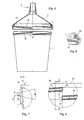
- the illustrated in Figure 1 flow cup for a paint spray gun contains a cup-shaped container 1 and a lid 2 can be placed on this, on which a connection part 3 for releasably securing the flow cup is formed on a paint spray gun.
- Both the container 1 and the lid 2 with the integrally formed connection part 3 are expediently produced as injection-molded parts made of plastic.
- the cup-shaped container 1 is filled in the position shown with the cover 2 removed. Subsequently, the cover 2 can be placed and used with its connection part 3 in the connection opening of an upside-down paint spray gun. For spraying, the paint spray gun can then be turned over so that the flow cup is located at the top of the paint spray gun.
- the flow cup e.g.
- a provided on the bottom 4 of the fluid cup - not shown - vent valve open or an initially closed venting channel by means of a pin or the like. To be pierced.
- a reclosable after use bleed valve or a reclosable vent there is the advantage that the flow cup can also be used to store not completely used up color.
- the connecting part 3 shown enlarged in Figures 2 and 3 consists of a molded on the conical cover 2 or otherwise integrally formed, tubular connecting piece 5, a front hollow cylindrical guide portion 6, an adjoining external thread 7 for screwing into a conventional internal thread and on the External thread 7 subsequent ringkeilelement 8 for a quick connection of the flow cup with the paint spray gun contains.
- the fferkeilelement 8 is formed by a groove 9 with a circumferentially oblique screw surface 10 which comes into engagement with a corresponding mating surface on a lug or projection of the paint spray gun.
- the wedge-shaped groove 9 with the screw 10 and the corresponding counter surface on the paint spray gun are so designed so that the flow cup can be attached to a rotation of the connecting piece 5 of about a quarter to half turn close to the paint spray gun.
- the connecting piece 5 is tightened for this purpose with its front end face 11 to a corresponding sealing surface within the paint spray gun.
- the flow cup can also be used for spray guns that have no matching to the fferkeilelement 8 connection, but a conventional connection with internal thread.
- an end-face stop face 12 for limiting the screw-in depth of the connecting piece 5 when using the external thread 7 for fastening the flow cup is provided on the connecting piece 5.
- the wedge-shaped groove 9 is arranged in a shoulder 13, which extends approximately over half the circumference of the connecting piece 5. The other half is free, so that a provided on the spray gun approach can get into the groove 9.
- the groove 9 is open at its front end, while it is closed at the rear end by a web 14 with a stop surface 15. This can prevent over-rotation of the quick release.
- paragraph 16 is provided with an annular support surface 17.
- paragraph 16 a known per se and therefore not shown filter can be used.
- the inner diameter of the shoulder 16 is slightly larger than the outer diameter of the hollow cylindrical guide portion 6.
- the shoulder 16 can also be used for stacking the lid 2. If a plurality of lids 2 are stacked on top of each other, the connecting piece 5 of the respective lower lid 2 engages with its hollow-cylindrical guide region 6 in the shoulder 16 of the respective upper lid 2 and is guided there.
- a four-speed quick-action thread shown in Figure 4 is provided with formed on the upper outer circumference of the container 1 external threads 18 and corresponding internal threads 19 on the cover 2.
- the quick-release thread is designed as a coarse thread with a pitch of 20 mm.
- the lid 2 can be screwed tightly to the container 1 by about a quarter turn.
- the four external threads 18 on the container 1 are uniformly distributed over the outer circumference and arranged according to Figure 6 such that the beginning of the 20 a thread 18 is located directly above the end 21 of the next thread 18.
- the distance x between the beginning 20 of the one thread and the end 21 of the other thread is 5 mm.
- the thread is further formed in the embodiment shown as a trapezoidal thread with a flank angle of 30 °.
- the quick-release thread can also be designed as a round thread, pointed thread or with another suitable profile.
- the outer diameter d of the external thread is between 100 and 110 mm, preferably 104.6 mm.
- the core diameter D of the external thread is between 90 and 105 mm, preferably 101.7 mm.
- the width b of the threads on the outside is between 1.1 and 1.3 mm, preferably 1.27 mm.
- a circumferential wedge-shaped sealing web 22 shown in Figure 5 is further formed, which defines a wedge-shaped annular groove 23 for receiving the upper container rim 24 between its outside and the inside of the lid 2.
- upwards wedge-shaped narrowing annular groove 23 of the upper container edge 24 is pressed when screwing the lid 2 to the outside to the inner wall of the lid 2, whereby a tight-fitting connection is formed.
- the sealing web 22 has a sufficiently high height to catch a color still present in the lid when the lid is removed and to prevent overflow into the internal thread.
- the invention is not limited to the embodiment described above and shown in the drawing.
- a collapsible insert for receiving the color are inserted.
Landscapes
- Nozzles (AREA)
- Closures For Containers (AREA)
- Table Devices Or Equipment (AREA)
- Details Or Accessories Of Spraying Plant Or Apparatus (AREA)
Description
- Die Erfindung betrifft einen Fließbecher für eine Farbspritzpistole nach dem Oberbegriff des Anspruchs 1. Ein derartiger Fließbecher ist aus der
US 2003/0213857 A1 bekannt. - Herkömmliche Fließbecher für Farbspritzpistolen weisen üblicherweise einen becherförmigen Behälter auf, an dessen Unterseite eine Öffnung mit einem Anschlussteil zur lösbaren Befestigung des Behälters auf der Oberseite der Farbspritzpistole vorgesehen ist. Das Anschlussteil besteht üblicherweise aus einem in den Behälterboden eingesetzten Anschlussstutzen, der ein Außengewinde zum Einschrauben in eine entsprechende Gewindeöffnung an der Oberseite der Farbspritzpistole aufweist. Der becherförmige Behälter wird auf seiner Oberseite in der Regel durch einen geeigneten Deckel verschlossen, der einen unerwünschten Austritt der Farbe verhindern soll. Allerdings ist die Herstellung derartiger Fließbecher mit den gesondert gefertigten und anschließend mit dem Behälter verbundenen Anschlussteilen relativ aufwändig und mit entsprechend hohen Kosten verbunden.
- Aus der
US 2003/0213857 A1 , die den nächstliegenden Stand der Technik bildet, ist ein Fließbecher für eine Farbspritzpistole mit einem becherförmigen Behälter, einem auf den Behälter aufsetzbaren Deckel und einem Anschlussstutzen mit einem Schraubkeilelement zum Anschluss des Fließbechers an der Farbspritzpistole bekannt. Bei diesem bekannten Fließbecher ist der Anschlussstutzen jedoch an dem becherförmigen Behälter angeformt. - In der
WO 02/085533 A1 - In der
WO 2004/037433 A1 , die einen Stand der Technik gemäß Art. 54 (3) EPÜ bildet, ist ein Fließbecher offenbart, der einen Behälter und einem auf den Behälter aufsetzbaren Deckel mit einem Anschlussstutzen enthält. An dem Anschlussstutzen ist ein Außengewindeabschnitt zum Schnellanschluss des Fließbechers an der Farbspritzpistole vorgesehen. - Aufgabe der Erfindung ist es, ein Fließbecher der eingangs genannten Art zu schaffen, der kostengünstig herstellbar ist und ohne zusätzlichen Adapter auch ohne Überdrehung des Schnellverschlusses schnell und einfach an einer Farbspritzpistole befestigt werden kann.
- Diese Aufgabe wird durch einen Fließbecher mit den Merkmalen des Anspruchs 1 gelöst. Zweckmäßige Ausgestaltungen und vorteilhafte Weiterbildungen der Erfindung sind Gegenstand der Unteransprüche.
- Ein wesentlicher Vorteil des erfindungsgemäßen Fließbechers besteht darin, dass er aus zwei einfach herstellbaren Teilen besteht. Über das am Deckel befindliche Schraubkeilelement kann der Fließbecher ohne zusätzliche Adapter einfach und schnell an der Farbspritzpistole befestigt und von dieser auch schnell wieder abgenommen werden. Durch die seitliche Anschlagfläche wird eine Überdrehung des Schnellverschlusses verhindert. Der kostengünstig herstellbare Fließbecher ist einfach befüllbar und kann entweder als Einmalbecher, zur Wiederverwendung oder auch zur Aufbewahrung restlicher Farben oder Lacke eingesetzt werden.
- In einer zweckmäßigen Ausgestaltung wird das Schraubkeilelement durch eine Nut mit einer in Umfangsrichtung schräg verlaufenden Schraubfläche gebildet, die in Eingriff mit einer entsprechenden Gegenfläche an einem Ansatz oder Vorsprung der Farbspritzpistole gelangt. Das Schraubkeilelement kann aber auch als keil- oder schraubförmiger Vorsprung ausgeführt sein, der in Eingriff mit einer entsprechenden Nut an der Farbspritzpistole gelangt.
- Eine weitere vorteilhafte Ausführung besteht darin, dass der Anschlussstutzen ein zusätzliches Gewinde zum Einschrauben in ein herkömmliches Innengewinde an einer Einlaßöffnung der Farbspritzpistole enthält. Dadurch kann der Fließbecher auch für Farbspritzpistolen verwendet werden, die keinen zu dem Schraubkeilelement passenden Schnellanschluss, jedoch einen herkömmlichen Anschluss mit Innengewinde aufweisen.
- Weitere Besonderheiten und Vorzüge der Erfindung ergeben sich aus der folgenden Beschreibung eines bevorzugten Ausführungsbeispiels anhand der Zeichnung. Es zeigen:
- Figur 1
- einen erfindungsgemäßen Fließbecher im Schnitt;
- Figur 2
- eine Schnittansicht entlang der Linie A-A von Figur 1;
- Figur 3
- eine Detailansicht des Bereichs X von Figur 1;
- Figur 4
- eine Ansicht des becherförmigen Behälters und des Deckels eines Fließbechers mit einem Schnellverschlussgewinde zum Aufschrauben des Deckels auf den Behälter;
- Figur 5
- eine Detailansicht des Bereichs Y von Figur 4;
- Figur 6
- eine Detailansicht des Bereichs W von Figur 4 und
- Figur 7
- eine Schnittansicht entlang der Linie A-A von Figur 4.
- Der in Figur 1 dargestellte Fließbecher für eine Farbspritzpistole enthält einen becherförmigen Behälter 1 und einen auf diesen aufsetzbaren Deckel 2, an dem ein Anschlussteil 3 zur lösbaren Befestigung des Fließbechers an einer Farbspritzpistole angeformt ist. Sowohl der Behälter 1 als auch der Deckel 2 mit dem angeformten Anschlussteil 3 sind zweckmäßigerweise als Spritzgussteile aus Kunststoff hergestellt. Der becherförmige Behälter 1 wird in der gezeigten Stellung mit abgenommenem Deckel 2 befüllt. Anschließend kann der Deckel 2 aufgesetzt und mit seinem Anschlußteil 3 in die Anschlussöffnung einer auf den Kopf gestellten Farbspritzpistole eingesetzt werden. Zum Spritzen kann dann die Farbspritzpistole umgedreht werden, so dass sich der Fließbecher an der Oberseite der Farbspritzpistole befindet. Um eine Entlüftung des Fließbechers zu ermöglichen, kann z.B. ein am Boden 4 des Fließbechers vorgesehenes - nicht dargestelltes - Entlüftungsventil geöffnet oder ein zunächst geschlossener Entlüftungskanal mit Hilfe eines Stifts oder dgl. durchstoßen werden. Durch ein nach Gebrauch wieder verschließbares Entlüftungsventil oder eine wieder verschließbare Entlüftungsöffnung ergibt sich der Vorteil, dass der Fließbecher auch zur Aufbewahrung nicht vollständig aufgebrauchter Farbe verwendet werden kann.
- Der in den Figuren 2 und 3 vergrößert dargestellte Anschlußteil 3 besteht aus einem an dem konischen Deckel 2 angespritzten oder anderweitig angeformten, rohrförmigen Anschlussstutzen 5, der einen vorderen hohlzylindrischen Führungsbereich 6, ein daran anschließendes Außengewinde 7 zum Einschrauben in ein konventionelles Innengewinde und ein an das Außengewinde 7 anschließendes Schraubkeilelement 8 für eine Schnellverbindung des Fließbechers mit der Farbspritzpistole enthält. Bei der gezeigten Ausführung wird das Schraubkeilelement 8 durch eine Nut 9 mit einer in Umfangsrichtung schräg verlaufenden Schraubfläche 10 gebildet, die in Eingriff mit einer entsprechenden Gegenfläche an einem Ansatz oder Vorsprung der Farbspritzpistole gelangt. Die keilförmige Nut 9 mit der Schraubfläche 10 und die entsprechende Gegenfläche an der Farbspritzpistole sind so ausgebildet, dass der Fließbecher bereits bei einer Drehung des Anschlussstutzen 5 von etwa einer viertel bis halben Umdrehung dicht an der Farbspritzpistole befestigt werden kann. Der Anschlussstutzen 5 wird hierzu mit seiner vorderen Stirnfläche 11 an eine entsprechende Dichtfläche innerhalb der Farbspritzpistole angezogen. Über das zusätzliche Außengewinde 7 kann der Fließbecher auch für Farbspritzpistolen verwendet werden, die keinen zu dem Schraubkeilelement 8 passenden Anschluss, jedoch einen herkömmlichen Anschluss mit Innengewinde aufweisen. Zwischen dem Außengewinde 7 und dem Schraubkeilelement 8 ist an dem Anschlussstutzen 5 eine stirnseitige Anschlagfläche 12 zur Begrenzung der Einschraubtiefe des Anschlussstutzen 5 bei der Verwendung des Außengewindes 7 zur Befestigung des Fließbechers vorgesehen.
- Wie besonders aus Figur 2 hervorgeht, ist die keilförmige Nut 9 in einer Schulter 13 angeordnet, die etwa über die Hälfte des Umfangs des Anschlussstutzens 5 verläuft. Die andere Hälfte ist frei, so dass ein an der Farbspritzpistole vorgesehener Ansatz in die Nut 9 gelangen kann. Die Nut 9 ist an ihrem vorderen Ende offen, während sie am hinteren Ende durch einen Steg 14 mit einer Anschlagfläche 15 geschlossen ist. Dadurch kann ein Überdrehen des Schnellverschlusses verhindert werden.
- Innerhalb des Anschlussstutzens 5 ist ein in Figur 3 gezeigter Absatz 16 mit einer ringförmigen Auflagefläche 17 vorgesehen. In den Absatz 16 ist ein an sich bekannter und daher nicht dargestellter Filter einsetzbar. Der Innendurchmesser des Absatzes 16 ist etwas größer als der Außendurchmesser des hohlzylindrischen Führungsbereichs 6. Dadurch kann der Absatz 16 auch zum Stapeln der Deckel 2 verwendet werden. Wenn mehrere Deckel 2 aufeinander gestapelt sind, greift der Anschlussstutzen 5 des jeweils unteren Deckels 2 mit seinem hohlzylindrischen Führungsbereich 6 in den Absatz 16 des jeweils oberen Deckels 2 ein und wird dort geführt.
- Zur dichten Verbindung des Behälters 1 und des Deckels 2 ist ein in Figur 4 dargestelltes viergängiges Schnellverschlussgewinde mit am oberen Außenumfang des Behälters 1 angeformten Außengewindegängen 18 und dazu korrespondierenden Innengewindegängen 19 an dem Deckel 2 vorgesehen. Das Schnellverschlussgewinde ist als Steilgewinde mit einer Steigung von 20 mm ausgeführt. Dadurch kann der Deckel 2 durch etwa eine viertel Drehung fest mit dem Behälter 1 verschraubt werden. Die vier Außengewindegänge 18 am Behälter 1 sind gleichmäßig über den Außenumfang verteilt und gemäß Figur 6 derart angeordnet, dass der Anfang 20 des einen Gewindegangs 18 direkt über dem Ende 21 des nächsten Gewindegangs 18 liegt. Der Abstand x zwischen dem Anfang 20 des einen Gewindegangs und dem Ende 21 des anderen Gewindegangs beträgt 5 mm. Wie aus Figur 7 hervorgeht, ist das Gewinde bei der gezeigten Ausführung ferner als Trapezgewinde mit einem Flankenwinkel von 30° ausgebildet. Das Schnellverschlussgewinde kann aber auch als Rundgewinde, Spitzgewinde oder mit einen anderen geeigneten Profil ausgeführt sein. Der Außendurchmesser d des Außengewindes beträgt zwischen 100 und 110 mm, vorzugsweise 104,6 mm. Der Kerndurchmesser D des Außengewindes beträgt zwischen 90 und 105 mm, vorzugsweise 101,7 mm. Die Breite b der Gewindegänge an der Außenseite beträgt zwischen 1,1 und 1,3 mm, vorzugsweise 1,27 mm.
- An der Innenseite des Deckels 2 ist ferner ein in Figur 5 gezeigter umlaufender keilförmiger Dichtungssteg 22 angeformt, der zwischen seiner Außenseite und der Innenseite des Deckels 2 eine keilförmige Ringnut 23 für die Aufnahme des oberen Behälterrands 24 begrenzt. Durch die sich in Figur 5 nach oben keilförmig verengende Ringnut 23 wird der obere Behälterrand 24 beim Aufschrauben des Deckels 2 nach außen an die Innenwand des Deckels 2 angedrückt, wodurch eine dicht schließende Verbindung entsteht. Der Dichtungssteg 22 weist eine ausreichend große Höhe auf, um eine noch im Deckel befindliche Farbe beim Ablegen des Deckels aufzufangen und ein Überlaufen in das Innengewinde zu verhindern.
- Die Erfindung ist nicht auf das vorstehend beschriebene und der Zeichnung dargestellte Ausführungsbeispiel beschränkt. So kann z.B. in den Behälter auch ein zusammenfaltbarer Einsatz für die Aufnahme der Farbe eingelegt werden.
Claims (11)
- Fließbecher für eine Farbspritzpistole mit einem becherförmigen Behälter (1), einem auf den Behälter (1) aufsetzbaren Deckel (2) und einem Anschlußteil (3), der zur Befestigung des Fließbechers an der Farbspritzpistole aus einem Anschlussstutzen (5) mit einem Schraubkeilelement (8) zum unmittelbaren Schnellanschluß des Fließbechers an der Farbspritzpistole besteht, dadurch gekennzeichnet, dass der Anschlussstutzen (5) direkt an dem Deckel (2) angeformt ist und eine seitliche Anschlagfläche (15) zur Begrenzung der Einschraubtiefe bei Verwendung des Schraubkeilelements (8) für die Befestigung des Fließbechers enthält.
- Fließbecher nach Anspruch 1, dadurch gekennzeichnet, dass das Schraubkeilelement (8) durch eine Nut (9) mit einer in Umfangsrichtung schräg verlaufenden Schraubfläche (10) gebildet wird.
- Fließbecher nach Anspruch 1 oder 2, dadurch gekennzeichnet, dass der Anschlussstutzen (5) ein zusätzliches Gewinde (7) enthält.
- Fließbecher nach Anspruch 3, dadurch gekennzeichnet, dass der Anschlussstutzen (5) eine stirnseitige Anschlagfläche (12) zur Begrenzung der Einschraubtiefe bei Verwendung des Gewindes (7) für die Befestigung des Fließbechers enthält.
- Fließbecher nach einem der Ansprüche 1 bis 4, dadurch gekennzeichnet, dass im Inneren des Anschlussstutzens (5) ein Absatz (16) mit einer Auflagefläche (17) vorgesehen ist.
- Fließbecher nach einem der Ansprüche 1 bis 5, dadurch gekennzeichnet, dass der Behälter (1) und der Deckel (2) über ein Schnellverschlussgewinde (18, 19) dicht miteinander verbindbar sind.
- Fließbecher nach Anspruch 6, dadurch gekennzeichnet, dass das Schnellverschlussgewinde (18, 19) ein viergängiges Steilgewinde mit Außengewindegängen (18) am oberen Außenumfang des Behälters (1) und dazu korrespondierenden Innengewindegängen (19) an der Innenseite des Deckels (2) ist.
- Fließbecher nach Anspruch 6 oder 7, dadurch gekennzeichnet, dass das Schnellverschlussgewinde (18, 19) eine Steigung von 20 mm aufweist.
- Fließbecher nach einem der Ansprüche 1 bis 8, dadurch gekennzeichnet, dass an der Innenseite des Deckels (2) ein keilförmiger Dichtungssteg (22) angeformt ist, der zwischen seiner Außenseite und der Innenseite des Deckels (2) eine keilförmige Ringnut (23) für die Aufnahme des oberen Behälterrands (24) begrenzt.
- Fließbecher nach Anspruch 9, dadurch gekennzeichnet, dass der Dichtungssteg (22) eine ausreichend große Höhe zum Auffangen im Deckel (2) befindlicher Farbe beim Ablegen des Deckels (2) aufweist.
- Fließbecher nach einem der Ansprüche 1 bis 10, dadurch gekennzeichnet, dass in den Behälter (1) ein Einsatz einlegbar ist.
Priority Applications (2)
| Application Number | Priority Date | Filing Date | Title |
|---|---|---|---|
| EP07121957A EP1902786B1 (de) | 2004-01-22 | 2005-01-18 | Fließbecher für eine Farbspritzpistole |
| PL05701010T PL1708823T3 (pl) | 2004-01-22 | 2005-01-18 | Kubek opadowy dla pistoletu do malowania natryskowego |
Applications Claiming Priority (2)
| Application Number | Priority Date | Filing Date | Title |
|---|---|---|---|
| DE102004003438A DE102004003438A1 (de) | 2004-01-22 | 2004-01-22 | Fließbecher für eine Farbspritzpistole |
| PCT/EP2005/000437 WO2005070558A1 (de) | 2004-01-22 | 2005-01-18 | Fliessbecher für eine farbspritzpistole |
Related Child Applications (1)
| Application Number | Title | Priority Date | Filing Date |
|---|---|---|---|
| EP07121957A Division EP1902786B1 (de) | 2004-01-22 | 2005-01-18 | Fließbecher für eine Farbspritzpistole |
Publications (2)
| Publication Number | Publication Date |
|---|---|
| EP1708823A1 EP1708823A1 (de) | 2006-10-11 |
| EP1708823B1 true EP1708823B1 (de) | 2008-01-16 |
Family
ID=34800936
Family Applications (2)
| Application Number | Title | Priority Date | Filing Date |
|---|---|---|---|
| EP05701010A Expired - Lifetime EP1708823B1 (de) | 2004-01-22 | 2005-01-18 | Fliessbecher für eine farbspritzpistole |
| EP07121957A Expired - Lifetime EP1902786B1 (de) | 2004-01-22 | 2005-01-18 | Fließbecher für eine Farbspritzpistole |
Family Applications After (1)
| Application Number | Title | Priority Date | Filing Date |
|---|---|---|---|
| EP07121957A Expired - Lifetime EP1902786B1 (de) | 2004-01-22 | 2005-01-18 | Fließbecher für eine Farbspritzpistole |
Country Status (12)
| Country | Link |
|---|---|
| US (1) | US8444067B2 (de) |
| EP (2) | EP1708823B1 (de) |
| JP (1) | JP4448518B2 (de) |
| CN (1) | CN100430150C (de) |
| AT (1) | ATE383910T1 (de) |
| AU (1) | AU2005205899B2 (de) |
| CA (1) | CA2552390C (de) |
| DE (4) | DE202004021702U1 (de) |
| ES (1) | ES2300974T3 (de) |
| PL (1) | PL1708823T3 (de) |
| TW (1) | TWI303587B (de) |
| WO (1) | WO2005070558A1 (de) |
Cited By (6)
| Publication number | Priority date | Publication date | Assignee | Title |
|---|---|---|---|---|
| US9327301B2 (en) | 2008-03-12 | 2016-05-03 | Jeffrey D. Fox | Disposable spray gun cartridge |
| US9333519B2 (en) | 2010-12-02 | 2016-05-10 | Sata Gmbh & Co. Kg | Spray gun and accessories |
| US9409197B2 (en) | 2013-12-18 | 2016-08-09 | Sata Gmbh & Co. Kg | Air nozzle closure for a spray gun |
| USD768820S1 (en) | 2014-09-03 | 2016-10-11 | Sata Gmbh & Co. Kg | Paint spray gun with pattern |
| USD770593S1 (en) | 2014-07-31 | 2016-11-01 | Sata Gmbh & Co. Kg | Paint spray gun |
| US9533317B2 (en) | 2009-07-08 | 2017-01-03 | Sata Gmbh & Co. Kg | Paint spray gun |
Families Citing this family (73)
| Publication number | Priority date | Publication date | Assignee | Title |
|---|---|---|---|---|
| US7083119B2 (en) | 2003-09-25 | 2006-08-01 | 3M Innovative Properties Company | Security clip for spray gun connector |
| US8127963B2 (en) | 2004-12-16 | 2012-03-06 | Saint-Gobain Abrasives, Inc. | Liquid container system for a spray gun |
| US11040360B2 (en) * | 2006-06-20 | 2021-06-22 | Saint-Gobain Abrasives, Inc. | Liquid supply assembly |
| DE502007000825D1 (de) | 2006-12-05 | 2009-07-16 | Sata Gmbh & Co Kg | Belüftung für den Fließbecher einer Farbspritzpistole |
| DE102007039106B4 (de) | 2007-08-18 | 2022-06-09 | Sata Gmbh & Co. Kg | Farbbehälter für eine Spritzpistole, mit einem Anschlussteil zur Verbindung des Farbbehälters an eine Spritzpistole und Farbspritzeinrichtung |
| DE202007011604U1 (de) * | 2007-08-18 | 2009-01-02 | Sata Gmbh & Co. Kg | Anschlussteil zur Verbindung einer Materialzuführungseinrichtung an eine Spritzpistole |
| EP2185302B1 (de) * | 2007-09-10 | 2020-05-13 | Weir Minerals Australia Ltd | Verfahren und vorrichtung zur herstellung eines gusskörpers |
| DE202008014389U1 (de) | 2008-10-29 | 2010-04-08 | Sata Gmbh & Co. Kg | Fließbecher für eine Farbspritzpistole |
| DE102009011200A1 (de) * | 2009-03-04 | 2010-09-09 | Büttner, Dirk | Befestigungssystem mit einer Schraubkeilverbindung. Farbspritzpistole und Adapter für eine Farbspritzpistole |
| DE102009034715A1 (de) | 2009-07-24 | 2011-01-27 | Martin Ruda | Spritzgusswerkzeug, Verfahren zum Spritzgießen eines Spritzgussbauteils sowie Verschluss- und/oder Anschlusseinrichtung eines Spritzpistolenfarbbechers |
| DE202010007355U1 (de) | 2010-05-28 | 2011-10-20 | Sata Gmbh & Co. Kg | Düsenkopf für eine Spritzvorrichtung |
| US20120000992A1 (en) * | 2010-07-01 | 2012-01-05 | Hsien-Chao Shih | Paint cup structure of paintball gun |
| WO2012154623A2 (en) | 2011-05-06 | 2012-11-15 | Saint-Gobain Abrasives, Inc. | Paint cup assembly support structure |
| CN107537707B (zh) | 2011-06-30 | 2021-09-03 | 萨塔有限两合公司 | 喷枪、喷射介质引导单元、盖子、底座本体及相关方法 |
| WO2013101946A1 (en) | 2011-12-30 | 2013-07-04 | Saint-Gobain Abrasives, Inc. | Convertible paint cup assembly with air inlet valve |
| CA155474S (en) | 2013-09-27 | 2015-08-27 | Sata Gmbh & Co Kg | Spray gun |
| MX2016007249A (es) | 2013-12-05 | 2017-01-05 | 3M Innovative Properties Co | Contenedor para dispositivo atomizador. |
| CN105289870B (zh) | 2014-07-31 | 2019-09-24 | 萨塔有限两合公司 | 喷枪的制造方法、喷枪、喷枪本体以及盖 |
| USD758537S1 (en) | 2014-07-31 | 2016-06-07 | Sata Gmbh & Co. Kg | Paint spray gun rear portion |
| DE102015006484A1 (de) | 2015-05-22 | 2016-11-24 | Sata Gmbh & Co. Kg | Düsenanordnung für eine Spritzpistole, insbesondere Farbspritzpistole und Spritzpistole, insbesondere Farbspritzpistole |
| US10576490B2 (en) | 2015-07-08 | 2020-03-03 | 3M Innovative Properties Company | Spray gun cups, receptacles, and methods of use |
| USD792556S1 (en) | 2015-07-08 | 2017-07-18 | 3M Innovative Properties Company | Spray gun cup receptacle |
| EP3135385B2 (de) * | 2015-08-25 | 2022-02-09 | Andreas Massold | Deckel für einen flüssigkeitsbehälter für eine spritzpistole |
| DE102015016474A1 (de) | 2015-12-21 | 2017-06-22 | Sata Gmbh & Co. Kg | Luftkappe und Düsenanordnung für eine Spritzpistole und Spritzpistole |
| PL3402606T5 (pl) | 2016-01-15 | 2026-01-26 | 3M Innovative Properties Company | Układ złączy do ręcznych pistoletów natryskowych |
| AU2017207351B2 (en) | 2016-01-15 | 2019-10-31 | 3M Innovative Properties Company | Modular spray gun lid assemblies and methods of design and use |
| USD793531S1 (en) | 2016-03-24 | 2017-08-01 | 3M Innovative Properties Company | Spray gun cup receptacle |
| AU2017207352B2 (en) | 2016-01-15 | 2019-09-12 | 3M Innovative Properties Company | Spray gun cups, receptacles, and methods of use |
| EP4309867A3 (de) | 2016-01-15 | 2024-03-27 | 3M Innovative Properties Company | Weitmundiger flüssigkeitsverbinder für handspritzpistolen |
| US10689165B2 (en) | 2016-01-15 | 2020-06-23 | 3M Innovative Properties Company | Reservoir systems for hand-held spray guns and methods of use |
| USD793530S1 (en) | 2016-03-24 | 2017-08-01 | 3M Innovative Properties Company | Lid for spray gun cup |
| USD811525S1 (en) | 2016-03-24 | 2018-02-27 | 3M Innovative Properties Company | Retention collar for spray gun cup |
| US11638924B2 (en) | 2016-01-15 | 2023-05-02 | 3M Innovative Properties Company | Spray gun cups, receptacles, lids, and methods of use |
| CN205966208U (zh) | 2016-08-19 | 2017-02-22 | 萨塔有限两合公司 | 风帽组件以及喷枪 |
| CN205995666U (zh) | 2016-08-19 | 2017-03-08 | 萨塔有限两合公司 | 喷枪及其扳机 |
| USD810862S1 (en) * | 2016-12-12 | 2018-02-20 | 3M Innovative Properties Company | Spray gun liquid containment device |
| USD810235S1 (en) * | 2016-12-12 | 2018-02-13 | 3M Innovative Properties Company | Spray gun liquid containment device |
| USD810866S1 (en) * | 2016-12-12 | 2018-02-20 | 3M Innovative Properties Company | Spray gun liquid containment device |
| USD810863S1 (en) * | 2016-12-12 | 2018-02-20 | 3M Innovative Properties Company | Spray gun liquid containment device |
| USD813985S1 (en) * | 2016-12-12 | 2018-03-27 | 3M Innovative Properties Company | Spray gun liquid containment device |
| USD810868S1 (en) * | 2016-12-12 | 2018-02-20 | 3M Innovative Properties Company | Spray gun liquid containment device |
| USD810870S1 (en) | 2016-12-12 | 2018-02-20 | 3M Innovative Properties Company | Shaker core |
| USD810869S1 (en) * | 2016-12-12 | 2018-02-20 | 3M Innovative Properties Company | Spray gun liquid containment device |
| USD810865S1 (en) * | 2016-12-12 | 2018-02-20 | 3M Innovative Properties Company | Spray gun liquid containment device |
| ES2952739T3 (es) * | 2016-12-12 | 2023-11-03 | 3M Innovative Properties Company | Sistemas de depósito para pistolas rociadoras sostenidas a mano |
| USD810864S1 (en) * | 2016-12-12 | 2018-02-20 | 3M Innovative Properties Company | Spray gun liquid containment device |
| USD804613S1 (en) | 2016-12-12 | 2017-12-05 | 3M Innovative Properties Company | Spray gun nozzle |
| USD815248S1 (en) * | 2016-12-12 | 2018-04-10 | 3M Innovative Properties Company | Spray gun liquid containment device |
| USD810867S1 (en) * | 2016-12-12 | 2018-02-20 | 3M Innovative Properties Company | Spray gun liquid containment device |
| USD812716S1 (en) | 2016-12-12 | 2018-03-13 | 3M Innovative Properties Company | Liquid containment device plug |
| USD810872S1 (en) | 2016-12-12 | 2018-02-20 | 3M Innovative Properties Company | Shaker core |
| USD833571S1 (en) | 2016-12-12 | 2018-11-13 | 3M Innovative Properties Company | Spray gun |
| USD810871S1 (en) | 2016-12-12 | 2018-02-20 | 3M Innovative Properties Company | Shaker core |
| USD817443S1 (en) * | 2016-12-12 | 2018-05-08 | 3M Innovative Properties Company | Spray gun liquid containment device |
| USD804614S1 (en) | 2016-12-12 | 2017-12-05 | 3M Innovative Properties Company | Adaptor for securing liquid containment device to spray gun |
| CN106423612A (zh) * | 2016-12-28 | 2017-02-22 | 王武恩 | 一次性内胆隔离式免洗喷枪喷壶 |
| US12558698B2 (en) | 2017-07-14 | 2026-02-24 | 3M Innovative Properties Company | Fluid delivery assembly for a spray gun |
| US10710105B2 (en) * | 2017-10-31 | 2020-07-14 | Zhejiang Rongpeng Air Tools Co., Ltd. | Disposable cleaning-free paint pot |
| CN112533705B (zh) | 2018-08-01 | 2023-07-04 | 萨塔有限两合公司 | 喷枪的喷嘴组、喷枪系统、制造喷嘴模块的方法、为上漆任务从喷嘴组选出喷嘴模块的方法、选择系统和计算机程序产品 |
| DE102018118738A1 (de) | 2018-08-01 | 2020-02-06 | Sata Gmbh & Co. Kg | Grundkörper für eine Spritzpistole, Spritzpistolen, Spritzpistolen-Set, Verfahren zur Herstellung eines Grundkörpers für eine Spritzpistole und Verfahren zum Umrüsten einer Spritzpistole |
| DE102018118737A1 (de) | 2018-08-01 | 2020-02-06 | Sata Gmbh & Co. Kg | Düse für eine Spritzpistole, Düsensatz für eine Spritzpistole, Spritzpistolen und Verfahren zur Herstellung einer Düse für eine Spritzpistole |
| DE102018122004A1 (de) | 2018-09-10 | 2020-03-12 | Sata Gmbh & Co. Kg | Lackierpistole, Materialauftragssystem und Verfahren zu dessen Betrieb |
| USD918340S1 (en) * | 2019-05-01 | 2021-05-04 | Tony ZHENG | Paint cup |
| USD916232S1 (en) * | 2019-06-04 | 2021-04-13 | Qingdao Hanbo Plastic Technology Co., Ltd. | Lid for spray gun |
| USD916231S1 (en) * | 2019-06-04 | 2021-04-13 | Qingdao Hanbo Plastic Technology Co., Ltd. | Lid for spray gun |
| DE102020106172A1 (de) | 2020-03-06 | 2021-09-09 | Sata Gmbh & Co. Kg | Spritzpistole, insbesondere druckluftzerstäubende Farbspritzpistole, insbesondere handgeführte druckluftzerstäubende Farbspritzpistole |
| DE102020109913A1 (de) | 2020-04-08 | 2021-10-14 | Sata Gmbh & Co. Kg | Farbbecher aus natürlichem Faserstoff |
| AU2021305045B2 (en) * | 2020-07-06 | 2024-05-23 | Ppg Industries Ohio, Inc. | Adapter for connecting a fluid reservoir can to a fluid applicator |
| DE102020120228A1 (de) | 2020-07-31 | 2022-02-03 | Sata Gmbh & Co. Kg | Fließbecher für eine Spritzpistole mit einer Belüftungseinrichtung |
| DE102020123769A1 (de) | 2020-09-11 | 2022-03-17 | Sata Gmbh & Co. Kg | Dichtelement zum Abdichten eines Übergangs zwischen einem Grundkörper einer Spritzpistole und einem Anbauteil einer Spritzpistole, Anbauteil, insbesondere Farbdüsenanordnung, für eine Spritzpistole und Spritzpistole, insbesondere Farbspritzpistole |
| USD1046076S1 (en) | 2021-10-15 | 2024-10-08 | Sata Gmbh & Co. Kg | Spray gun |
| US20240082861A1 (en) * | 2022-09-08 | 2024-03-14 | Fairway Electronic Co., Ltd. | Foam spray can and quick release structure for foam spray can |
| DE102023107368A1 (de) * | 2023-03-23 | 2024-09-26 | Sata Gmbh & Co. Kg | Fließbecher für eine Farbspritzpistole mit Schraubdeckel und Schraubdeckel oder Materialbehälter eines solchen Fließbechers |
Family Cites Families (18)
| Publication number | Priority date | Publication date | Assignee | Title |
|---|---|---|---|---|
| DE3402097A1 (de) * | 1984-01-21 | 1985-08-01 | Sata-Farbspritztechnik GmbH, 7140 Ludwigsburg | Farbbecher fuer eine farbspritzpistole |
| CN2034876U (zh) * | 1988-05-03 | 1989-03-29 | 贾杰臣 | 一种喷洒枪 |
| DE8902223U1 (de) * | 1989-02-24 | 1989-04-06 | SATA - Farbspritztechnik GmbH & Co., 7140 Ludwigsburg | Farbspritzpistole |
| JPH0474552A (ja) * | 1990-07-13 | 1992-03-09 | Chiron Werke Gmbh & Co Kg | スプレーガン |
| EP1961488B2 (de) | 1997-01-24 | 2021-02-24 | 3M Company | Vorrichtung zum Sprühen von Flüssigkeiten und Einwegbehälter und -Auskleidungen die dafür geeignet sind |
| GB9701447D0 (en) | 1997-01-24 | 1997-03-12 | Minnesota Mining & Mfg | Container |
| US6820824B1 (en) * | 1998-01-14 | 2004-11-23 | 3M Innovative Properties Company | Apparatus for spraying liquids, disposable containers and liners suitable for use therewith |
| US6536687B1 (en) | 1999-08-16 | 2003-03-25 | 3M Innovative Properties Company | Mixing cup adapting assembly |
| GB0110025D0 (en) * | 2001-04-24 | 2001-06-13 | 3M Innovative Properties Co | Improvements in or relating to liquid spraying apparatus |
| CN2497873Y (zh) * | 2001-05-28 | 2002-07-03 | 沈文龙 | 喷漆枪上置式装料罐 |
| EP1446232B1 (de) * | 2001-11-14 | 2005-05-04 | Martin Ruda | Spritzpistolenbecher mit fester einlage |
| DE10205831A1 (de) * | 2002-02-13 | 2003-08-28 | Sata Farbspritztechnik | Farbspritzpistole |
| US7101695B2 (en) * | 2002-03-01 | 2006-09-05 | Szu-Yi Chou | Method of producing transglutaminase having broad substrate activity |
| GB0224698D0 (en) | 2002-10-24 | 2002-12-04 | 3M Innovative Properties Co | Easy clean spray gun |
| US6712292B1 (en) * | 2003-06-10 | 2004-03-30 | Illinois Tool Works Inc. | Adjustable adapter for gravity-feed paint sprayer |
| US7380680B2 (en) * | 2004-01-16 | 2008-06-03 | Illinois Tool Works Inc. | Fluid supply assembly |
| US7165732B2 (en) * | 2004-01-16 | 2007-01-23 | Illinois Tool Works Inc. | Adapter assembly for a fluid supply assembly |
| US7036752B1 (en) * | 2005-06-20 | 2006-05-02 | Shin Kuei Hsiang | Connection of cup and paint sprayer |
-
2004
- 2004-01-22 DE DE202004021702U patent/DE202004021702U1/de not_active Expired - Lifetime
- 2004-01-22 DE DE102004003438A patent/DE102004003438A1/de not_active Ceased
-
2005
- 2005-01-18 JP JP2006550013A patent/JP4448518B2/ja not_active Expired - Fee Related
- 2005-01-18 US US10/597,159 patent/US8444067B2/en active Active
- 2005-01-18 AT AT05701010T patent/ATE383910T1/de active
- 2005-01-18 DE DE502005002565T patent/DE502005002565D1/de not_active Expired - Lifetime
- 2005-01-18 ES ES05701010T patent/ES2300974T3/es not_active Expired - Lifetime
- 2005-01-18 CA CA2552390A patent/CA2552390C/en not_active Expired - Lifetime
- 2005-01-18 WO PCT/EP2005/000437 patent/WO2005070558A1/de not_active Ceased
- 2005-01-18 DE DE502005006971T patent/DE502005006971D1/de not_active Expired - Lifetime
- 2005-01-18 EP EP05701010A patent/EP1708823B1/de not_active Expired - Lifetime
- 2005-01-18 PL PL05701010T patent/PL1708823T3/pl unknown
- 2005-01-18 CN CNB200580002916XA patent/CN100430150C/zh not_active Expired - Fee Related
- 2005-01-18 AU AU2005205899A patent/AU2005205899B2/en not_active Ceased
- 2005-01-18 EP EP07121957A patent/EP1902786B1/de not_active Expired - Lifetime
- 2005-01-19 TW TW094101512A patent/TWI303587B/zh not_active IP Right Cessation
Cited By (7)
| Publication number | Priority date | Publication date | Assignee | Title |
|---|---|---|---|---|
| US9327301B2 (en) | 2008-03-12 | 2016-05-03 | Jeffrey D. Fox | Disposable spray gun cartridge |
| US9533317B2 (en) | 2009-07-08 | 2017-01-03 | Sata Gmbh & Co. Kg | Paint spray gun |
| US9333519B2 (en) | 2010-12-02 | 2016-05-10 | Sata Gmbh & Co. Kg | Spray gun and accessories |
| US9409197B2 (en) | 2013-12-18 | 2016-08-09 | Sata Gmbh & Co. Kg | Air nozzle closure for a spray gun |
| USD770593S1 (en) | 2014-07-31 | 2016-11-01 | Sata Gmbh & Co. Kg | Paint spray gun |
| USD798419S1 (en) | 2014-07-31 | 2017-09-26 | Sata Gmbh & Co. Kg | Paint spray gun |
| USD768820S1 (en) | 2014-09-03 | 2016-10-11 | Sata Gmbh & Co. Kg | Paint spray gun with pattern |
Also Published As
| Publication number | Publication date |
|---|---|
| US8444067B2 (en) | 2013-05-21 |
| CA2552390C (en) | 2011-06-28 |
| ES2300974T3 (es) | 2008-06-16 |
| DE102004003438A1 (de) | 2005-08-18 |
| CN1909971A (zh) | 2007-02-07 |
| CA2552390A1 (en) | 2005-08-04 |
| EP1708823A1 (de) | 2006-10-11 |
| AU2005205899B2 (en) | 2009-03-26 |
| PL1708823T3 (pl) | 2008-06-30 |
| EP1902786B1 (de) | 2009-03-25 |
| DE502005006971D1 (de) | 2009-05-07 |
| US20090014557A1 (en) | 2009-01-15 |
| EP1902786A1 (de) | 2008-03-26 |
| HK1100405A1 (zh) | 2007-09-21 |
| ATE383910T1 (de) | 2008-02-15 |
| JP4448518B2 (ja) | 2010-04-14 |
| TW200533422A (en) | 2005-10-16 |
| AU2005205899A1 (en) | 2005-08-04 |
| JP2007518555A (ja) | 2007-07-12 |
| DE202004021702U1 (de) | 2010-05-20 |
| DE502005002565D1 (de) | 2008-03-06 |
| WO2005070558A1 (de) | 2005-08-04 |
| CN100430150C (zh) | 2008-11-05 |
| TWI303587B (en) | 2008-12-01 |
Similar Documents
| Publication | Publication Date | Title |
|---|---|---|
| EP1902786B1 (de) | Fließbecher für eine Farbspritzpistole | |
| EP2340126B1 (de) | Fliessbecher für eine farbspritzpistole | |
| EP2027931B1 (de) | Anschlussteil zur Verbindung einer Materialzuführungseinrichtung an eine Spritzpistole | |
| EP1793933B1 (de) | Verwendung eines fliessbechers für eine farbspritzpistole | |
| DE102007039106B4 (de) | Farbbehälter für eine Spritzpistole, mit einem Anschlussteil zur Verbindung des Farbbehälters an eine Spritzpistole und Farbspritzeinrichtung | |
| DE10397013B4 (de) | Einwandiger Spritzpistolenbecher | |
| EP1708822B1 (de) | Farbbechersystem für eine farbspritzpistole | |
| DE102004007733B4 (de) | Fließbecher für eine Farbspritzpistole | |
| DE2746517C3 (de) | Spritzeinrichtung | |
| DE202004003116U1 (de) | Fließbecher für eine Farbspritzpistole | |
| DE20321623U1 (de) | Spritzpistole mit eingebautem Schnellverbinder für einen Farbtank | |
| DE29909950U1 (de) | Spritzpistolenbehälter | |
| DE202011100846U1 (de) | Einfüllstutzen für einen Harnstoffbehälter und einen damit versehenen Harnstoffbehälter | |
| DE10315426A1 (de) | Spritzpistolenbecher und Verfahren zum Herstellen eines Deckels | |
| DE202004003376U1 (de) | Farbbechersystem für eine Farbspritzpistole | |
| DE4208968A1 (de) | Mehrteiliger verschluss fuer gefaesse mit kegelfoermig auseinanderlaufender muendung | |
| EP4132720A1 (de) | Farbbecher aus natürlichem faserstoff | |
| DE19730645C1 (de) | Zwei-Komponenten-Spritzkartusche | |
| DE2725121C2 (de) | Spundlochverschluß für Fässer, Dosen o.dgl. | |
| DE202004014049U1 (de) | Fließbecher für eine Farbspritzpistole | |
| DE3448408C2 (de) | Flüssigkeitszerstäuber | |
| DE20120040U1 (de) | Palettenbehälter mit einem Kunststoffbehälter, in dem ein Kontaktelement für die Ableitung elektrostatischer Ladungen angeordnet ist | |
| DE202018104525U1 (de) | Deckel mit Ausgießer | |
| WO2012119173A2 (de) | Mehrteiliger einfüllstutzen für einen tank und tank mit einem solchen | |
| DE7930072U1 (de) | Gartenspritze |
Legal Events
| Date | Code | Title | Description |
|---|---|---|---|
| PUAI | Public reference made under article 153(3) epc to a published international application that has entered the european phase |
Free format text: ORIGINAL CODE: 0009012 |
|
| 17P | Request for examination filed |
Effective date: 20060822 |
|
| AK | Designated contracting states |
Kind code of ref document: A1 Designated state(s): AT BE BG CH CY CZ DE DK EE ES FI FR GB GR HU IE IS IT LI LT LU MC NL PL PT RO SE SI SK TR |
|
| 17Q | First examination report despatched |
Effective date: 20061201 |
|
| DAX | Request for extension of the european patent (deleted) | ||
| RAP1 | Party data changed (applicant data changed or rights of an application transferred) |
Owner name: SATA GMBH & CO. KG |
|
| GRAP | Despatch of communication of intention to grant a patent |
Free format text: ORIGINAL CODE: EPIDOSNIGR1 |
|
| GRAS | Grant fee paid |
Free format text: ORIGINAL CODE: EPIDOSNIGR3 |
|
| GRAA | (expected) grant |
Free format text: ORIGINAL CODE: 0009210 |
|
| AK | Designated contracting states |
Kind code of ref document: B1 Designated state(s): AT BE BG CH CY CZ DE DK EE ES FI FR GB GR HU IE IS IT LI LT LU MC NL PL PT RO SE SI SK TR |
|
| REG | Reference to a national code |
Ref country code: GB Ref legal event code: FG4D Free format text: NOT ENGLISH |
|
| REG | Reference to a national code |
Ref country code: CH Ref legal event code: EP |
|
| REG | Reference to a national code |
Ref country code: IE Ref legal event code: FG4D Free format text: LANGUAGE OF EP DOCUMENT: GERMAN |
|
| REF | Corresponds to: |
Ref document number: 502005002565 Country of ref document: DE Date of ref document: 20080306 Kind code of ref document: P |
|
| GBT | Gb: translation of ep patent filed (gb section 77(6)(a)/1977) |
Effective date: 20080430 |
|
| REG | Reference to a national code |
Ref country code: ES Ref legal event code: FG2A Ref document number: 2300974 Country of ref document: ES Kind code of ref document: T3 |
|
| REG | Reference to a national code |
Ref country code: PL Ref legal event code: T3 |
|
| PG25 | Lapsed in a contracting state [announced via postgrant information from national office to epo] |
Ref country code: FI Free format text: LAPSE BECAUSE OF FAILURE TO SUBMIT A TRANSLATION OF THE DESCRIPTION OR TO PAY THE FEE WITHIN THE PRESCRIBED TIME-LIMIT Effective date: 20080116 Ref country code: IS Free format text: LAPSE BECAUSE OF FAILURE TO SUBMIT A TRANSLATION OF THE DESCRIPTION OR TO PAY THE FEE WITHIN THE PRESCRIBED TIME-LIMIT Effective date: 20080516 Ref country code: LT Free format text: LAPSE BECAUSE OF FAILURE TO SUBMIT A TRANSLATION OF THE DESCRIPTION OR TO PAY THE FEE WITHIN THE PRESCRIBED TIME-LIMIT Effective date: 20080116 |
|
| PG25 | Lapsed in a contracting state [announced via postgrant information from national office to epo] |
Ref country code: BG Free format text: LAPSE BECAUSE OF FAILURE TO SUBMIT A TRANSLATION OF THE DESCRIPTION OR TO PAY THE FEE WITHIN THE PRESCRIBED TIME-LIMIT Effective date: 20080416 Ref country code: MC Free format text: LAPSE BECAUSE OF NON-PAYMENT OF DUE FEES Effective date: 20080131 |
|
| ET | Fr: translation filed | ||
| PG25 | Lapsed in a contracting state [announced via postgrant information from national office to epo] |
Ref country code: SI Free format text: LAPSE BECAUSE OF FAILURE TO SUBMIT A TRANSLATION OF THE DESCRIPTION OR TO PAY THE FEE WITHIN THE PRESCRIBED TIME-LIMIT Effective date: 20080116 Ref country code: PT Free format text: LAPSE BECAUSE OF FAILURE TO SUBMIT A TRANSLATION OF THE DESCRIPTION OR TO PAY THE FEE WITHIN THE PRESCRIBED TIME-LIMIT Effective date: 20080616 |
|
| REG | Reference to a national code |
Ref country code: IE Ref legal event code: FD4D |
|
| PLBI | Opposition filed |
Free format text: ORIGINAL CODE: 0009260 |
|
| PG25 | Lapsed in a contracting state [announced via postgrant information from national office to epo] |
Ref country code: SK Free format text: LAPSE BECAUSE OF FAILURE TO SUBMIT A TRANSLATION OF THE DESCRIPTION OR TO PAY THE FEE WITHIN THE PRESCRIBED TIME-LIMIT Effective date: 20080116 Ref country code: DK Free format text: LAPSE BECAUSE OF FAILURE TO SUBMIT A TRANSLATION OF THE DESCRIPTION OR TO PAY THE FEE WITHIN THE PRESCRIBED TIME-LIMIT Effective date: 20080116 Ref country code: IE Free format text: LAPSE BECAUSE OF FAILURE TO SUBMIT A TRANSLATION OF THE DESCRIPTION OR TO PAY THE FEE WITHIN THE PRESCRIBED TIME-LIMIT Effective date: 20080116 Ref country code: CZ Free format text: LAPSE BECAUSE OF FAILURE TO SUBMIT A TRANSLATION OF THE DESCRIPTION OR TO PAY THE FEE WITHIN THE PRESCRIBED TIME-LIMIT Effective date: 20080116 Ref country code: SE Free format text: LAPSE BECAUSE OF FAILURE TO SUBMIT A TRANSLATION OF THE DESCRIPTION OR TO PAY THE FEE WITHIN THE PRESCRIBED TIME-LIMIT Effective date: 20080416 |
|
| PLAX | Notice of opposition and request to file observation + time limit sent |
Free format text: ORIGINAL CODE: EPIDOSNOBS2 |
|
| 26 | Opposition filed |
Opponent name: 3M INNOVATIVE PROPERTIES COMPANY Effective date: 20081014 |
|
| PG25 | Lapsed in a contracting state [announced via postgrant information from national office to epo] |
Ref country code: RO Free format text: LAPSE BECAUSE OF FAILURE TO SUBMIT A TRANSLATION OF THE DESCRIPTION OR TO PAY THE FEE WITHIN THE PRESCRIBED TIME-LIMIT Effective date: 20080116 |
|
| NLR1 | Nl: opposition has been filed with the epo |
Opponent name: 3M INNOVATIVE PROPERTIES COMPANY |
|
| PG25 | Lapsed in a contracting state [announced via postgrant information from national office to epo] |
Ref country code: EE Free format text: LAPSE BECAUSE OF FAILURE TO SUBMIT A TRANSLATION OF THE DESCRIPTION OR TO PAY THE FEE WITHIN THE PRESCRIBED TIME-LIMIT Effective date: 20080116 |
|
| PLBB | Reply of patent proprietor to notice(s) of opposition received |
Free format text: ORIGINAL CODE: EPIDOSNOBS3 |
|
| PG25 | Lapsed in a contracting state [announced via postgrant information from national office to epo] |
Ref country code: CY Free format text: LAPSE BECAUSE OF FAILURE TO SUBMIT A TRANSLATION OF THE DESCRIPTION OR TO PAY THE FEE WITHIN THE PRESCRIBED TIME-LIMIT Effective date: 20080116 |
|
| REG | Reference to a national code |
Ref country code: CH Ref legal event code: PL |
|
| PG25 | Lapsed in a contracting state [announced via postgrant information from national office to epo] |
Ref country code: LI Free format text: LAPSE BECAUSE OF NON-PAYMENT OF DUE FEES Effective date: 20090131 Ref country code: CH Free format text: LAPSE BECAUSE OF NON-PAYMENT OF DUE FEES Effective date: 20090131 |
|
| PLBP | Opposition withdrawn |
Free format text: ORIGINAL CODE: 0009264 |
|
| PLBD | Termination of opposition procedure: decision despatched |
Free format text: ORIGINAL CODE: EPIDOSNOPC1 |
|
| PG25 | Lapsed in a contracting state [announced via postgrant information from national office to epo] |
Ref country code: LU Free format text: LAPSE BECAUSE OF NON-PAYMENT OF DUE FEES Effective date: 20080118 Ref country code: HU Free format text: LAPSE BECAUSE OF FAILURE TO SUBMIT A TRANSLATION OF THE DESCRIPTION OR TO PAY THE FEE WITHIN THE PRESCRIBED TIME-LIMIT Effective date: 20080717 |
|
| PG25 | Lapsed in a contracting state [announced via postgrant information from national office to epo] |
Ref country code: TR Free format text: LAPSE BECAUSE OF FAILURE TO SUBMIT A TRANSLATION OF THE DESCRIPTION OR TO PAY THE FEE WITHIN THE PRESCRIBED TIME-LIMIT Effective date: 20080116 |
|
| PLBM | Termination of opposition procedure: date of legal effect published |
Free format text: ORIGINAL CODE: 0009276 |
|
| STAA | Information on the status of an ep patent application or granted ep patent |
Free format text: STATUS: OPPOSITION PROCEDURE CLOSED |
|
| PG25 | Lapsed in a contracting state [announced via postgrant information from national office to epo] |
Ref country code: GR Free format text: LAPSE BECAUSE OF FAILURE TO SUBMIT A TRANSLATION OF THE DESCRIPTION OR TO PAY THE FEE WITHIN THE PRESCRIBED TIME-LIMIT Effective date: 20080417 |
|
| 27C | Opposition proceedings terminated |
Effective date: 20100626 |
|
| REG | Reference to a national code |
Ref country code: FR Ref legal event code: PLFP Year of fee payment: 12 |
|
| REG | Reference to a national code |
Ref country code: FR Ref legal event code: PLFP Year of fee payment: 13 |
|
| REG | Reference to a national code |
Ref country code: FR Ref legal event code: PLFP Year of fee payment: 14 |
|
| PGFP | Annual fee paid to national office [announced via postgrant information from national office to epo] |
Ref country code: PL Payment date: 20171205 Year of fee payment: 14 |
|
| PGFP | Annual fee paid to national office [announced via postgrant information from national office to epo] |
Ref country code: ES Payment date: 20180405 Year of fee payment: 14 |
|
| REG | Reference to a national code |
Ref country code: ES Ref legal event code: FD2A Effective date: 20200310 |
|
| PG25 | Lapsed in a contracting state [announced via postgrant information from national office to epo] |
Ref country code: ES Free format text: LAPSE BECAUSE OF NON-PAYMENT OF DUE FEES Effective date: 20190119 |
|
| PG25 | Lapsed in a contracting state [announced via postgrant information from national office to epo] |
Ref country code: PL Free format text: LAPSE BECAUSE OF NON-PAYMENT OF DUE FEES Effective date: 20190118 |
|
| PGFP | Annual fee paid to national office [announced via postgrant information from national office to epo] |
Ref country code: AT Payment date: 20220119 Year of fee payment: 18 |
|
| PGFP | Annual fee paid to national office [announced via postgrant information from national office to epo] |
Ref country code: NL Payment date: 20220120 Year of fee payment: 18 Ref country code: BE Payment date: 20220120 Year of fee payment: 18 |
|
| REG | Reference to a national code |
Ref country code: DE Ref legal event code: R082 Ref document number: 502005002565 Country of ref document: DE |
|
| PGFP | Annual fee paid to national office [announced via postgrant information from national office to epo] |
Ref country code: FR Payment date: 20230123 Year of fee payment: 19 |
|
| PGFP | Annual fee paid to national office [announced via postgrant information from national office to epo] |
Ref country code: IT Payment date: 20230131 Year of fee payment: 19 Ref country code: GB Payment date: 20230124 Year of fee payment: 19 Ref country code: DE Payment date: 20230119 Year of fee payment: 19 |
|
| P01 | Opt-out of the competence of the unified patent court (upc) registered |
Effective date: 20230515 |
|
| REG | Reference to a national code |
Ref country code: NL Ref legal event code: MM Effective date: 20230201 |
|
| REG | Reference to a national code |
Ref country code: AT Ref legal event code: MM01 Ref document number: 383910 Country of ref document: AT Kind code of ref document: T Effective date: 20230118 |
|
| REG | Reference to a national code |
Ref country code: BE Ref legal event code: MM Effective date: 20230131 |
|
| PG25 | Lapsed in a contracting state [announced via postgrant information from national office to epo] |
Ref country code: NL Free format text: LAPSE BECAUSE OF NON-PAYMENT OF DUE FEES Effective date: 20230201 Ref country code: AT Free format text: LAPSE BECAUSE OF NON-PAYMENT OF DUE FEES Effective date: 20230118 |
|
| PG25 | Lapsed in a contracting state [announced via postgrant information from national office to epo] |
Ref country code: BE Free format text: LAPSE BECAUSE OF NON-PAYMENT OF DUE FEES Effective date: 20230131 |
|
| REG | Reference to a national code |
Ref country code: DE Ref legal event code: R119 Ref document number: 502005002565 Country of ref document: DE |
|
| GBPC | Gb: european patent ceased through non-payment of renewal fee |
Effective date: 20240118 |
|
| PG25 | Lapsed in a contracting state [announced via postgrant information from national office to epo] |
Ref country code: DE Free format text: LAPSE BECAUSE OF NON-PAYMENT OF DUE FEES Effective date: 20240801 |
|
| PG25 | Lapsed in a contracting state [announced via postgrant information from national office to epo] |
Ref country code: GB Free format text: LAPSE BECAUSE OF NON-PAYMENT OF DUE FEES Effective date: 20240118 |
|
| PG25 | Lapsed in a contracting state [announced via postgrant information from national office to epo] |
Ref country code: FR Free format text: LAPSE BECAUSE OF NON-PAYMENT OF DUE FEES Effective date: 20240131 |
|
| PG25 | Lapsed in a contracting state [announced via postgrant information from national office to epo] |
Ref country code: GB Free format text: LAPSE BECAUSE OF NON-PAYMENT OF DUE FEES Effective date: 20240118 Ref country code: FR Free format text: LAPSE BECAUSE OF NON-PAYMENT OF DUE FEES Effective date: 20240131 Ref country code: DE Free format text: LAPSE BECAUSE OF NON-PAYMENT OF DUE FEES Effective date: 20240801 |
|
| PG25 | Lapsed in a contracting state [announced via postgrant information from national office to epo] |
Ref country code: IT Free format text: LAPSE BECAUSE OF NON-PAYMENT OF DUE FEES Effective date: 20240118 |