EP1708826B1 - Verfahren zur Befestigung einer Siebanordnung auf einem Siebrahmen einer Vibrationstrennvorrichtung - Google Patents
Verfahren zur Befestigung einer Siebanordnung auf einem Siebrahmen einer Vibrationstrennvorrichtung Download PDFInfo
- Publication number
- EP1708826B1 EP1708826B1 EP05702153A EP05702153A EP1708826B1 EP 1708826 B1 EP1708826 B1 EP 1708826B1 EP 05702153 A EP05702153 A EP 05702153A EP 05702153 A EP05702153 A EP 05702153A EP 1708826 B1 EP1708826 B1 EP 1708826B1
- Authority
- EP
- European Patent Office
- Prior art keywords
- support
- screen assembly
- screen
- accordance
- mounting structure
- Prior art date
- Legal status (The legal status is an assumption and is not a legal conclusion. Google has not performed a legal analysis and makes no representation as to the accuracy of the status listed.)
- Expired - Lifetime
Links
- 238000000034 method Methods 0.000 title claims abstract description 52
- 239000000463 material Substances 0.000 claims abstract description 57
- 230000000694 effects Effects 0.000 claims abstract description 5
- 238000012216 screening Methods 0.000 claims description 33
- 239000007787 solid Substances 0.000 claims description 33
- 238000005553 drilling Methods 0.000 claims description 24
- 239000012530 fluid Substances 0.000 claims description 10
- 238000007789 sealing Methods 0.000 claims description 9
- 238000005520 cutting process Methods 0.000 claims description 4
- 230000015572 biosynthetic process Effects 0.000 claims description 2
- 230000009969 flowable effect Effects 0.000 claims description 2
- 238000002347 injection Methods 0.000 claims description 2
- 239000007924 injection Substances 0.000 claims description 2
- 238000009434 installation Methods 0.000 claims description 2
- 230000000712 assembly Effects 0.000 description 29
- 238000000429 assembly Methods 0.000 description 29
- 229910001209 Low-carbon steel Inorganic materials 0.000 description 5
- 238000012545 processing Methods 0.000 description 4
- 239000000853 adhesive Substances 0.000 description 3
- 230000001070 adhesive effect Effects 0.000 description 3
- 239000002131 composite material Substances 0.000 description 3
- 239000004744 fabric Substances 0.000 description 3
- 229910052751 metal Inorganic materials 0.000 description 3
- 239000002184 metal Substances 0.000 description 3
- 239000004033 plastic Substances 0.000 description 3
- 229920000642 polymer Polymers 0.000 description 3
- 238000003466 welding Methods 0.000 description 3
- 229910000746 Structural steel Inorganic materials 0.000 description 2
- 229910052782 aluminium Inorganic materials 0.000 description 2
- XAGFODPZIPBFFR-UHFFFAOYSA-N aluminium Chemical compound [Al] XAGFODPZIPBFFR-UHFFFAOYSA-N 0.000 description 2
- 230000003466 anti-cipated effect Effects 0.000 description 2
- 239000000835 fiber Substances 0.000 description 2
- 238000005728 strengthening Methods 0.000 description 2
- 229910000831 Steel Inorganic materials 0.000 description 1
- 230000002411 adverse Effects 0.000 description 1
- 238000010276 construction Methods 0.000 description 1
- 238000013461 design Methods 0.000 description 1
- 230000008030 elimination Effects 0.000 description 1
- 238000003379 elimination reaction Methods 0.000 description 1
- 239000011152 fibreglass Substances 0.000 description 1
- 239000003292 glue Substances 0.000 description 1
- 239000000314 lubricant Substances 0.000 description 1
- 238000005259 measurement Methods 0.000 description 1
- 230000007246 mechanism Effects 0.000 description 1
- -1 plate Substances 0.000 description 1
- 239000010959 steel Substances 0.000 description 1
Images


Classifications
-
- B—PERFORMING OPERATIONS; TRANSPORTING
- B07—SEPARATING SOLIDS FROM SOLIDS; SORTING
- B07B—SEPARATING SOLIDS FROM SOLIDS BY SIEVING, SCREENING, SIFTING OR BY USING GAS CURRENTS; SEPARATING BY OTHER DRY METHODS APPLICABLE TO BULK MATERIAL, e.g. LOOSE ARTICLES FIT TO BE HANDLED LIKE BULK MATERIAL
- B07B1/00—Sieving, screening, sifting, or sorting solid materials using networks, gratings, grids, or the like
- B07B1/46—Constructional details of screens in general; Cleaning or heating of screens
Definitions
- the present invention relates to a method for mounting a screen assembly to a screen mounting structure of a vibratory separator.
- a drill bit In the drilling of a borehole in the construction of an oil or gas well, a drill bit is arranged on the end of a drill string and is rotated to bore the borehole.
- a drilling fluid known as "drilling mud” is pumped through the drill string to the drill bit to lubricate the drill bit.
- the drilling mud is also used to carry the cuttings produced by the drill bit and other solids to the surface through an annulus formed between the drill string and the borehole.
- the drilling mud contains expensive synthetic oil-based lubricants and it is normal therefore to recover and re-use the used drilling mud, but this requires the solids to be removed from the drilling mud. This is achieved by processing the drilling fluid.
- the first part of the process is to separate the solids from the solids laden drilling mud. This is at least partly achieved with a vibratory separator, such as those shale shakers disclosed in US 5,265,730 , WO 96/33792 and WO 98/16328 .
- Shale shakers generally comprise an open bottomed basket having one open discharge end and a solid walled feed end.
- a number of rectangular screen assemblies are arranged in the basket, which are held in C-channel rails located on the basket walls, such as those disclosed in GB-A-2,176,424 .
- the basket is arranged on springs above a receptor for receiving recovered drilling mud.
- a skip or ditch is provided beneath the open discharge end of the basket.
- a motor is fixed to the basket, which has a drive rotor provided with an offset clump weight. In use, the motor rotates the rotor and the offset clump weight, which causes the basket and the screen assemblies fixed thereto to shake.
- Solids laden mud is introduced at the feed end of the basket on to the screen assemblies.
- the shaking motion induces the solids to move along the screen assemblies towards the open discharge end. Drilling mud passes through the screen assemblies.
- the recovered drilling mud is received in the receptor for further processing and the solids pass over the discharge end of
- the screen assemblies are generally of one of two types: hook-strip; and pre-tensioned.
- the hook-strip type of screen assembly comprises several rectangular layers of mesh in a sandwich, usually comprising one or two layers of fine grade mesh and a supporting mesh having larger mesh holes and heavier gauge wire.
- the layers of mesh are joined at each side edge by a strip which is in the form of an elongate hook.
- the elongate hook is hooked on to a tensioning device known as a drawbar arranged along each side of a shale shaker.
- the shale shaker further comprises a crowned set of supporting members, which run along the length of the basket of the shaker, over which the layers of mesh are tensioned.
- An example of this type of screen is disclosed in GB-A-1,526,663 .
- a variant of this type of screen assembly comprises a supporting mesh and/or a thin sheet panel having apertures therein.
- the pre-tensioned type of screen assembly comprises several rectangular layers of mesh, usually comprising one or two layers of fine grade mesh and a supporting mesh having larger mesh holes and heavier gauge wire.
- the layers of mesh are pre-tensioned on a rigid support comprising a rectangular angle iron frame and adhered thereto.
- the screen assembly is then inserted into C-channel rails arranged in a basket of a shale shaker.
- An example of this type of screen is disclosed in GB-A-1,578,948 .
- a further example of a known rigid support is a rectangular box section steel tubular frame.
- WO 2004/035234 and WO 2004/035236 disclose a third type of screen assembly, which comprises one or more layers of mesh on a semi-rigid support.
- the semi rigid support is not sufficiently rigid on its own for use in a standard vibratory separator, such as a VSM 100TM or VSM 300TM or CobraTM shale shakers sold by the Brandt, a Varco Company, but requires additional support using one or two intermediate supports over which the semi-rigid support can be deflected to provide additional support, which do not impinge on screening area or affect the flow of material over the screening surface of the screen assembly.
- the intermediate support can be arranged in a removable rigid tray or fixed to the shale shaker.
- the semi-rigid support is lighter than a rigid support for a standard pre-tensioned screen assembly, such as those disclosed in WO 01/76719 and thus can be handled more easily and transportation costs reduced.
- Shale shakers are generally in the order of 1.5m (5ft) wide and 3m (10ft) long.
- a screen of dimensions 1.2m (4ft) wide by 3m (10ft) long is difficult to handle, replace and transport. It is known to use two, three, four or more screens in a single shale shaker.
- a standard size of screen currently used is of the order of 1.2m (4ft) by 0.9m (3ft).
- GB-A-2,176,425 discloses a vibratory separator having a basket and channels arranged on internal faces of the basket for receiving a screen assembly.
- the screen assembly comprises screening mesh laid over and fixed to a frame.
- the channels have an inflatable stocking therein for clamping the frame of the screen assembly in the channels.
- the screen assembly also has a stiffening screen support along each of two intermediate parts of the screen assembly and the vibratory separator has a tributary of the stocking along each of two intermediate parts of the vibratory separator, such that in use, the tributaries are inflated to engage the stiffening ribs.
- Frame members and other solid cross support members can block fluid flow and adversely affect screen performance.
- Many of the frames or supports for screen mesh used in screen assemblies are made of metal or other relatively heavy material. Handling of such heavy members can be difficult and fatiguing.
- US-A-4,582,597 discloses a method for fixing a screen in a shaker, the method comprising the step of sliding a rectangular screen panel into a set of opposing rails.
- the screen panel comprises a square box section outer frame on which mesh is tensioned.
- the screen panel also has a series of longitudinal ribs.
- the rails have an inflatable bladder arranged under a portion of the frame of the screen assembly. Upon inflation of the bladder, the screen assembly is pushed up to assume a crowned state ( Figure 8 ).
- the screen assembly has an unrestricted span between the rails.
- US-A-6,439,392 discloses a tubular frame for a screen assembly for use in a vibrating shaker having cross supports extending between the sides of the vibrating shaker.
- FR-A-2 407 026 United Wire Group Limited discloses a screen assembly for a vibratory separator, the screen assembly having an angle iron frame, a cross member and a supporting mesh supported thereon and a fine mesh overlying the supporting mesh.
- US-A-5,248,043 discloses a screening deck having a series of longitudinal ribs arranged at varying heights to form a crown arranged between side tensioning clamps.
- An intermediate frame comprising transverse rails is placed in the side tensioning clamps and tensioned to conform over the longitudinal ribs.
- Flexible screening modules are inserted into the rails in the frame.
- a method for mounting a screen assembly to a screen mounting structure of a vibratory separator facilitating sealing of an interface between the screen assembly and the screen mounting structure
- the screen mounting structure including a plurality of support members extending from a first separator side of the vibratory separator to a second separator side of the vibratory separator with material flowable between said separator sides in a first direction that is a direction generally parallel to said sides
- the screen assembly having a support and screening material on the support for treating material introduced to the vibratory separator
- the support including four interconnected sides including two pairs of sides, a first pair with a first side and a second side and a second pair with a third side and a fourth side, the first side spaced-apart from the second side by spaced-apart third and fourth sides, the first side and the second side generally parallel to the first separator side and the second separator side upon installation of the screen assembly in the vibratory separator, the support having a plurality of spaced-apart crossmembers
- the plurality of spaced-apart crossmembers is two crossmembers generally parallel to the third side and the fourth side.
- the plurality of spaced-apart crossmembers is five crossmembers generally parallel to the first direction.
- the first side and the second side are each made of material less rigid than material of the third side and the fourth side.
- the first side has at least a portion thereof made of material less rigid than material of the third side and the fourth side.
- the method further comprises connecting a seal member at a first location of an exterior of at least one of the first side or the second side to remedy ineffective sealing at said first location.
- the seal member has at least a portion thereof within a recess at the first location.
- the screen mounting structure has a body with at least one upwardly projecting member projecting upwardly from the body member, said at least one upwardly projecting member sized and configured so it is receivable in a corresponding hole in the support, the method further comprising positioning the screen assembly on the screen mounting structure so that the at least one upwardly projecting member is received in the corresponding hole of the support.
- the at least one upwardly projecting member is a plurality of spaced-apart upwardly projecting members and wherein the at least one hole in the support is a plurality of spaced-apart holes, each for receiving a corresponding upwardly projecting member.
- the corresponding hole in the support is in a crossmember of the support.
- the vibratory separator is a shale shaker for separating components of drilling material introduced thereto, the drilling material including drilling fluid and drilled cuttings, the shale shaker having a basket, the screen mounting structure on the basket, the support having a plurality of spaced apart support holes therethrough, each hole of the plurality of spaced apart support holes for receiving part of a fastener used for releasably connecting the screen assembly to the screen mounting structure, the screen mounting structure having a plurality of spaced-apart deck holes corresponding to the plurality of spaced-apart support holes through the support, and fasteners connecting the screen assembly to the screen mounting structure, each fastener passing through the screening material, through a support hole, and into a deck hole, the method further comprising connecting the support to the screen mounting structure with the fasteners.
- the fasteners are from the group consisting of threaded fasteners, screens, bolts, locking fasteners, finger expansion fasteners, air injection fasteners, and friction-fit fasteners.
- the fasteners are adhesively secured in place.
- the screening material comprises a plurality of layers of screen mesh.
- the screen assembly has on the support a perforated plate.
- the sides of the support comprise hollow tubular members.
- all of the crossmembers are generally transverse to the first direction, the material introduced to the vibratory separator containing solids not passable through the screening material, the solids movable on a top of the screening assembly by the vibratory separator, the method further comprising moving the solids uniformly on the top of the screening assembly.
- the material is drilling material and the solids include drilled solids.
- the solids are moved on the top of the screen assembly without the formation of significant dead zones on the top of the screen assembly.
- the crowning apparatus comprises inflatable bladders and rails, inflatable bladders arranged on an upper leaf of each rail, the method comprising the step of inflating said bladder to push the down on the first and second sides of said screen assembly.
- FIGS 2A to 2C show a support 800 for a screen assembly in accordance with the present invention (which maybe, but is not limited to, any screen assembly disclosed or referred to herein and which may have on it any screening material referred to or disclosed herein).
- the support 800 has two spaced-apart sides 801, 802 and two spaced-apart sides 803, 804 (sides 801 and 802 identical; sides 803 and 804 identical). Extending from the ends 801 to the side 802 are two longitudinal members 805, 806. There are no crossmembers extending between the sides 803, 804.
- all of the sides and crossmembers of the screen assembly are made from pieces of hollow mild steel with a square cross-section, a wall thickness of about 3.2mm (one-eighth inch) with a side about 19mm (three-quarters of an inch) long. In another aspect these pieces are solid (as may be the case with any support disclosed herein).
- the pieces are, in certain aspects, connected together by any known method, including but not limited to with fasteners, adhesives, and/or welding (e.g., "mig,” “tig,” or resistance welding) (as may be the case with any support and/or member disclosed herein).
- the screen assembly 800 is made of plastic, polymer and/or composite with or without strengthening metal rods and/or fibers therein (as may be the case with any support disclosed herein).
- Figure 3A shows a support 800a like numerals indicate like parts; but instead of the longitudinal members 805, 806, there is one longitudinal member 807 and it is closer to the side 804 than to the side 803 so that, in one aspect, in use the support when in a screen assembly may be positioned so that the side 803 is at a material exit end of a vibratory separator or at a material exit side of this particular screen assembly, while in another aspect this positioning is reversed and the side 804 is at the material exit end or side.
- the support 800b of the present invention shown in Figure 3B has no longitudinal members 805, 806, but has two longitudinal members 809, 810 each closer to a respective side 804, 803 than to a centre of the screen assembly.
- Figure 3C shows a screen assembly 816 (like the screen assembly 800 and like numerals indicate like parts) without longitudinal members 805, 806; but with a single longitudinal member 817 which may, in accordance with the present invention, be located equidistant between the sides 803, 804.
- the support 840 is like the support 800 (like numerals indicate like parts), but the longitudinal members 805 and 806 are deleted and a crossmember 819 extends from the end 801 to the end 802 diagonally. It is also within the scope of the present invention for one end of the longitudinal member 819 to be connected to the side 803 or to the side 804, or for one end to be connected to the side 803 and one end connected to the side 804. It is also within the scope of the present invention to have two spaced-apart crossmembers 819 at the angle shown to the sides 101, 102 or at any desired angle, or they may crisscross across the support.
- Figures 4A and 4B illustrate supports 811 and 815 which have ends 801 and 802 and sides 803 and 804 like the support 800, Figure 2A ; but which have crossmembers 812, 813 between the sides 801, 802 (the crossmember 812, 813 like and connected to sides as the crossmembers 805, 806 except in length).
- the screen assembly 811 also has at least one longitudinal member 814 extending between and connected to the crossmembers 812, 813.
- Figure 5 shows a support 820 with ends 801 and 802 and sides 803 and 804 (like in the screen assembly 800, Figure 2A ); but with no crossmembers between either pair of sides. Instead, diagonal members 821 to 824 extend between and are each connected to an adjacent end and side (connected as any sides and crossmember are connected as disclosed herein). Diagonal members 823, 824 or 821, 822 may be deleted; diagonal members 823, 821 or 824, 822 may be deleted; and the diagonal members may be any desired length. In certain aspects with respect to a screen assembly side (e.g. 803 or 804) which is to seal against screen mounting structure, the side having an entire length and a middle point, an end of the diagonal member (e.g.
- a diagonal member (e.g. the diagonal member 824) is connected between the side 803 and the diagonal member 822 and/or the diagonal member 823 is connected between the diagonal member 821 and the side 803.
- either or both diagonal members 821, 822 can be connected between a side and another diagonal member.
- Figures 6A and 6B show, respectively, supports 840 and 841 in accordance with the present invention which have ends 801, 802 and a side 804 as in the screen assembly 800, Figure 2A ; but which have, instead of the side 803, a side 803a ( Figure 6A ) or a side 803b ( Figure 6B ).
- the side 803a is made of less rigid material than the side 803 and, in one aspect, of material less rigid than the other sides.
- the side 803a is made of mild steel, aluminum, fiberglass, plastic, polymer and/or composite with the same dimensions and shape but less rigid than the other sides, or, in one aspect, with the same outer measurements, but with a wall thickness sufficient to increase the side 803a's flexibility, and in particular aspect with a wall thickness of about 2.5mm (one-tenth of an inch) or less, and, in one aspect it may be made of aluminum with a wall thickness of about 2mm (0.080 inches).
- the side 803b has a portion 803c which is like the side 803a (in any of its possibilities) but which is only a portion of the side 803c, with end portions 803d like the side 803 ( Figure 5 ) or like the ends 801 - 802 in material, shape, and cross-section.
- a side 803a or 803b may be used in any screen assembly support in accordance with the present invention; or it may be used in any known prior art screen assembly; and, in one aspect one or two such sides may be used with a screen assembly as shown in Figure 1 or any known screen assembly with one or more longitudinal members to be positioned so that they are generally aligned parallel with or generally transverse to a general direction of material flow when the screen assembly is in use on a vibratory separator or shale shaker or at least spanning the majority of the length of the support between ends of the support.
- a screen assembly 830 shown in Figure 7 is like the screen assemblies of Figures 3A , and 5 (like numerals indicate like parts); but the screen assembly 830 has two diagonal members 831, 832 that each have one end connected to the side 803 and one end connected to a longitudinal member 809a (like the longitudinal member 809, Figure 54A).
- the longitudinal member 809a is deleted and the diagonal members 831, 832 are connected to the ends 801 (diagonal member 831) and 802 (diagonal member 832); or the crossmember 809a is deleted and the diagonal members are connected between the side 803 and the side 804 with the diagonal members not parallel to the sides 801, 802 (one such embodiment, screen assembly 830a, shown in Figure 59).
- the diagonal members prefferably be at any angle to the sides 103, 104 (however, in certain aspects they are not parallel to the sides 101, 102).
- any of the supports disclosed in Figures 2 - 8 may have any plate and/or backing cloth or coarse mesh connected thereto and any screening material disclosed or referred to herein, with the screening material on the plate, cloth, or mesh if one is present or, otherwise, directly on the support.
- Any support in Figures 3A - 11 may have one or more holes for receiving fasteners as described above; and/or one or more holes for receiving a member projecting upwardly from the screen mounting structure as described above.
- Figure 9A shows in crosssection one embodiment for a hollow tubular member 850 which may be used for any side, end or crossmember of any embodiment described above.
- a seal member 851 of any desired length may be releasably or permanently affixed to a lower part 852 of the seal member 851, e.g., with a push-on friction fit and/or with adhesive or glue.
- Such a seal member may be any desired thickness and may be used in discovered areas of actual ineffective sealing or applied to areas of anticipated ineffective sealing.
- a seal member like the seal member 851 may be provided in standard length and then cut to a desired length at a job site.
- Figures 10A - 10C show another embodiment of a hollow tubular member 855, like the tubular member 850, but with a recessed portion 856 for receiving part of a seal member 857 (like the seal member 851).
- One or more recessed portions 856 may be provided on any side or crossmember of any support described herein at anticipated locations of ineffective sealing or at discovered locations of ineffective sealing.
- Figure 11 shows a support 860 for use in a screen assembly in accordance with the present invention which is similar to the support 800, Figure 2A , but without the longitudinal members 805, 806 and with five spaced-apart crossmembers 861 (like the crossmembers 812, 813, Figure 4A ). End and side views of the support 860 are like those views of the support 800 (see Figures 2B and 2C ).
- Figures 12A - 12F show a support for use in a screen assembly in accordance with the present invention like the support 800, Figure 2A .
- the ends and sides of the screen assembly shown in Figure 11 are like those views of the screen assembly of Figure 11 - ends ( Figures 12E, 12F ) and the sides ( Figures 12C, 12D ).
- Figure 13 shows a Brandt King Cobra shale shaker 870 (commercially available from Brandt, a Varco Company) with screen assemblies 871, 872, and 873 (which may be any screen assembly with any support with longitudinal members located so that they are generally transverse to a direction of flow of material indicated by the arrows in Figure 13 , including, but not limited to the supports of Figures 2A and 12A ).
- screen assemblies 871, 872, and 873 which may be any screen assembly with any support with longitudinal members located so that they are generally transverse to a direction of flow of material indicated by the arrows in Figure 13 , including, but not limited to the supports of Figures 2A and 12A ).
- Such undesirable masses of solids may not have as much fluid removed from them if the dead zones were not present.
- a support e.g. as in Figures 2A and 2A
- the relatively large masses of material moving on the top of a screen assembly with the prior art support can increase wear of the screen mesh and contribute to a shorter useful screen assembly life. If a screen assembly with the prior art support has these undesirable relatively large masses of solids moving on top of it, and the screen assembly is ineffectively sealed to the shaker's basket, deck, or bed for supporting screen assemblies, the problem with solids moving through an unsealed area into the sump is exacerbated.
- Figures 14A to 14F show a support 880 for use in a screen assembly (which may have on it any screening material, plate, and/or cloth or mesh referred to or disclosed herein).
- the support 880 has two spaced-apart ends 881, 882 and two spaced-apart sides 883, 884 (like the ends 801 and 802 and the sides 803, 804).
- Extending from the ends 881 to the end 882 are two spaced-apart longitudinal members 885, 886 (like the longitudinal members 805, 806, Figure 3A ).
- all of the ends, sides, longitudinal members and crossmembers of the support for use in a screen assembly are made from pieces of hollow mild steel with a square cross-section, a wall thickness of about 3mm (one-eighth inch) with a side about 19mm (three-quarters of an inch) long. In another aspect these pieces are solid. The pieces are, in certain aspects, connected together by any known method, including but not limited to with fasteners, adhesives, and/or welding.
- the screen assembly 880 is made of plastic, polymer and/or composite with or without strengthening metal rods and/or fibers therein.
- Figure 15 shows an alternative design 880a of the screen assembly 880 of Figure 14A (and like numerals indicate like parts).
- the screen assembly 880a instead of the crossmembers 885, 886, there are three spaced-apart crossmembers 889 which are spaced equally apart and equally from the sides 881,882. Any desired number (e.g., one, two, three, four, five, or more) of crossmembers 888 spaced as desired (e.g., but not limited to, equally as shown or with any desire spacing from the sides or between each other).
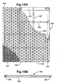
- Figures 16A and 16B show a screen assembly 900 which has a support 902 supporting a layer of coarse mesh 909 and at least one and preferably two layers of fine mesh 901 lying over the coarse mesh 901.
- the support frame 902 has sides 903, 904 and ends 905, 906.
- a plurality of optional cross members 907 and 908 extend between the sides of the frame 902. Fluid may flow transverse to either pair of sides depending on the screen assembly's orientation in a vibratory separator or shale shaker.
- the sides 903, 904 are made of channel members with a C-shaped opening.
- the C-shaped openings can receive and accommodate an upwardly projecting member or members, pin or pins, projecting upwardly from a deck or screen assembly support or channels of a vibratory separator or shale shaker.
- the sides 905, 906 to be made of such C-shaped channel members.
- the C-shaped channel opening in the screen assembly sides slides over the upwardly projecting members in the vibratory separator, or advantageously, side over the upwardly projecting members and fall over the upwardly projecting members when the screen assembly assumes the correct mounting position, whereupon the screen assembly falls over the upwardly projecting members. This ensures correct placement of the screen assembly, correct orientation and inhibits the screen assembly from moving out of correct positioning during use, thereby ensuring an excellent seal between the vibratory separator and adjacent screen assemblies.
- FIGS 17A to 17C disclose a screen assembly 920 in accordance with the present invention which has a frame 922 (like the frame 902, Figure 52A) with an optional support 929 (like the support 909, Figure 16A ) supporting screening material 921 (like the screening material 902, Figure 16A ).
- a pair of frame sides 923, 924 is spaced-apart from a pair of frame sides 925, 926.
- Frame sides 923, 924 have sections 923a, 924a, respectively which are C-shaped channel members (like the C-shaped channel members of the sides 903, 904 in cross-sectional shape) which can accommodate upwardly projecting member(s) and/or pin(s) as do the sides 803, 804 along their entire length.
- C-shaped channel sections 923a and/or 924a in a frame side or end and to locate such a C-shaped channel section or sections so that it (or they) can accommodate upwardly projecting member(s) and/or pin(s) of a deck or screen assembly mounting structure.
- FIG 18 shows a screening apparatus showing a screen assembly 400 comprising a perforate plate 401 and a screen support 402. At least one layer of screening material (not shown) overlays the perforate plate 401.
- the screen support is of any of the type disclosed with reference to Figures 16 and 17 .
- C-shape channels 405 in the screen assembly 400 allow the screen assembly to be slid into clamping rails 408, 408a arranged on each side of a basket 413 of a shale shaker 409, over upwardly projecting members, such as round or square section pins 404 spaced along the length of the clamping rails 408, 408a.
- the screen assembly 400 is slid into clamping rails 408, 408a.
- the clamping rails 408, 409 comprise a C-shape rails each having a bottom surface on which the support structure 402 of the screen assembly rests.
- Each of the C-shape rails also has a pneumatically inflatable bladder 414 fixed to an upper part 334 of the C-shape rail 330.
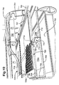
- FIG 19 shows a screening apparatus comprising a shale shaker 700 and screen assemblies 720, 721.
- the shale shaker has a basket 701 with an open bottom 702.
- the screen assemblies 720, 721 are located within rails 705, 706.
- Inflatable bladders 707, 708 are arranged on an upper leaf of the rails 705, 706, such that when inflated they push down on the screen assemblies 720,721.
- a central support 711 is mounted on a front support 709 and a similar rear support 709a beneath the screen assembly 721). Any suitable number of supports for the central support 711 may be used either at an angle to the central support of parallel with it and beneath it. Compressed air is supplied to the bladders 707, 708 via an air supply 704.
- the central support 711 has a base 712 and a top member 714.
- the top member 714 is positioned within a channel member 722 of the screen assembly 720 and also within a similar channel member (not shown) of the screen assembly 721.
- Upstanding members, such as pins 719 are arranged on the central support 711.
- a recess channel 723 in fitting 722 is slid over upstanding members 719 to inter alia provide correct location and additional vertical contact area to transmit vibration from the shale shaker to the screen asssembly.
- the screen assembly Upon inflation of the inflatable bladders 707,708, the screen assembly is deflected over the upstanding members 719, or in a different embodiment in which the upstanding members 719 are shorter than the depth of the recess channel, then deflected over the top member 714 of the central support 711.
- screened fluid flows through the screen assemblies 720, 721, through openings 710a, 710b, and then through the open bottom 702 into a typical receptacle or container.
Landscapes
- Combined Means For Separation Of Solids (AREA)
- Separation Of Solids By Using Liquids Or Pneumatic Power (AREA)
Claims (20)
- Verfahren zum Befestigen einer Siebanordnung (720, 721) an einer Siebbefestigungskonstruktion (706) einer Vibrationstrennvorrichtung (700), das das Abdichten einer Schnittstelle zwischen der Siebanordnung (720, 721) und der Siebbefestigungskonstruktion (705, 706) erleichtert, wobei die Siebbefestigungskonstruktion (706) mehrere tragende Elemente (709) umfasst, die sich von einer ersten Trennerseite der Vibrationstrennvorrichtung (700) zu einer zweiten Trennerseite der Vibrationstrennvorrichtung (700) erstrecken, wobei Material zwischen diesen Seiten in einer ersten Richtung fließen kann, die eine Richtung ist, die im Allgemeinen parallel zu diesen Seiten ist, wobei die Siebanordnung einen Träger (800) und Siebmaterial auf dem Träger aufweist, um Material, das der Vibrationstrennvorrichtung (700) zugeführt wird, zu bearbeiten, wobei der Träger vier miteinander verbundene Seiten (801, 802, 803, 804) umfasst, die zwei Seitenpaare (801, 802 und 803, 804) umfassen, ein erstes Paar (801, 802) mit einer ersten Seite (801) und einer zweiten Seite (802) und ein zweites Paar mit einer dritten Seite (803) und einer vierten Seite (804), wobei die erste Seite (801) durch einen Abstand von der zweiten Seite (802) durch die durch einen Abstand voneinander getrennte dritte und vierte Seite (803, 804) getrennt ist, wobei die erste Seite (801) und die zweite Seite (802) nach der Installation der Siebanordnung (720) in der Vibrationstrennvorrichtung (700) im Allgemeinen parallel zu der ersten Trennerseite und der zweiten Trennerseite verlaufen, wobei der Träger (800) mehrere durch Abstände voneinander getrennte Querträger (805, 806) aufweist, die sich zwischen nur einem Seitenpaar (801, 802) erstrecken und damit verbunden sind, wobei jeder Querträger (805, 806) nicht in Kontakt mit und unabhängig von allen anderen Querträgern (805, 806) ist, wobei das Verfahren den Schritt des Anordnens der Siebanordnung auf der Siebbefestigungskonstruktion (705, 706) und des Positionierens der Siebanordnung (720) in Bezug auf die Siebbefestigungskonstruktion und das Verwenden einer Vorrichtung (705, 706) mit Balligkeit umfasst, um eine ballige Konfiguration in der Siebanordnung (720, 721) herbeizuführen, dadurch gekennzeichnet ist, dass die Querträger (805, 860) alle entweder im Allgemeinen quer zu der ersten Richtung verlaufen oder alle hierzu im Allgemeinen parallel sind, wobei das Verfahren ferner den Schritt des Hinunterdrückens der ersten und zweiten Seite des Trägers (800) mit der Vorrichtung (705, 706) mit Balligkeit über einen zentralen Träger (711) umfasst, um die Balligkeit der Siebanordnung (720, 721) herbeizuführen, wobei der Träger (800) starr und dennoch ausreichend flexibel ist, so dass die Siebanordnung eine ballige Konfiguration annimmt, und die dritte Seite und die vierte Seite jeweils entlang ihrer im Wesentlichen gesamten Länge mit der Oberfläche der Siebbefestigungskonstruktion in abdichtendem Kontakt sind.
- Verfahren nach Anspruch 1, wobei die mehreren durch Abstände voneinander getrennten Querträger zwei Querträger (805, 806) sind, die im Allgemeinen parallel zu der dritten und der vierten Seite (803, 804) sind.
- Verfahren nach Anspruch 1, wobei die mehreren durch Abstände voneinander getrennten Querträger fünf Querträger sind, die im Allgemeinen parallel zu der ersten Richtung sind.
- Verfahren nach einem der Ansprüche 1 bis 3, wobei die erste Seite und die zweite Seite (801, 802) jeweils aus einem Material hergestellt sind, das weniger starr ist als das Material der dritten Seite und der vierten Seite (803, 804).
- Verfahren nach einem der Ansprüche 1 bis 4, wobei die erste Seite (801) wenigstens einen Abschnitt (803c) aufweist, der aus einem Material hergestellt ist, das weniger starr ist als das Material der dritten Seite und der vierten Seite (803, 804).
- Verfahren nach einem der Ansprüche 1 bis 5, das ferner das Verbinden eines Dichtungselements (851, 857) an einem ersten Ort einer Außenseite der ersten Seite (801) und/oder der zweiten Seite (802) umfasst, um Abhilfe gegen das ineffektive Abdichten an dem ersten Ort zu schaffen.
- Verfahren nach Anspruch 6, wobei das Dichtungselement wenigstens einen Abschnitt innerhalb einer Aussparung am ersten Ort aufweist.
- Verfahren nach einem der Ansprüche 1 bis 7, wobei die Siebbefestigungskonstruktion (407) einen Körper mit wenigstens einem nach oben hervorstehenden Element (404) aufweist, das nach oben aus dem Körperelement hervorsteht, wobei das wenigstens eine nach oben hervorstehenden Element (404) nach Größe und Konfiguration so beschaffen ist, dass es in einem entsprechenden Loch im Träger (405) aufgenommen werden kann, wobei das Verfahren ferner das Positionieren der Siebanordnung auf der Siebbefestigungskonstruktion umfasst, so dass das wenigstens eine nach oben hervorstehende Element in dem entsprechenden Loch des Trägers aufgenommen ist.
- Verfahren nach einem der Ansprüche 1 bis 8, wobei das wenigstens eine nach oben hervorstehende Element (404) mehrere durch Abstände voneinander getrennte nach oben hervorstehende Elemente sind und wobei das wenigstens eine Loch (405) im Träger mehrere durch Abstände voneinander getrennte Löcher sind, jedes zum Aufnehmen eines entsprechenden nach oben hervorstehenden Elements.
- Verfahren nach einem der Ansprüche 1 bis 9, wobei das entsprechende Loch im Träger in einem Querträger (805, 806) des Trägers vorhanden ist.
- Verfahren nach einem der Ansprüche 1 bis 10, wobei die Vibrationstrennvorrichtung (700) ein Schlammschüttelsieb zum Trennen von Komponenten von Bohrmaterial, das ihm zugeführt wird, ist, wobei das Bohrmaterial Bohrspülmittel und ausgebohrte Stücke umfasst, wobei das Schlammschüttelsieb einen Korb (701) aufweist, die Siebbefestigungskonstruktion (7) auf dem Korb ist, wobei der Träger mehrere durch Abstände voneinander getrennte Trägerlöcher durch sich hindurch aufweist, wobei jedes Loch der mehreren durch Abstände voneinander getrennten Trägerlöcher zum Aufnehmen eines Teils eines Befestigungselements dient, das verwendet wird, um die Siebanordnung mit der Siebbefestigungskonstruktion lösbar zu verbinden, wobei die Siebbefestigungskonstruktion mehrere durch Abstände voneinander getrennte Decklöcher, die den mehreren durch Abstände voneinander getrennten Trägerlöchern durch den Träger entsprechen, und Befestigungselemente, die die Siebanordnung mit der Siebbefestigungskonstruktion verbinden, aufweist, wobei jedes Befestigungselement durch das Siebmaterial, durch ein Trägerloch hindurch und in ein Deckloch eintritt, wobei das Verfahren ferner das Verbinden des Trägers mit der Siebbefestigungskonstruktion mit den Befestigungselementen umfasst.
- Verfahren nach Anspruch 11, wobei die Befestigungselemente zu einer Gruppe gehören, die aus Befestigungselementen mit Gewinde, Spornen, Bolzen, einrastenden Befestigungselementen, Fingerexpansions-Befestigungselementen, Befestigungselementen mit Luftinjektion und Befestigungselementen mit Reibungsanpassung besteht.
- Verfahren nach Anspruch 11 oder 12, wobei die Befestigungselemente adhäsiv an Ort und Stelle gesichert sind.
- Verfahren nach einem der Ansprüche 1 bis 13, wobei das Siebmaterial mehrere Lagen von Siebgeflecht umfasst.
- Verfahren nach einem der Ansprüche 1 bis 14, wobei die Siebanordnung auf dem Träger eine perforierte Platte aufweist.
- Verfahren nach einem der Ansprüche 1 bis 15, wobei die Seiten des Trägers hohle röhrenartige Elemente aufweisen.
- Verfahren nach einem der Ansprüche 1 bis 16, wobei alle Querträger im Allgemeinen quer zu der ersten Richtung verlaufen und das Material, das in die Vibrationstrennvorrichtung eingeführt wird, Feststoffe enthält, die nicht durch das Siebmaterial hindurch treten können, wobei die Feststoffe durch die Vibrationstrennvorrichtung auf einer Oberseite der Siebanordnung bewegt werden können, wobei das Verfahren ferner das gleichmäßige Bewegen der Feststoffe auf der Oberseite der Siebanordnung umfasst.
- Verfahren nach einem der Ansprüche 1 bis 17, wobei das Material Bohrmaterial ist und die Feststoffe ausgebohrte Feststoffe umfassen.
- Verfahren nach einem der Ansprüche 1 bis 18, wobei die Feststoffe auf der Oberseite der Siebanordnung ohne die Bildung von wesentlichen Totzonen auf der Oberseite der Siebanordnung bewegt werden.
- Verfahren mit einem der vorhergehenden Ansprüche, wobei die Vorrichtung mit Balligkeit aufblasbare Blasen (707, 708) und Schienen (705, 706) umfasst, wobei die aufblasbaren Blasen (707, 708) an einem oberen Flügel jeder Schiene (705, 706) angeordnet sind, wobei das Verfahren den Schritt des Aufblasens der Blase (707, 708) umfasst, um sie nach unten auf die erste und die zweite Seite (801, 802) der Siebanordnung (720) zu drücken.
Applications Claiming Priority (4)
| Application Number | Priority Date | Filing Date | Title |
|---|---|---|---|
| US10/762,768 US20050035033A1 (en) | 1999-03-25 | 2004-01-22 | Methods for sealing screen assemblies on vibratory separators |
| US10/764,348 US20050000865A1 (en) | 1998-10-30 | 2004-01-23 | Screen assemblies and vibratory separators |
| US10/867,184 US20050067327A1 (en) | 2002-01-16 | 2004-06-14 | Screen assemblies for shale shakers |
| PCT/GB2005/050008 WO2005070565A2 (en) | 2004-01-22 | 2005-01-21 | A screening apparatus and method for mounting a screen assembly in a vibratory separator |
Publications (2)
| Publication Number | Publication Date |
|---|---|
| EP1708826A2 EP1708826A2 (de) | 2006-10-11 |
| EP1708826B1 true EP1708826B1 (de) | 2012-08-15 |
Family
ID=34812104
Family Applications (1)
| Application Number | Title | Priority Date | Filing Date |
|---|---|---|---|
| EP05702153A Expired - Lifetime EP1708826B1 (de) | 2004-01-22 | 2005-01-21 | Verfahren zur Befestigung einer Siebanordnung auf einem Siebrahmen einer Vibrationstrennvorrichtung |
Country Status (4)
| Country | Link |
|---|---|
| EP (1) | EP1708826B1 (de) |
| CA (1) | CA2551620C (de) |
| NO (1) | NO20062959L (de) |
| WO (1) | WO2005070565A2 (de) |
Families Citing this family (4)
| Publication number | Priority date | Publication date | Assignee | Title |
|---|---|---|---|---|
| MX2009010195A (es) | 2007-03-26 | 2010-03-22 | Schlumberger Technology Bv | Sistema y metodo para realizar operaciones de intervencion con una herramienta submarina en forma de y. |
| US8556083B2 (en) | 2008-10-10 | 2013-10-15 | National Oilwell Varco L.P. | Shale shakers with selective series/parallel flow path conversion |
| US9643111B2 (en) | 2013-03-08 | 2017-05-09 | National Oilwell Varco, L.P. | Vector maximizing screen |
| WO2023196019A1 (en) * | 2022-04-04 | 2023-10-12 | Brett Herrington | Shaker screen retention rail and channel system |
Family Cites Families (14)
| Publication number | Priority date | Publication date | Assignee | Title |
|---|---|---|---|---|
| GB1526663A (en) | 1977-04-25 | 1978-09-27 | Derrick Mfg Corp | Vibratory screening apparatus for finely divided material |
| FR2407026A1 (fr) * | 1977-10-26 | 1979-05-25 | United Wire Group Ltd | Crible de tamisage |
| GB1578948A (en) | 1977-10-26 | 1980-11-12 | United Wire Group Ltd | Sifting screens |
| US4582597A (en) * | 1984-04-04 | 1986-04-15 | Sweco, Incorporated | Vibratory screen separator |
| GB8514983D0 (en) | 1985-06-13 | 1985-07-17 | Thule United Ltd | Screen clamping |
| GB8514982D0 (en) | 1985-06-13 | 1985-07-17 | Thule United Ltd | Screen clamping |
| US5248043A (en) * | 1992-02-28 | 1993-09-28 | Dorn Lloyd A | Modular retro-fit screen system for a screening deck |
| US5265730A (en) | 1992-04-06 | 1993-11-30 | Sweco, Incorporated | Vibratory screen separator |
| US6283302B1 (en) | 1993-08-12 | 2001-09-04 | Tuboscope I/P, Inc. | Unibody screen structure |
| US5641070A (en) | 1995-04-26 | 1997-06-24 | Environmental Procedures, Inc. | Shale shaker |
| EP0932454B1 (de) | 1996-10-15 | 2001-12-12 | Rig Technology Limited | Verbesserte vibrationssiebmaschine |
| US6439392B1 (en) * | 1997-09-02 | 2002-08-27 | Southwestern Wire Cloth, Inc. | Vibrating screen assembly with tubular frame |
| GB2394196A (en) | 2002-10-17 | 2004-04-21 | Varco Int | Screen assembly for a shale shaker |
| GB0301509D0 (en) | 2002-10-17 | 2003-02-19 | Varco Int | Vibratory seperator and screen assembly |
-
2005
- 2005-01-21 CA CA2551620A patent/CA2551620C/en not_active Expired - Fee Related
- 2005-01-21 EP EP05702153A patent/EP1708826B1/de not_active Expired - Lifetime
- 2005-01-21 WO PCT/GB2005/050008 patent/WO2005070565A2/en not_active Ceased
-
2006
- 2006-06-23 NO NO20062959A patent/NO20062959L/no not_active Application Discontinuation
Also Published As
| Publication number | Publication date |
|---|---|
| CA2551620C (en) | 2010-05-11 |
| EP1708826A2 (de) | 2006-10-11 |
| WO2005070565A3 (en) | 2005-11-24 |
| WO2005070565A2 (en) | 2005-08-04 |
| CA2551620A1 (en) | 2005-08-04 |
| NO20062959L (no) | 2006-10-12 |
Similar Documents
| Publication | Publication Date | Title |
|---|---|---|
| EP1711280B1 (de) | Vorrichtung zum trennen von feststoffen von einer feststoff enthaltenden bohrflüssigkeit und verfahren zum anbringen einer siebanordnung in einer vibrationstrennvorrichtung | |
| CA2472038C (en) | An apparatus for separating material | |
| CA2502296C (en) | Vibratory separator and screen assembly | |
| EP1472014B1 (de) | Vorrichtung zum trennen von materialien | |
| DK2056973T3 (en) | Screening arrangement for a vibration separator | |
| US6629610B1 (en) | Screen with ramps for vibratory separator system | |
| CA2531974C (en) | A method for manipulating screen assemblies and a screen assembly for a vibratory separator | |
| US20040074819A1 (en) | Screen assembly for a shale shaker | |
| US20140061140A1 (en) | Screen assembly | |
| US20050103689A1 (en) | Sealing screen assemblies and vibratory separators | |
| CA2576823C (en) | Screen assembly and shale shaker | |
| CA2551764A1 (en) | Vibratory separator and screen assembly therefor | |
| US20050035033A1 (en) | Methods for sealing screen assemblies on vibratory separators | |
| EP1708826B1 (de) | Verfahren zur Befestigung einer Siebanordnung auf einem Siebrahmen einer Vibrationstrennvorrichtung | |
| CN101010149A (zh) | 筛网组件和泥浆振动筛 | |
| CA2641636A1 (en) | Apparatus for separating material | |
| WO2009074831A2 (en) | Vibratory separator and screen assemblies therefor | |
| WO2004035235A1 (en) | A screen support | |
| MX2007001838A (es) | Ensamble de tamizado y criba vibratoria. |
Legal Events
| Date | Code | Title | Description |
|---|---|---|---|
| PUAI | Public reference made under article 153(3) epc to a published international application that has entered the european phase |
Free format text: ORIGINAL CODE: 0009012 |
|
| 17P | Request for examination filed |
Effective date: 20060614 |
|
| AK | Designated contracting states |
Kind code of ref document: A2 Designated state(s): DE FR GB IT NL |
|
| RBV | Designated contracting states (corrected) |
Designated state(s): DE FR GB IT NL |
|
| DAX | Request for extension of the european patent (deleted) | ||
| RBV | Designated contracting states (corrected) |
Designated state(s): DE FR GB IT NL |
|
| RBV | Designated contracting states (corrected) |
Designated state(s): DE FR GB IT NL |
|
| 17Q | First examination report despatched |
Effective date: 20080724 |
|
| GRAP | Despatch of communication of intention to grant a patent |
Free format text: ORIGINAL CODE: EPIDOSNIGR1 |
|
| RTI1 | Title (correction) |
Free format text: A METHOD FOR MOUNTING A SCREEN ASSEMBLY TO A SCREEN MOUNTING OF A VIBRATORY SEPARATOR |
|
| GRAS | Grant fee paid |
Free format text: ORIGINAL CODE: EPIDOSNIGR3 |
|
| GRAA | (expected) grant |
Free format text: ORIGINAL CODE: 0009210 |
|
| AK | Designated contracting states |
Kind code of ref document: B1 Designated state(s): DE FR GB IT NL |
|
| REG | Reference to a national code |
Ref country code: GB Ref legal event code: FG4D |
|
| REG | Reference to a national code |
Ref country code: DE Ref legal event code: R096 Ref document number: 602005035615 Country of ref document: DE Effective date: 20121011 |
|
| REG | Reference to a national code |
Ref country code: NL Ref legal event code: T3 |
|
| PG25 | Lapsed in a contracting state [announced via postgrant information from national office to epo] |
Ref country code: IT Free format text: LAPSE BECAUSE OF FAILURE TO SUBMIT A TRANSLATION OF THE DESCRIPTION OR TO PAY THE FEE WITHIN THE PRESCRIBED TIME-LIMIT Effective date: 20120815 |
|
| PLBE | No opposition filed within time limit |
Free format text: ORIGINAL CODE: 0009261 |
|
| STAA | Information on the status of an ep patent application or granted ep patent |
Free format text: STATUS: NO OPPOSITION FILED WITHIN TIME LIMIT |
|
| 26N | No opposition filed |
Effective date: 20130516 |
|
| REG | Reference to a national code |
Ref country code: DE Ref legal event code: R097 Ref document number: 602005035615 Country of ref document: DE Effective date: 20130516 |
|
| REG | Reference to a national code |
Ref country code: FR Ref legal event code: ST Effective date: 20130930 |
|
| PG25 | Lapsed in a contracting state [announced via postgrant information from national office to epo] |
Ref country code: DE Free format text: LAPSE BECAUSE OF NON-PAYMENT OF DUE FEES Effective date: 20130801 |
|
| REG | Reference to a national code |
Ref country code: DE Ref legal event code: R119 Ref document number: 602005035615 Country of ref document: DE Effective date: 20130801 |
|
| PG25 | Lapsed in a contracting state [announced via postgrant information from national office to epo] |
Ref country code: FR Free format text: LAPSE BECAUSE OF NON-PAYMENT OF DUE FEES Effective date: 20130131 |
|
| PGFP | Annual fee paid to national office [announced via postgrant information from national office to epo] |
Ref country code: NL Payment date: 20210113 Year of fee payment: 17 |
|
| REG | Reference to a national code |
Ref country code: NL Ref legal event code: MM Effective date: 20220201 |
|
| PG25 | Lapsed in a contracting state [announced via postgrant information from national office to epo] |
Ref country code: NL Free format text: LAPSE BECAUSE OF NON-PAYMENT OF DUE FEES Effective date: 20220201 |
|
| PGFP | Annual fee paid to national office [announced via postgrant information from national office to epo] |
Ref country code: GB Payment date: 20231130 Year of fee payment: 20 |
|
| REG | Reference to a national code |
Ref country code: GB Ref legal event code: PE20 Expiry date: 20250120 |
|
| PG25 | Lapsed in a contracting state [announced via postgrant information from national office to epo] |
Ref country code: GB Free format text: LAPSE BECAUSE OF EXPIRATION OF PROTECTION Effective date: 20250120 |