EP1708914B1 - Procede empechant un vehicule sur voie de passer sur un obstacle, et vehicule sur voie - Google Patents
Procede empechant un vehicule sur voie de passer sur un obstacle, et vehicule sur voie Download PDFInfo
- Publication number
- EP1708914B1 EP1708914B1 EP05701107A EP05701107A EP1708914B1 EP 1708914 B1 EP1708914 B1 EP 1708914B1 EP 05701107 A EP05701107 A EP 05701107A EP 05701107 A EP05701107 A EP 05701107A EP 1708914 B1 EP1708914 B1 EP 1708914B1
- Authority
- EP
- European Patent Office
- Prior art keywords
- vehicle
- distance
- track
- emergency
- braking
- Prior art date
- Legal status (The legal status is an assumption and is not a legal conclusion. Google has not performed a legal analysis and makes no representation as to the accuracy of the status listed.)
- Expired - Lifetime
Links
- 238000000034 method Methods 0.000 title claims description 30
- 230000000977 initiatory effect Effects 0.000 claims description 2
- 230000001133 acceleration Effects 0.000 description 3
- 238000010586 diagram Methods 0.000 description 2
- 230000005484 gravity Effects 0.000 description 2
- 238000005381 potential energy Methods 0.000 description 2
- 230000001960 triggered effect Effects 0.000 description 2
- 230000000007 visual effect Effects 0.000 description 2
- 238000005299 abrasion Methods 0.000 description 1
- 150000001875 compounds Chemical class 0.000 description 1
- 230000008878 coupling Effects 0.000 description 1
- 238000010168 coupling process Methods 0.000 description 1
- 238000005859 coupling reaction Methods 0.000 description 1
- 230000000881 depressing effect Effects 0.000 description 1
- 238000001514 detection method Methods 0.000 description 1
- 238000007688 edging Methods 0.000 description 1
- 238000005265 energy consumption Methods 0.000 description 1
- 239000002360 explosive Substances 0.000 description 1
- 239000012530 fluid Substances 0.000 description 1
- 238000005259 measurement Methods 0.000 description 1
- 230000007246 mechanism Effects 0.000 description 1
- 239000007787 solid Substances 0.000 description 1
- 239000000725 suspension Substances 0.000 description 1
Images

Classifications
-
- B—PERFORMING OPERATIONS; TRANSPORTING
- B61—RAILWAYS
- B61L—GUIDING RAILWAY TRAFFIC; ENSURING THE SAFETY OF RAILWAY TRAFFIC
- B61L23/00—Control, warning or like safety means along the route or between vehicles or trains
- B61L23/04—Control, warning or like safety means along the route or between vehicles or trains for monitoring the mechanical state of the route
- B61L23/041—Obstacle detection
-
- B—PERFORMING OPERATIONS; TRANSPORTING
- B61—RAILWAYS
- B61D—BODY DETAILS OR KINDS OF RAILWAY VEHICLES
- B61D15/00—Other railway vehicles, e.g. scaffold cars; Adaptations of vehicles for use on railways
- B61D15/06—Buffer cars; Arrangements or construction of railway vehicles for protecting them in case of collisions
-
- B—PERFORMING OPERATIONS; TRANSPORTING
- B61—RAILWAYS
- B61F—RAIL VEHICLE SUSPENSIONS, e.g. UNDERFRAMES, BOGIES OR ARRANGEMENTS OF WHEEL AXLES; RAIL VEHICLES FOR USE ON TRACKS OF DIFFERENT WIDTH; PREVENTING DERAILING OF RAIL VEHICLES; WHEEL GUARDS, OBSTRUCTION REMOVERS OR THE LIKE FOR RAIL VEHICLES
- B61F19/00—Wheel guards; Bumpers; Obstruction removers or the like
- B61F19/06—Nets, catchers, or the like for catching obstacles or removing them from the track
- B61F19/08—Nets, catchers, or the like for catching obstacles or removing them from the track of the drop-down type
-
- Y—GENERAL TAGGING OF NEW TECHNOLOGICAL DEVELOPMENTS; GENERAL TAGGING OF CROSS-SECTIONAL TECHNOLOGIES SPANNING OVER SEVERAL SECTIONS OF THE IPC; TECHNICAL SUBJECTS COVERED BY FORMER USPC CROSS-REFERENCE ART COLLECTIONS [XRACs] AND DIGESTS
- Y02—TECHNOLOGIES OR APPLICATIONS FOR MITIGATION OR ADAPTATION AGAINST CLIMATE CHANGE
- Y02T—CLIMATE CHANGE MITIGATION TECHNOLOGIES RELATED TO TRANSPORTATION
- Y02T30/00—Transportation of goods or passengers via railways, e.g. energy recovery or reducing air resistance
Definitions
- the invention concerns a track-bound vehicle, such as for instance a light rail train, a tram, a trolley-bus, or a hybrid vehicle such as a tram-on-tires, shaped so that a gap exists between the track or, as the case may be, level road surface or more generally the ground and the lower front edge of the vehicle, comprising a device to close this gap.
- a track-bound vehicle such as for instance a light rail train, a tram, a trolley-bus, or a hybrid vehicle such as a tram-on-tires, shaped so that a gap exists between the track or, as the case may be, level road surface or more generally the ground and the lower front edge of the vehicle, comprising a device to close this gap.
- the invention also concerns the corresponding method.
- the gap defined above carries the risk that persons or objects in front of the vehicle may be caught underneath the vehicle.
- DE20002278U it has been suggested in DE20002278U to provide the front end of the vehicle with a height-adjustable nose apron covering the gap.
- This apron is connected to the vehicle by at least one adjustment unit formed as an electro-mechanical positioning drive.
- the drive is automatically controlled by a controller to constantly adjust the position of the apron based on the actual vertical distance between the vehicle body and the rail level, measured by a sensor unit. Thanks to this permanent adjustment, the troughs and bumps on the track are compensated for.
- the resulting device however appears to be very complicated and expensive.
- the energy consumption of the drive unit is not insignificant and its service life will not be long, since it is continuously in service.
- US 2001/0035657 discloses an other vehicle provide with an inflatable element which is deployed when the risk of a collision is detected.
- a method according to claim 1 for preventing a track-bound vehicle shaped so as to form a gap between the vehicle and the ground from overrunning an obstacle.
- track-bound vehicle as used herein is a reference to vehicles required to run on tracks, such as trains and trams, as well as vehicles able to run on both tracks and general road surfaces.
- the shield When actuated, the shield is placed between the lower front edge of the vehicle and the track or ground level and fixed in this position.
- the shield acts as a kind of rake blade, edging along possible obstacles in front of the vehicle or pushing them aside. Since actuation is required only at the time of emergency, the shield does not have to be provided with a complex control system. In normal operation, the gap is not covered.
- the shield can be held in a recessed position and be hidden, e.g. behind the front spoiler or under the vehicle.
- the emergency condition is met if the difference between the distance between the obstacle and the vehicle on the one hand and the braking distance of the vehicle on the other hand is smaller than a predetermined value.
- the predetermined value can be a constant value or a value which depends e.g. on the vehicle speed or on the braking distance of the vehicle.
- the method comprises a step of detecting actuation of a driver's control member. This detection is used as one of the parameters on which the determination of the emergency condition is based. Different tests can be defined, e.g.:
- a sensor (such as a camera, a radar device or a microwave telemeter) can be used to detect any obstacles on the track.
- the extension of the shield can be triggered by other events that are likely to be representative of a situation in which the vehicle could overrun an obstacle. Actuation may first of all be carried out by the driver. For instance, a pushbutton on a driver's control panel can be used to initiate the extension.
- the method further comprises a step of generating an emergency output signal on a driver's control board of the vehicle when the distance between the obstacle and the vehicle is smaller than the braking distance of the vehicle.
- the extension of the shield can be triggered by mechanical or hydraulic means.
- the signals are electric, analogue or digital signals.
- the step of detecting an emergency situation comprises a step of generating an electric signal representing the occurrence of a detected emergency situation.
- the step of extending the shield comprises a step of automatically initiating extension of the shield based on said electric signal.
- the shield Due to varying ground clearance, positioning of the shield is designed to allow coverage of every possible height of the gap, whereby the lower edge of the shield may reach ground level. In order to ensure the smallest possible clearance of the lower edge of the actuated shield from the ground, the shield may be pushed against the ground by applying additional force such as an elastic force.
- the lower edge of the shield can be provided with spring-loaded skids, reels, wheels or similar components to roll or slide on the ground.
- the lower edge of the shield may be executed as a replaceable abrasion edge. Alternatively, a small, predetermined clearance can be maintained between the shield and the ground.
- Positioning the shield can be effected using a sliding, rotating or tipping motion.
- the actuated shield may be lowered using gravitational acceleration, or accelerated by applying additional power.
- the additional power can be provided by a motor such as an electromechanical actuator or by releasing energy previously stored in an energy accumulator.
- the method further comprises a step of maintaining the shield in the retracted position as long as no emergency situation is detected.
- the step of extending the shield comprises a step of releasing a lock that maintains the shield in the retracted position.
- the lock can cooperate directly with the shield, or indirectly with the actuating means providing additional power.
- the procedure further comprises a step of automatically decelerating the vehicle when actuation of the driver's control member has been detected.
- a track-bound vehicle according to claim 9, shaped so as to form a gap between the vehicle and the ground.
- the shield may be in one or in several parts, for instance providing grooves for coupling devices.
- the shield may be executed as a solid panel, a grate-like frame or an assembly of bars.
- part of the vehicle front itself for instance the spoiler
- the shield can also consist of one or more inflatable cushions.
- the signals generated can be analogue or digital electric signals.
- the manually operated control member is connected to a braking system of the vehicle and initiates an emergency braking command.
- the distance sensor can be any suitable proximity sensor, a camera, a radar device, a microwave telemeter, etc.
- the sensor can be fixedly mounted to the front or the roof of the vehicle.
- a drive system can be provided for moving the distance sensor in such a way that the distance sensor follows the track.
- the position of the distance sensor can be controlled so as to compensate for the movements of the car body and the curves of the track.
- the relative movement between the vehicle body and the running gear can be used as an input variable for pivoting the sensor. If a camera is used in connection with image recognition processing, the curve of the track can be directly recognised by the image processor and a signal can be generated to allow the camera to follow its target, i.e. the track or road.
- the braking distance is preferably assessed based on the speed of the vehicle, measured by a vehicle speed sensor.
- the inertia of the vehicle can also be assessed, so that the assessed braking distance is longer when, for a given vehicle speed, the assessed inertia of the vehicle is greater.
- Various means can be used to assess the inertia of the vehicle. For instance, force or distance measurements can be carried out on the secondary suspension of the vehicle. Alternatively, the history of acceleration and deceleration of the vehicle can be used.
- the means for extending the shield comprise lock means for maintaining the shield in the retracted position and for releasing the shield in response to the emergency signal.
- the shield is secured in the retracted position to avoid any unwanted extension.
- the locking means will also be used to reset the shield in the retracted position after it has been extended.
- the shield can be extended by gravity. However, to ensure quicker and more reliable operation, it may be preferable to provide the means for extending the shield with drive means for moving the shield from the retracted position towards the extended position.
- the drive means may comprise a motor such as an electromechanical actuator.
- a system comprising an energy accumulator which stores potential energy in a loaded state and releases kinetic energy when unloading to move the shield from the retracted position towards the extended position is preferred, since an energy accumulator seems to be the most efficient way of providing a non-repeated motion requiring quick acceleration, i.e. power.
- the energy accumulator can be of any suitable type. Energy can be stored as a pressurized fluid or an explosive chemical compound. This may be particularly relevant if the shield comprises an inflatable cushion.
- the energy accumulator applies to the shield in the extended position a force opposed to the retraction of the shield.
- the shield is provided with a follower cooperating with the ground in the extended position.
- Spring-loaded skids, reels, wheels or similar components, located at the lower edge of the shield so as to roll or slide on the ground can be used as followers.
- the follower may be adapted to cooperate with different parts of the ground, e.g. the rail, or the track itself.
- the drive means are such that the energy accumulator is reloaded by the reset movement of the shield from the extended position back to the retracted position.
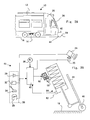
- a track-bound vehicle 10 such as a light rail vehicle, a tram, a trolley bus or a hybrid vehicle such as a tram-on-tires is provided with a car body 12 supported on a running gear 14, which follows a track on the ground 16.
- the track can be a railroad or a track defined by visual or electromagnetic guiding landmarks or markers.
- the front part 20 of the car body forms a driver's cab.
- a gap 22 is provided between the lower edge of the driver's cab and the ground. This gap 22 is necessary for travelling on an uneven track because of the overhanging position of the front part 20 of the vehicle in relation to the running gear 14.
- the dimension of the gap can be of a maximum height of between 220 mm and 280 mm while the vehicle runs on a level or flat track, or between 60 mm and 350 mm approximately when the vehicle is driven through troughs and over bumps in the track system.
- a camera 24 is mounted on a drive unit 25 fixed to the front end of the vehicle, under the windscreen 26 of the driver's cab 20.
- the camera field 28 is directed towards the track ahead of the vehicle.
- an obstacle 29 has been represented in front of the vehicle, ahead of the field 28.
- the drive unit 25 allows the camera to pivot so as to follow the track through curves.
- control panel 30 of the driver's cab is also provided with a series of control members, including for example a brake pedal 32, a control lever 34 and an emergency pushbutton 36.
- the vehicle is also provided with a vehicle speed sensor 38.
- These instruments are electrically connected to an electronic control unit 40 to form a signal generator 41.
- the control unit is also connected to a visual and/or audio indicator 39 on the control panel 30.
- the control unit 30 is also connected to the drive unit 25 so as to control the position of the camera 24.
- the control unit comprises a sub-unit for processing the images of the camera in real time so that the curves of the track in front of the vehicle can be recognised.
- the control unit 30 uses this information to control the drive unit 25 so that the camera follows the track and compensates for the movements of the front end of the vehicle with respect to the track.
- the lower edge of the front end of the vehicle body is provided with a recess 42 shown in figure 1A , for receiving a shield 44.
- the shield 44 is movable between a fully retracted position and an extended position.
- the shield 44 is provided with rollers 46 at its lower edge and powered by an energy accumulator 50, comprising a cylinder 52, a piston 54 guided in the cylinder 52 and a loaded spring 56.
- the piston 54 is locked by a latch 58, which is controlled by an electromechanical actuator 60 connected to the control unit 40.
- a position sensor 62 detects the position of the shield 44.
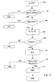
- the routine starts at step 100.
- decision block 102 the control unit 40 determines whether the vehicle speed, measured by the speed sensor 38, is higher than zero and determines from the signal of sensor 62 whether the shield is in the retracted position. If this is case, the routine proceeds to step 104 where the camera 24 detects the presence of obstacles. If an obstacle is detected, the routine proceeds to step 106 where the distance D to the obstacle is assessed using image recognition. The braking distance D B of the vehicle for the measured vehicle speed V is calculated and compared to the distance to the obstacle. Then the routine proceeds to step 108 to compare the braking distance D B to the distance D.
- step 110 the routine proceeds to step 110, where an alarm signal ALS is sent by the control unit 40 to the driver via the indicator 39. Then the routine proceeds to step 112 to determine the state of the actuators 32 and 34. If the driver has actuated one of the actuators 32 or 34, the routine proceeds to step 114 and the control unit 40 sends an emergency signal EMS to the electromechanical actuator 60, which pivots the latch 58 so as to unlock the piston 54, as shown in figure 2B .
- the piston 54 is pushed by the spring 56 and moves the shield 44 towards the extended position, until the rollers 46 abut on the ground 16. In the extended position, the spring 56 is not completely unloaded and applies pressure on the piston 54 to prevent retraction of the shield.
- the control unit 40 can also detect other events such as depressing a special pushbutton 36, which allows the driver to extend the shield without the necessity of other signals being present.
- the shield can be retracted manually by the driver or via driving means.
- the routine is repeated continuously (e.g. every second) as part of the control procedures of the vehicle.
- This procedure ensures that the shield is extended only when actuation of a driver's control member has been detected and the distance between the obstacle and the vehicle is smaller than the braking distance of the vehicle. This avoids unnecessary actuations of the shield and gives the driver useful assistance in emergency situations.
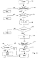
- the procedure of figure 4 differs from the procedure of figure 3 merely in that it comprises a step of automatically decelerating the vehicle (10) when said emergency condition is met. More specifically, if at step 112 the driver has not actuated one of the actuators 32 or 34, the routine proceeds to step 116 to compare the difference D-D B to a second predetermined value P 2 which is less than P 1 . If this is the case, then an emergency braking signal EBS is emitted to directly control the braking system of the vehicle and the emergency signal EMS is simultaneously sent to the electromechanical actuator 60 to extend the shield.
- P 1 can be a fixed value, superior or equal to zero or a value determined based on external parameters such as the vehicle speed.
- P 2 can be a fixed value, above, equal to or below zero, or a value determined based on external parameters such as the vehicle speed.
- this additional step requires that the presence sensor 24 for detecting the presence of an obstacle be very reliable, so that no undesired emergency braking occurs. Otherwise, it is preferable to use the method of figure 3 , which ensures that the driver keeps full control of the vehicle braking.
- the control lever 34 can be mechanically connected to the latch 58.
- the energy accumulator 50 has been described in a very schematic way. Appropriate mechanisms for storing the potential energy and releasing it can be found for instance in the field of power circuit breakers. Several latches can be used in series to limit the power of the electromechanical actuator 60. It is also possible to use gravity to extend the shield.
- An electric motor or a pneumatic or hydraulic cylinder can be used instead of the energy accumulator.
- Other types of energy accumulators are also possible.
- Drive means can be provided to raise the shield back to the retracted position.
- the camera 24 can be mounted at any suitable location allowing the camera field 28 to cover the track ahead of the vehicle.
- the camera can be fixed so that the drive unit 25 is optional.
- the shield instead of extending the shield down to the ground level, it is also possible to extend the shield to an extended position above ground level, whereby the extended position is controlled as a function of a distance measured between a part of the vehicle and the ground and/or a distance measured between the shield and the ground.
- the procedure of figure 3 is only one example of a method for controlling the shield. Alternative procedures can be carried out.
- the steps of the procedure can be permuted.
- the routine can start with step 112.
- steps of the procedure can also be processed in parallel, for instance all steps where the input signals are processed.
- the driver can choose between a first mode of operation including steps 116 to 118 and a second mode of operation excluding steps 116 to 118. According to yet another embodiment, only step 116 is omitted. According to yet another embodiment, the emergency signal EMS is generated before the routine proceeds to step 112.
Landscapes
- Engineering & Computer Science (AREA)
- Mechanical Engineering (AREA)
- Transportation (AREA)
- Regulating Braking Force (AREA)
- Electric Propulsion And Braking For Vehicles (AREA)
- Train Traffic Observation, Control, And Security (AREA)
- Package Frames And Binding Bands (AREA)
- Basic Packing Technique (AREA)
- Radar Systems Or Details Thereof (AREA)
- Automatic Cycles, And Cycles In General (AREA)
Claims (13)
- Procédé destiné à empêcher un véhicule sur voie (10) ayant une forme permettant de former un espace (22) entre le véhicule (10) et le sol (16) de rouler sur un obstacle comprenant les étapes consistant à :- détecter un obstacle sur la voie devant le véhicule (10),- déterminer la distance entre le véhicule (10) et l'obstacle ;- déterminer la distance de freinage du véhicule (10) ;- déterminer une situation d'urgence en se fondant sur les paramètres comprenant au moins la distance entre le véhicule et l'obstacle et la distance de freinage du véhicule ;caractérisé en ce qu'il comprend également l'étape consistant à :- générer un signal d'urgence lorsque la situation d'urgence se produit ;- générer une instruction de freinage d'urgence lorsqu'un élément de commande du conducteur (34) raccordé à un système de freinage du véhicule est actionné ;- déployer un bouclier (44) depuis une position rétractée vers une position déployée pour au moins partiellement fermer l'espace (22) en réponse au dit signal d'urgence et à ladite instruction de freinage d'urgence.
- Procédé selon la revendication 1, dans lequel la situation d'urgence se produit si la différence entre la distance entre l'obstacle et le véhicule (10) d'une part, et la distance de freinage du véhicule d'autre part, est inférieure à une valeur prédéterminée.
- Procédé selon la revendication 1 ou la revendication 2, dans lequel la situation d'urgence se produit si et seulement si l'actionnement de l'élément de commande du conducteur a été détecté, alors que la différence entre la distance entre l'obstacle et le véhicule (10) d'une part, et la distance de freinage du véhicule d'autre part, est inférieure à une valeur prédéterminée.
- Procédé selon l'une quelconque des revendications précédentes, comprenant en outre une étape consistant à générer un signal d'alarme sur le tableau de bord de commande du conducteur du véhicule lorsque la différence entre la distance entre l'obstacle et le véhicule (10) d'une part, et la distance de freinage du véhicule d'autre part, est inférieure à une valeur prédéterminée.
- Procédé selon l'une quelconque des revendications précédentes, dans lequel l'étape consistant à déterminer la distance de freinage du véhicule comprend la mesure de la vitesse du véhicule.
- Procédé selon l'une quelconque des revendications précédentes, dans lequel l'étape consistant à déterminer la distance de freinage du véhicule comprend la détermination de la masse du véhicule.
- Procédé selon l'une quelconque des revendications précédentes, comprenant en outre une étape consistant à ralentir automatiquement le véhicule (10) lorsque l'actionnement de l'élément de commande du conducteur a été détecté.
- Procédé selon l'une quelconque des revendications précédentes, comprenant en outre une étape consistant à ralentir automatiquement le véhicule (10) lorsque ladite situation d'urgence se produit.
- Véhicule sur voie (10) ayant une forme telle qu'un espace (22) est formé entre le véhicule et le sol et comprenant :- un bouclier (44) qui peut se déplacer d'une position repliée vers une position déployée jusqu'à fermer au moins partiellement l'espace (22) ;- des moyens permettant de déployer le bouclier d'une position rétractée vers la position déployée en réponse à un signal d'urgence ; et- un moyen de génération d'un signal d'urgence permettant de générer le signal d'urgence lorsqu'une situation d'urgence se produit,caractérisé en ce qu'il comprend en outre :- un détecteur de distance permettant de générer un signal de distance représentatif de la distance entre le véhicule (10) et un obstacle sur une voie devant le véhicule ;- un moyen de détermination de la distance de freinage permettant de générer un signal de distance de freinage, ladite situation d'urgence étant déterminée en se fondant sur au moins le signal de distance et le signal de distance de freinage ;- un élément de commande du conducteur raccordé à un système de freinage du véhicule, initiant une instruction de freinage d'urgence,dans lequel la situation d'urgence est déterminée en se fondant sur au moins le signal de distance, le signal de distance de freinage et l'instruction de freinage d'urgence.
- Véhicule sur voie selon la revendication 9, dans lequel la situation d'urgence se produit si une instruction de freinage d'urgence a été initiée alors que la différence entre la distance entre l'obstacle et le véhicule (10) d'une part, et la distance de freinage du véhicule d'autre part, est inférieure à une valeur prédéterminée.
- Véhicule sur voie selon la revendication 9, dans lequel la situation d'urgence se produit si et seulement si une instruction de freinage d'urgence a été initiée, alors que la différence entre la distance entre l'obstacle et le véhicule (10) d'une part, et la distance de freinage du véhicule d'autre part, est inférieure à une valeur prédéterminée.
- Véhicule sur voie selon l'une quelconque des revendications 9 à 11, comprenant en outre un système d'entraînement permettant de déplacer le détecteur de distance (24) de telle manière que le détecteur de distance suive la voie.
- Véhicule sur voie selon l'une quelconque des revendications 9 à 13, dans lequel le moyen permettant de déployer le bouclier comprend un système d'entraînement (50) permettant de déplacer le bouclier de la position rétractée vers la position déployée.
Applications Claiming Priority (2)
| Application Number | Priority Date | Filing Date | Title |
|---|---|---|---|
| GBGB0401612.7A GB0401612D0 (en) | 2004-01-26 | 2004-01-26 | Method for preventing a track-bound vehicle from overrunning an obstacle and track-bound vehicle |
| PCT/EP2005/000591 WO2005070742A1 (fr) | 2004-01-26 | 2005-01-21 | Procede empechant un vehicule sur voie de passer sur un obstacle, et vehicule sur voie |
Publications (2)
| Publication Number | Publication Date |
|---|---|
| EP1708914A1 EP1708914A1 (fr) | 2006-10-11 |
| EP1708914B1 true EP1708914B1 (fr) | 2010-01-06 |
Family
ID=31971433
Family Applications (1)
| Application Number | Title | Priority Date | Filing Date |
|---|---|---|---|
| EP05701107A Expired - Lifetime EP1708914B1 (fr) | 2004-01-26 | 2005-01-21 | Procede empechant un vehicule sur voie de passer sur un obstacle, et vehicule sur voie |
Country Status (5)
| Country | Link |
|---|---|
| EP (1) | EP1708914B1 (fr) |
| AT (1) | ATE454301T1 (fr) |
| DE (1) | DE602005018741D1 (fr) |
| GB (1) | GB0401612D0 (fr) |
| WO (1) | WO2005070742A1 (fr) |
Families Citing this family (9)
| Publication number | Priority date | Publication date | Assignee | Title |
|---|---|---|---|---|
| DE102007016711A1 (de) | 2007-04-04 | 2008-10-09 | Bombardier Transportation Gmbh | Erkennung von die Sicherheit der Passagiere beeinträchtigenden Zuständen bei einem Schienenfahrzeug |
| KR101014262B1 (ko) | 2008-12-11 | 2011-02-16 | 한국철도기술연구원 | 철도차량의 배장 장치 |
| DE102013225674C5 (de) | 2013-12-11 | 2018-12-13 | Bombardier Transportation Gmbh | Verfahren zur Darstellung von Informationen für Verkehrsteilnehmer über den Betrieb eines Schienenfahrzeugs |
| FR3025469B1 (fr) | 2014-09-10 | 2018-02-16 | Alstom Transp Tech | Dispositif de protection des pietons en cas de choc avec un vehicule |
| CN104960490A (zh) * | 2015-06-24 | 2015-10-07 | 广西大学 | 车底阻挡装置 |
| CN104943652A (zh) * | 2015-06-24 | 2015-09-30 | 广西大学 | 车外行人防护装置 |
| DE102016221513B3 (de) * | 2016-11-03 | 2018-01-11 | Bombardier Transportation Gmbh | Schienenfahrzeug mit Schienenräumer und Schienenräumer für ein Schienenfahrzeug |
| DE102016221512B3 (de) * | 2016-11-03 | 2018-01-11 | Bombardier Transportation Gmbh | Schienenfahrzeug mit einer Schutzeinrichtung und Schutzeinrichtung für ein Schienenfahrzeug |
| DE102019214990A1 (de) * | 2019-09-30 | 2021-04-01 | Siemens Mobility GmbH | Fahrzeug mit Frontverkleidung |
Family Cites Families (5)
| Publication number | Priority date | Publication date | Assignee | Title |
|---|---|---|---|---|
| DE124940C (fr) * | 1901-01-21 | |||
| DE4218484A1 (de) * | 1991-06-05 | 1992-12-10 | Akebono Brake Ind | Automatisches bremsensteuerungssystem |
| JP3467339B2 (ja) * | 1994-12-20 | 2003-11-17 | タカタ株式会社 | 車両の衝突状態制御システム |
| DE20002278U1 (de) * | 2000-02-09 | 2001-06-21 | Siemens Duewag Schienenfahrzeuge GmbH, 47829 Krefeld | Schienenfahrzeug, insbesondere Straßen- oder Stadtbahnwagen für den Nahverkehr |
| FR2806997B1 (fr) * | 2000-04-04 | 2006-06-02 | Alstom | Dispositif de protection d'un vehicule contre le choc |
-
2004
- 2004-01-26 GB GBGB0401612.7A patent/GB0401612D0/en not_active Ceased
-
2005
- 2005-01-21 AT AT05701107T patent/ATE454301T1/de active
- 2005-01-21 WO PCT/EP2005/000591 patent/WO2005070742A1/fr not_active Ceased
- 2005-01-21 EP EP05701107A patent/EP1708914B1/fr not_active Expired - Lifetime
- 2005-01-21 DE DE602005018741T patent/DE602005018741D1/de not_active Expired - Lifetime
Also Published As
| Publication number | Publication date |
|---|---|
| ATE454301T1 (de) | 2010-01-15 |
| DE602005018741D1 (de) | 2010-02-25 |
| GB0401612D0 (en) | 2004-02-25 |
| WO2005070742A1 (fr) | 2005-08-04 |
| EP1708914A1 (fr) | 2006-10-11 |
Similar Documents
| Publication | Publication Date | Title |
|---|---|---|
| CN106427725B (zh) | 电动滑动平台组件 | |
| US3986577A (en) | Device for detecting obstructions in path of a vehicle | |
| CN100441457C (zh) | 滑动踏板 | |
| CN101801746B (zh) | 用于汽车的驾驶员辅助系统 | |
| US11958512B2 (en) | Monitoring and communication device of a vehicle | |
| US8297639B2 (en) | Method and control system for a fifth wheel coupling sliding device having a distance measurement for detecting obstructions | |
| US20120053797A1 (en) | Method and control system for a fifth wheel coupling sliding device having detection of the bent position of towing vehicles and trailers | |
| US7971918B2 (en) | Extendable sleeper and method of operation | |
| US6726260B1 (en) | Extending bumper with combined stiffener and method | |
| JP2011060113A (ja) | 車両の衝突回避支援装置 | |
| CN110723099B (zh) | 车身构造 | |
| WO2005070742A1 (fr) | Procede empechant un vehicule sur voie de passer sur un obstacle, et vehicule sur voie | |
| CN110198865B (zh) | 用于设置在轨道车辆的车厢的壁的门开口中的门模块 | |
| JP7773843B2 (ja) | 作業車両 | |
| US20220412097A1 (en) | Ascending mechanised access ramp (a-mar) | |
| WO2013090920A1 (fr) | Trappe de plateforme à niveau élevé avec glissière mobile intégrée pour franchissement d'écart de plateforme ferroviaire | |
| WO2020108854A1 (fr) | Agencement de porte, système de porte et véhicule | |
| KR20120103188A (ko) | 비상제동을 위한 무인 전동차용 충격력 감지장치 | |
| JP4213661B2 (ja) | 自動運転車両の逸脱防止システム | |
| US20190168729A1 (en) | Railway vehicle comprising an emergency braking device | |
| JP2005247046A (ja) | ブレーキ制御システム | |
| JP2008029143A (ja) | 列車運転システム及び地上側運転装置 | |
| KR20220132924A (ko) | 차량의 적재물 이탈 방지 장치 | |
| KR100599291B1 (ko) | 차량의 브레이크페달 이탈방지 장치 | |
| CN216139984U (zh) | 一种交通设备及其电动伸缩踏板装置 |
Legal Events
| Date | Code | Title | Description |
|---|---|---|---|
| PUAI | Public reference made under article 153(3) epc to a published international application that has entered the european phase |
Free format text: ORIGINAL CODE: 0009012 |
|
| 17P | Request for examination filed |
Effective date: 20060719 |
|
| AK | Designated contracting states |
Kind code of ref document: A1 Designated state(s): AT BE BG CH CY CZ DE DK EE ES FI FR GB GR HU IE IS IT LI LT LU MC NL PL PT RO SE SI SK TR |
|
| DAX | Request for extension of the european patent (deleted) | ||
| 17Q | First examination report despatched |
Effective date: 20071120 |
|
| GRAP | Despatch of communication of intention to grant a patent |
Free format text: ORIGINAL CODE: EPIDOSNIGR1 |
|
| GRAS | Grant fee paid |
Free format text: ORIGINAL CODE: EPIDOSNIGR3 |
|
| GRAA | (expected) grant |
Free format text: ORIGINAL CODE: 0009210 |
|
| RAP1 | Party data changed (applicant data changed or rights of an application transferred) |
Owner name: BOMBARDIER TRANSPORTATION GMBH |
|
| AK | Designated contracting states |
Kind code of ref document: B1 Designated state(s): AT BE BG CH CY CZ DE DK EE ES FI FR GB GR HU IE IS IT LI LT LU MC NL PL PT RO SE SI SK TR |
|
| REG | Reference to a national code |
Ref country code: GB Ref legal event code: FG4D |
|
| REG | Reference to a national code |
Ref country code: CH Ref legal event code: EP |
|
| REG | Reference to a national code |
Ref country code: IE Ref legal event code: FG4D |
|
| REF | Corresponds to: |
Ref document number: 602005018741 Country of ref document: DE Date of ref document: 20100225 Kind code of ref document: P |
|
| REG | Reference to a national code |
Ref country code: CH Ref legal event code: NV Representative=s name: ABREMA AGENCE BREVET ET MARQUES, GANGUILLET |
|
| REG | Reference to a national code |
Ref country code: NL Ref legal event code: VDEP Effective date: 20100106 |
|
| PG25 | Lapsed in a contracting state [announced via postgrant information from national office to epo] |
Ref country code: SI Free format text: LAPSE BECAUSE OF FAILURE TO SUBMIT A TRANSLATION OF THE DESCRIPTION OR TO PAY THE FEE WITHIN THE PRESCRIBED TIME-LIMIT Effective date: 20100106 |
|
| LTIE | Lt: invalidation of european patent or patent extension |
Effective date: 20100106 |
|
| PG25 | Lapsed in a contracting state [announced via postgrant information from national office to epo] |
Ref country code: ES Free format text: LAPSE BECAUSE OF FAILURE TO SUBMIT A TRANSLATION OF THE DESCRIPTION OR TO PAY THE FEE WITHIN THE PRESCRIBED TIME-LIMIT Effective date: 20100417 Ref country code: PT Free format text: LAPSE BECAUSE OF FAILURE TO SUBMIT A TRANSLATION OF THE DESCRIPTION OR TO PAY THE FEE WITHIN THE PRESCRIBED TIME-LIMIT Effective date: 20100506 Ref country code: LT Free format text: LAPSE BECAUSE OF FAILURE TO SUBMIT A TRANSLATION OF THE DESCRIPTION OR TO PAY THE FEE WITHIN THE PRESCRIBED TIME-LIMIT Effective date: 20100106 Ref country code: IS Free format text: LAPSE BECAUSE OF FAILURE TO SUBMIT A TRANSLATION OF THE DESCRIPTION OR TO PAY THE FEE WITHIN THE PRESCRIBED TIME-LIMIT Effective date: 20100506 Ref country code: NL Free format text: LAPSE BECAUSE OF FAILURE TO SUBMIT A TRANSLATION OF THE DESCRIPTION OR TO PAY THE FEE WITHIN THE PRESCRIBED TIME-LIMIT Effective date: 20100106 |
|
| PG25 | Lapsed in a contracting state [announced via postgrant information from national office to epo] |
Ref country code: PL Free format text: LAPSE BECAUSE OF FAILURE TO SUBMIT A TRANSLATION OF THE DESCRIPTION OR TO PAY THE FEE WITHIN THE PRESCRIBED TIME-LIMIT Effective date: 20100106 Ref country code: FI Free format text: LAPSE BECAUSE OF FAILURE TO SUBMIT A TRANSLATION OF THE DESCRIPTION OR TO PAY THE FEE WITHIN THE PRESCRIBED TIME-LIMIT Effective date: 20100106 Ref country code: MC Free format text: LAPSE BECAUSE OF NON-PAYMENT OF DUE FEES Effective date: 20100131 |
|
| PG25 | Lapsed in a contracting state [announced via postgrant information from national office to epo] |
Ref country code: CY Free format text: LAPSE BECAUSE OF FAILURE TO SUBMIT A TRANSLATION OF THE DESCRIPTION OR TO PAY THE FEE WITHIN THE PRESCRIBED TIME-LIMIT Effective date: 20100106 Ref country code: BE Free format text: LAPSE BECAUSE OF FAILURE TO SUBMIT A TRANSLATION OF THE DESCRIPTION OR TO PAY THE FEE WITHIN THE PRESCRIBED TIME-LIMIT Effective date: 20100106 Ref country code: EE Free format text: LAPSE BECAUSE OF FAILURE TO SUBMIT A TRANSLATION OF THE DESCRIPTION OR TO PAY THE FEE WITHIN THE PRESCRIBED TIME-LIMIT Effective date: 20100106 Ref country code: SE Free format text: LAPSE BECAUSE OF FAILURE TO SUBMIT A TRANSLATION OF THE DESCRIPTION OR TO PAY THE FEE WITHIN THE PRESCRIBED TIME-LIMIT Effective date: 20100106 Ref country code: RO Free format text: LAPSE BECAUSE OF FAILURE TO SUBMIT A TRANSLATION OF THE DESCRIPTION OR TO PAY THE FEE WITHIN THE PRESCRIBED TIME-LIMIT Effective date: 20100106 Ref country code: GR Free format text: LAPSE BECAUSE OF FAILURE TO SUBMIT A TRANSLATION OF THE DESCRIPTION OR TO PAY THE FEE WITHIN THE PRESCRIBED TIME-LIMIT Effective date: 20100407 |
|
| PLBE | No opposition filed within time limit |
Free format text: ORIGINAL CODE: 0009261 |
|
| STAA | Information on the status of an ep patent application or granted ep patent |
Free format text: STATUS: NO OPPOSITION FILED WITHIN TIME LIMIT |
|
| PG25 | Lapsed in a contracting state [announced via postgrant information from national office to epo] |
Ref country code: SK Free format text: LAPSE BECAUSE OF FAILURE TO SUBMIT A TRANSLATION OF THE DESCRIPTION OR TO PAY THE FEE WITHIN THE PRESCRIBED TIME-LIMIT Effective date: 20100106 Ref country code: CZ Free format text: LAPSE BECAUSE OF FAILURE TO SUBMIT A TRANSLATION OF THE DESCRIPTION OR TO PAY THE FEE WITHIN THE PRESCRIBED TIME-LIMIT Effective date: 20100106 Ref country code: BG Free format text: LAPSE BECAUSE OF FAILURE TO SUBMIT A TRANSLATION OF THE DESCRIPTION OR TO PAY THE FEE WITHIN THE PRESCRIBED TIME-LIMIT Effective date: 20100406 |
|
| 26N | No opposition filed |
Effective date: 20101007 |
|
| GBPC | Gb: european patent ceased through non-payment of renewal fee |
Effective date: 20100406 |
|
| PG25 | Lapsed in a contracting state [announced via postgrant information from national office to epo] |
Ref country code: DK Free format text: LAPSE BECAUSE OF FAILURE TO SUBMIT A TRANSLATION OF THE DESCRIPTION OR TO PAY THE FEE WITHIN THE PRESCRIBED TIME-LIMIT Effective date: 20100106 Ref country code: IE Free format text: LAPSE BECAUSE OF NON-PAYMENT OF DUE FEES Effective date: 20100121 |
|
| PG25 | Lapsed in a contracting state [announced via postgrant information from national office to epo] |
Ref country code: GB Free format text: LAPSE BECAUSE OF NON-PAYMENT OF DUE FEES Effective date: 20100406 Ref country code: IT Free format text: LAPSE BECAUSE OF FAILURE TO SUBMIT A TRANSLATION OF THE DESCRIPTION OR TO PAY THE FEE WITHIN THE PRESCRIBED TIME-LIMIT Effective date: 20100106 |
|
| PG25 | Lapsed in a contracting state [announced via postgrant information from national office to epo] |
Ref country code: LU Free format text: LAPSE BECAUSE OF NON-PAYMENT OF DUE FEES Effective date: 20100121 Ref country code: HU Free format text: LAPSE BECAUSE OF FAILURE TO SUBMIT A TRANSLATION OF THE DESCRIPTION OR TO PAY THE FEE WITHIN THE PRESCRIBED TIME-LIMIT Effective date: 20100707 |
|
| PG25 | Lapsed in a contracting state [announced via postgrant information from national office to epo] |
Ref country code: TR Free format text: LAPSE BECAUSE OF FAILURE TO SUBMIT A TRANSLATION OF THE DESCRIPTION OR TO PAY THE FEE WITHIN THE PRESCRIBED TIME-LIMIT Effective date: 20100106 |
|
| REG | Reference to a national code |
Ref country code: FR Ref legal event code: PLFP Year of fee payment: 12 |
|
| PGFP | Annual fee paid to national office [announced via postgrant information from national office to epo] |
Ref country code: DE Payment date: 20160120 Year of fee payment: 12 Ref country code: CH Payment date: 20160120 Year of fee payment: 12 |
|
| PGFP | Annual fee paid to national office [announced via postgrant information from national office to epo] |
Ref country code: FR Payment date: 20160121 Year of fee payment: 12 Ref country code: AT Payment date: 20160121 Year of fee payment: 12 |
|
| REG | Reference to a national code |
Ref country code: DE Ref legal event code: R119 Ref document number: 602005018741 Country of ref document: DE |
|
| REG | Reference to a national code |
Ref country code: CH Ref legal event code: PL |
|
| REG | Reference to a national code |
Ref country code: AT Ref legal event code: MM01 Ref document number: 454301 Country of ref document: AT Kind code of ref document: T Effective date: 20170121 |
|
| REG | Reference to a national code |
Ref country code: FR Ref legal event code: ST Effective date: 20170929 |
|
| PG25 | Lapsed in a contracting state [announced via postgrant information from national office to epo] |
Ref country code: CH Free format text: LAPSE BECAUSE OF NON-PAYMENT OF DUE FEES Effective date: 20170131 Ref country code: LI Free format text: LAPSE BECAUSE OF NON-PAYMENT OF DUE FEES Effective date: 20170131 Ref country code: FR Free format text: LAPSE BECAUSE OF NON-PAYMENT OF DUE FEES Effective date: 20170131 Ref country code: AT Free format text: LAPSE BECAUSE OF NON-PAYMENT OF DUE FEES Effective date: 20170121 |
|
| PG25 | Lapsed in a contracting state [announced via postgrant information from national office to epo] |
Ref country code: DE Free format text: LAPSE BECAUSE OF NON-PAYMENT OF DUE FEES Effective date: 20170801 |