EP1708944B1 - Pointe formant applicateur de bande de correction presentant une saillie cylindrique - Google Patents
Pointe formant applicateur de bande de correction presentant une saillie cylindrique Download PDFInfo
- Publication number
- EP1708944B1 EP1708944B1 EP04776944A EP04776944A EP1708944B1 EP 1708944 B1 EP1708944 B1 EP 1708944B1 EP 04776944 A EP04776944 A EP 04776944A EP 04776944 A EP04776944 A EP 04776944A EP 1708944 B1 EP1708944 B1 EP 1708944B1
- Authority
- EP
- European Patent Office
- Prior art keywords
- platform
- transfer tape
- top surface
- applicator tip
- tip
- Prior art date
- Legal status (The legal status is an assumption and is not a legal conclusion. Google has not performed a legal analysis and makes no representation as to the accuracy of the status listed.)
- Expired - Lifetime
Links
- 238000012937 correction Methods 0.000 title description 13
- 238000012546 transfer Methods 0.000 claims abstract description 101
- 239000010410 layer Substances 0.000 description 23
- 239000000463 material Substances 0.000 description 10
- 230000007246 mechanism Effects 0.000 description 6
- 230000008859 change Effects 0.000 description 4
- 210000003811 finger Anatomy 0.000 description 4
- 238000010276 construction Methods 0.000 description 3
- 238000003825 pressing Methods 0.000 description 3
- 230000000694 effects Effects 0.000 description 2
- 229920001971 elastomer Polymers 0.000 description 2
- 239000000806 elastomer Substances 0.000 description 2
- 238000001746 injection moulding Methods 0.000 description 2
- 238000004519 manufacturing process Methods 0.000 description 2
- 238000012986 modification Methods 0.000 description 2
- 230000004048 modification Effects 0.000 description 2
- 238000004804 winding Methods 0.000 description 2
- 239000004821 Contact adhesive Substances 0.000 description 1
- 239000000853 adhesive Substances 0.000 description 1
- 230000001070 adhesive effect Effects 0.000 description 1
- 238000013037 co-molding Methods 0.000 description 1
- 239000011248 coating agent Substances 0.000 description 1
- 238000000576 coating method Methods 0.000 description 1
- 238000007373 indentation Methods 0.000 description 1
- 239000000758 substrate Substances 0.000 description 1
- 210000003813 thumb Anatomy 0.000 description 1
Images






Classifications
-
- B—PERFORMING OPERATIONS; TRANSPORTING
- B65—CONVEYING; PACKING; STORING; HANDLING THIN OR FILAMENTARY MATERIAL
- B65H—HANDLING THIN OR FILAMENTARY MATERIAL, e.g. SHEETS, WEBS, CABLES
- B65H37/00—Article or web delivery apparatus incorporating devices for performing specified auxiliary operations
- B65H37/002—Web delivery apparatus, the web serving as support for articles, material or another web
- B65H37/005—Hand-held apparatus
- B65H37/007—Applicators for applying coatings, e.g. correction, colour or adhesive coatings
-
- Y—GENERAL TAGGING OF NEW TECHNOLOGICAL DEVELOPMENTS; GENERAL TAGGING OF CROSS-SECTIONAL TECHNOLOGIES SPANNING OVER SEVERAL SECTIONS OF THE IPC; TECHNICAL SUBJECTS COVERED BY FORMER USPC CROSS-REFERENCE ART COLLECTIONS [XRACs] AND DIGESTS
- Y10—TECHNICAL SUBJECTS COVERED BY FORMER USPC
- Y10T—TECHNICAL SUBJECTS COVERED BY FORMER US CLASSIFICATION
- Y10T156/00—Adhesive bonding and miscellaneous chemical manufacture
- Y10T156/12—Surface bonding means and/or assembly means with cutting, punching, piercing, severing or tearing
- Y10T156/1348—Work traversing type
-
- Y—GENERAL TAGGING OF NEW TECHNOLOGICAL DEVELOPMENTS; GENERAL TAGGING OF CROSS-SECTIONAL TECHNOLOGIES SPANNING OVER SEVERAL SECTIONS OF THE IPC; TECHNICAL SUBJECTS COVERED BY FORMER USPC CROSS-REFERENCE ART COLLECTIONS [XRACs] AND DIGESTS
- Y10—TECHNICAL SUBJECTS COVERED BY FORMER USPC
- Y10T—TECHNICAL SUBJECTS COVERED BY FORMER US CLASSIFICATION
- Y10T156/00—Adhesive bonding and miscellaneous chemical manufacture
- Y10T156/12—Surface bonding means and/or assembly means with cutting, punching, piercing, severing or tearing
- Y10T156/1348—Work traversing type
- Y10T156/1365—Fixed cutter
-
- Y—GENERAL TAGGING OF NEW TECHNOLOGICAL DEVELOPMENTS; GENERAL TAGGING OF CROSS-SECTIONAL TECHNOLOGIES SPANNING OVER SEVERAL SECTIONS OF THE IPC; TECHNICAL SUBJECTS COVERED BY FORMER USPC CROSS-REFERENCE ART COLLECTIONS [XRACs] AND DIGESTS
- Y10—TECHNICAL SUBJECTS COVERED BY FORMER USPC
- Y10T—TECHNICAL SUBJECTS COVERED BY FORMER US CLASSIFICATION
- Y10T156/00—Adhesive bonding and miscellaneous chemical manufacture
- Y10T156/17—Surface bonding means and/or assemblymeans with work feeding or handling means
- Y10T156/1788—Work traversing type and/or means applying work to wall or static structure
- Y10T156/1795—Implement carried web supply
-
- Y—GENERAL TAGGING OF NEW TECHNOLOGICAL DEVELOPMENTS; GENERAL TAGGING OF CROSS-SECTIONAL TECHNOLOGIES SPANNING OVER SEVERAL SECTIONS OF THE IPC; TECHNICAL SUBJECTS COVERED BY FORMER USPC CROSS-REFERENCE ART COLLECTIONS [XRACs] AND DIGESTS
- Y10—TECHNICAL SUBJECTS COVERED BY FORMER USPC
- Y10T—TECHNICAL SUBJECTS COVERED BY FORMER US CLASSIFICATION
- Y10T156/00—Adhesive bonding and miscellaneous chemical manufacture
- Y10T156/18—Surface bonding means and/or assembly means with handle or handgrip
Definitions
- the present disclosure relates to a transfer tape dispenser, and more particularly to an applicator tip with a protuberance for use in a transfer tape dispenser.
- Transfer tape dispensers are typically used to apply an application layer of material to a surface from a flexible carrier tape.
- the dispensers typically include an applicator tip that receives the carrier tape coated on one side with the application layer from a supply spool and apply the application layer to a surface. A return spool then collects the carrier tape.
- the applicator tip includes a platform across which the carrier tape traverses.
- Tape guides typically extend perpendicularly from the platform of the applicator tip. The tape guides maintain the carrier tape on the platform of the applicator tip while the dispenser is in use by not allowing the carrier tape to slip off the side of the platform
- the application layer can consist of one or more layers of material. When the application layer is pressed against a surface by the applicator tip, it is released from the carrier tape and transferred to the surface.
- a correction application layer consists of an opaque layer to obscure a mark and a contact adhesive layer to attach the opaque layer to a surface.
- the carrier tape may fold over itself along its length. While the tape guides are effective for maintaining the carrier ribbon on the platform, they have no effect in ensuring that the carrier tape does not fold over itself. This is especially a problem when the user must follow a curving or twisting path to cover a mark. It can also be a problem in certain designs of transfer tape dispensers in which the carrier tape must rotate 90° along its length after leaving the supply spool but before traversing the applicator tip.
- EP1295834 discloses a hand held device for applying a film onto a substrate.
- the applicator tip has a front gib portion connected to the application gib by a reduced cross section area to promote flexibility of the front gib portion.
- the front gib portion can be stabilised by a longitudinal web near the front edge disposed on top of the reduced cross section area.
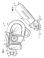
- FIG. 1 is a side elevational view of an example of a transfer tape dispenser constructed in accordance with the teachings of the present disclosure.
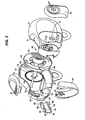
- FIG. 2 is an exploded isometric view of the transfer tape dispenser of Fig. 1.
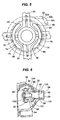
- FIG. 3 is an isometric view of a drive wheel of the transfer tape dispenser of Fig. 1.
- FIG. 4 is an isometric view from the opposite side of the drive wheel of FIG. 3.
- FIG. 6 is a fragmentary view of a portion of the transfer tape dispenser.
- FIG. 7 is a bottom elevational view of the transfer tape dispenser of Fig. 1.
- FIG. 8 not falling under the scope of protection of claim 1, is an isometric view of the transfer tape dispenser of Fig. 1 and showing the tape path.
- FIG. 9 is an isometric view of an alternate example an applicator tip, not falling under the scope of protection of claim 1, and a cushion body for a transfer tape dispenser constructed in accordance with the teachings of the present disclosure.
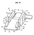
- FIG. 10 is an enlarged perspective view of the applicator tip of the transfer tape dispenser with structure to protect against the carrier tape folding over itself.
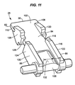
- FIG. 11 is a second perspective view of the applicator tip of FIG. 10.
- FIG. 12 is a perspective view of an alternate example of an applicator tip with structure to protect against the carrier tape folding over itself
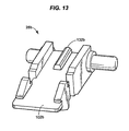
- FIG. 13 is a perspective view of an alternate example of an applicator tip with structure to protect against the carrier tape folding over itself.
- FIG. 14 is a perspective view of an alternate example of an applicator tip with structure to protect against the carrier tape folding over itself.
- FIG. 15 is a perspective view of an alternate example of an applicator tip with structure to protect against the carrier tape folding over itself
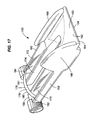
- FIG. 17 is a perspective view of an alternate example of an applicator tip with structure to protect against the carrier tape folding over itself.
- the transfer tape dispenser 20 includes a case 22, a supply spool 24, a return spool 26, and an applicator tip 28 having an application edge 30.
- the transfer tape dispenser 20 also includes a correction tape 32 having an application layer (not shown) and a carrier tape (not shown).
- a path of travel of the transfer tape 32 in the transfer tape dispenser 20 originates with the supply spool 24 and terminates with the return spool 26.
- a tape post 38 directs the transfer tape 32 from the supply spool 24 to the applicator tip 28, and from the applicator tip 28 to the return spool 26, respectively.
- the transfer tape dispenser 20 includes, in this example, a cushion body 94 that cushions the pressing of the application edge 30 on the surface 42.
- the transfer tape dispenser 20 further includes, in this example, a slip clutch mechanism 46 for providing slipping of the supply spool 24 relative to the rotation of the return spool 26, when necessary, to avoid the buildup of excessive tension in the transfer tape 32.
- the application layer (not shown) of the transfer tape 32 can provide numerous functions.
- the application layer (not shown) can be an adhesive material, a highlighting material, or a decorative coating material. Accordingly, one side of the application layer (not shown) can adhere to the surface 42, while the other side of the application layer (not shown) can provide a different functionality.
- the application layer (not shown) is a correction tape layer and is referred to as such.
- the correction tape layer (not shown) can be applied to a surface 42 to mask a portion of the surface 42 to which it is applied.
- the correction tape layer (not shown) is applied to one side of a carrier tape.
- the carrier tape consists of a flexible ribbon or strip of plastic or paper.
- the case 22 includes a first side 47 and a second side 49 that are attached together to house various components of the transfer tape dispenser 20.
- the two housings 47 and 49 of the case 22 are detachably attached together by a tongue 51 on the first side 47 that engages a groove 53 on the second side 49.
- the second side 49 includes a locking tab 55 that engages a corresponding aperture 57 in the first side 47.
- the case 22 can be shaped as desired. However, in the disclosed example, the case 22 is ergonomically shaped to provide comfort and intuitive operation when being operated by a user.
- the transfer tape dispenser 20 includes an index finger grip pad 31, a thumb grip pad 33, and an applicator tip cover 35 that is pivotally attached to the case 22.
- the index finger grip pad 31 is disposed on the upper part of the case 22 where a user would typically place his index finger when using the transfer tape dispenser 20.
- the grip pads 31 and 33 may either be part of the case 22 and constructed from the same material, or be independent grip pads of the same as or a different material that are attached to or formed on the case 22. In the disclosed example, the grip pads 31 and 33 are constructed from an elastomer and are attached to the case 22. Additionally, to provide sufficient grip between a user's finger and the grip pads 31 and 33 when holding the transfer tape dispenser 20, both grip pads 31 and 33 may be constructed from a soft plastic and may include a number of ridges 37 on their respective surfaces.
- the application tip cover 35 can be employed to protect the applicator tip 28 when not in use.
- the applicator tip cover 35 is generally shaped to correspond with the lateral cross sectional profile of the case 22.
- Each end 39 of the applicator tip cover 35 is pivotally attached to one of the first side 47 or the second side 49 of the case 22. Accordingly, the applicator tip cover 35 rotates about an axis (not shown) passing through the ends 39.
- the applicator tip cover 35 can be pivoted or rotated to the open position, as shown in Fig. 1.
- a user can rotate the applicator tip cover 35 in a direction 41 to a closed position (not shown) covering the tip 28.
- the case 22 includes a shaft 48 for mounting a drive wheel 50 inside the case 22.
- the drive wheel 50 includes a central hub 52 for being rotationally mounted on the shaft 48.
- the shaft 48 extends laterally and, in this example, from the second side 49 to first side 47. Accordingly, the drive wheel 50 can freely rotate about the shaft 48, but is prevented from moving or rotating in any other direction.
- the supply spool 24 is rotationally mounted on a supply side 58 of the drive wheel 50, and as will described in detail below can rotate with the drive wheel 50 or slip relative to the drive wheel 50 when necessary.
- the return spool 26 is disposed on a return side 60 of the drive wheel 50. In the disclosed example, the return spool 26 is an integral part of the drive wheel 50 and, therefore, rotates with the drive wheel 50.
- the return spool 26 is a circular ledge 62 that is integral with and protrudes outwardly from the return side 60 of the drive wheel 50.
- the circular ledge 62 is concentric with the drive wheel 50 and has a wider width than the width of the transfer tape 32. Accordingly, the circular ledge 62 defines the return spool 26 for collecting the carrier tape (not shown) of the transfer tape 32 in a winding manner, hence the return spool 26.
- a plurality of side walls 64 are provided around the circular ledge 62 to contain the transfer tape 32 on the return spool 26.
- the drive wheel 50 rotates in a dispensing direction 66 to unwind the transfer tape 32 from the supply spool 24.
- the carrier tape (not shown) is collected on the return spool 26 by being wound thereon when the drive wheel 50 rotates in the dispensing direction 66. Accordingly, the transfer tape 32 is dispensed by unwinding from the top of the supply spool 24 and is collected by being wound on the return spool 26 from the bottom thereof.
- the drive wheel 50 includes a number of flexible tabs 68 radially disposed on the return side 26 of the drive wheel 50 that engage a number of detents 70 radially disposed on the interior of the second side 49.
- the flexible tabs 68 include wedge shaped tips 72 that engage the detents 70, which are also wedge shaped. In the dispensing direction 66, the angled face of each wedge shaped tip 72 engages the angled face of a detent 70.
- the slip clutch mechanism 46 includes a pair of arcuate shoes 74 that have an outside diameter of generally similar size as the internal diameter of the supply spool 24.
- Each arcuate shoe 74 is attached to the hub 52 on the supply side 58 of the drive wheel 50 with a spoke 76.
- the arcuate shoes 74 partially define a supply hub 78 (shown with dashed lines), which is concentric with the hub 52, for mounting the supply spool 24 on the supply side 58 of the drive wheel 50.
- Each arcuate shoe 74 includes a pair of ridges 80 that extend across its width. The ridges 80 slightly protrude radially outward from the supply hub 78.
- the ridges 80 are distributed relative to the supply hub 78 in an evenly spaced radial manner. Accordingly, when the supply spool 24 is mounted on the supply hub 78, the ridges 80 cause the arcuate shoes 74 to flex and bias the ridges 80 against the internal periphery of the supply spool 24 to maintain frictional contact with the internal periphery of the supply spool 24.
- the transfer tape 32 When the diameter of the return spool 26 is larger than the diameter of the supply spool 24, the transfer tape 32 needs to unwind faster from the supply spool 24 than the speed by which is being wound on the return spool 26.
- the tension of the transfer tape 32 needs to be sufficient to overcome the frictional forces between the ridges 80 and the internal periphery of the supply spool 24 to provide faster rotation of the supply spool 24 relative to the drive wheel 50.
- the supply spool 24 must slip on the arcuate shoes 74 when necessary to synchronize the length of tape unwound from the supply spool 24 with the length of the tape wound on the return spool 26.
- the transfer tape 32 When the diameter of the return spool 26 is smaller than the diameter of the supply spool 24, the transfer tape 32 needs to unwind slower from the supply spool 24 than the speed by which is being wound on the return spool 26.
- the tension of the transfer tape 32 needs to be sufficient to overcome the frictional forces between the ridges 80 and the internal periphery of the supply spool 24 to provide slower rotation of the supply spool 24 relative to the drive wheel 50.
- the supply spool 24 must slip on the arcuate shoes 74 when necessary to synchronize the length of tape unwound from the supply spool 24 with the length of the tape wound on the return spool 26.
- the slip clutch mechanism operates by providing a slippable engagement between the drive wheel 50 and the supply spool 24.
- a variety of well known slip clutch mechanisms can be utilized for the transfer tape dispenser 20.
- a gasket, an o-ring, or a washer (not shown) that is constructed from a flexible material can be disposed on the hub 52 to frictionally engage the internal periphery of the supply spool 24.
- the hub 52 can include a plurality of detents (not shown) radially disposed thereon that can engage a plurality of detents (not shown) on the internal periphery of the supply spool 24.
- the applicator tip 28 is pivotally mounted inside the case 22.
- a portion 29 of the applicator tip 28, which includes the application edge 30, protrudes from the case 22 so that the tape 32 can be applied to a surface 42.
- the protruding portion 29 of the applicator tip 28, however, is wedge-shaped to guide the transfer tape 32 to and from the application edge 30.
- the transfer tape 32 travels from the supply spool 24 to reach an application side 84 of the applicator tip 28, travels around the application edge 30, and departs a non-application side 82 of the applicator tip 28 for the return spool 26.
- the disclosed applicator tip 28 is generally oriented near 90° relative to the orientation of the transfer tape 32 as it is unwound from the supply spool 24. Accordingly, in this example, the tape post 38 directs the transfer tape 32 from the supply spool 24 to the applicator tip 28, and also twists the transfer tape 32 to change its orientation in the path between the supply spool 24 and the applicator tip 28. Also, the tape post 38 directs the transfer tape 32 from the applicator tip 28 to the return spool 26, and also twists the carrier tape (not shown) to change its orientation in the tape path between the applicator tip 28 and the return spool 26.
- the supply tape post 38 can take on a variety of shapes and sizes in order to perform the described functions.
- the tape post 38 is a cylindrical rod that is mounted in the case and is generally parallel with the shaft 48.
- the transfer tape 32 is applied to a surface 42 by a user pressing the application side 84 of the application edge 30 on the surface 42 and moving the transfer tape dispenser 20 in a direction 88.
- the contact of the transfer tape 32 with the surface 42 at the application edge 30, combined with the movement of the transfer tape dispenser 20 in the direction 88, causes the transfer tape 32 to be pulled from the supply spool 24.
- the contact of the application edge 30 with the surface 42 causes the correction tape layer (not shown) of the transfer tape 32 to adhere to the surface 42 at the application edge 30.
- the return spool 26 rotates with the drive wheel 50, the carrier tape (not shown) is pulled by the return spool 26 and collected windingly thereon.
- moving the transfer tape dispenser 20 in the direction 88 applies the correction tape layer (not shown) and masks a portion of the surface 42 along the direction 88.
- the applicator tip 28 includes a pivot shaft 90 that is pivotally mounted in the case 22 to provide pivoting of the applicator tip 28 at the application edge 30 when being applied to a surface 42.
- the pivot shaft 90 is parallel with the application edge 30 and is pivotally mounted in a pair of forks 92 that protrude from the case 22. Accordingly, each end of the pivot shaft 90 pivots inside a corresponding fork 92 to provide pivoting of the applicator tip 28.
- the pivoting of the applicator tip 28 is limited and cushioned, in this example, by a cushion body 94 disposed between The applicator tip 28 and the first side 47 of the case 22.
- a cushion body 94 disposed between The applicator tip 28 and the first side 47 of the case 22.
- the applicator tip 28 pivots in a direction 93 as shown in FIG. 7.
- the guides 86 of the applicator tip 28 contact the cushion body 94, thus allowing the carrier tape to pass between the cushion body 94 and the non-application side 82 of the applicator tip 28.
- the pivoting of the applicator tip 28 from a rest position to an application position against the cushion body 94 causes the guides 86 to compresses the cushion body 94, which in turn reacts with a force that biases the applicator tip 28 back to the rest position. As the pivoting increases, the cushion body 94 is compressed further, which causes the force in the cushion 94 to also increase. Accordingly, a user can intuitively sense and determine how hard the application edge 30 can be pressed on a surface 42 for uniform application of the correction tape layer (not shown).
- the cushion body 94 also can provide cushioned pivoting of the applicator tip 28 when the application edge 30 is being applied to an uneven surface. Furthermore, the cushioned pivoting of the applicator tip 28 can compensate for any misalignment between the application edge 30 and a surface 42.
- the cushion body 94 may operate like a spring, a dampener or both.
- the cushion body 94 in this example, is a resilient body that when pressed in a direction provides a reaction force in an opposite direction.
- the cushion body 94 and the applicator tip 28 can be co-molded during manufacturing. Accordingly, the cushion body 94 is in one piece and includes a pair of cushion body sides 96 that are co-molded on the guides 86 and connected by a bridge 98. When co-molding the cushion body 94 with the applicator tip 28, the bridge 98 fits in a correspondingly sized indentation on the non-application side 82 of the applicator tip 28 so as to be positioned flush with the non-application side 82.
- the cushion body 94 may be connected to the applicator tip 28 by, for example, being co-molded with the applicator tip 28, as described above.
- the cushion body 94 may also be a discrete cushion body that is disposed between the applicator tip 28 and the case 22 without being connected to either the applicator tip 28 or the case 22.
- the cushion body 94 may also be connected to the case 22 without being connected to the applicator tip 28.
- the cushion body 94 in this example, is constructed from a different material than the applicator tip 28 and the case 22.
- the cushion body 94 is constructed as a one-piece elastomer body.
- the cushion body 94 is also shaped to fit between the applicator tip 28 and the case 22.
- the cushion body 94 and the applicator tip 28 can be co manufactured by, for example, an injection molding process.
- the cushion body 94 and the first side 47 of the case 22 can be co manufactured by, for example, an injection molding process.
- the applicator tip 28 particularly suited for use with the transfer tape dispenser 20 is disclosed.
- the applicator tip 28 includes a platform 102 that defines the application edge 30, a back edge 106, a left edge 108, a right edge 110, the application side 84 and the non-application side 82.
- Adjacent the left edge 108 is a first side wall 116.
- the first side wall 116 includes a groove 118 that divides the first side wall 116 into a forward portion 120 and a rear portion 122.
- Adjacent the right edge 110 is a second side wall 124.
- the second side wall 124 also includes a groove 126 that divides the second side wall 124 into a forward portion 128 and a rear portion 130.
- the application side 84 is the supply side surface
- the non-application side 82 is the return side surface. That is, the transfer tape 32 travels from the supply spool 24, over the application side 84, around the application edge 30, back across the non-application side 82, and back to the return spool 26.
- a protuberance 132 Extending up from the application side 32 of the applicator tip 20 is a protuberance 132.
- the protuberance 132 is in the shape of a portion of a cylinder.
- the protuberance 132 can extend up from the application surface 84 near the back edge 106.
- the protuberance as shown has a length approximately 1/3 of the distance between the application edge 30 and the back edge 106, and further has a width that is slightly less than the width W between the first side wall 116 and the second side wall 118. These dimensional specifications are merely examples, and other dimensions can be effective.
- a protuberance 132 may extend up from both the application side 84 and the non-application side 82.
- the transfer tape 32 has side edges 32a and 32b, and a middle portion 32c.
- the portion of the transfer tape 32 that is disposed over the protuberance 132 substantially takes the shape of the protuberance 132 by laying on top of it.
- the transfer tape 32 on the application surface 84 is maintained in a convex shape as it travels over the application surface 84 to the application edge 30.
- the side edges 32a and 32b are maintained adjacent the application side 84 of the applicator tip 20, and the middle portion 32c is forced upward by the protuberance 132.
- the transfer tape 32 has a tendency to fold up and over about itself along its length, i.e. the side edge 32a may fold up and about the middle portion 32c and over and on top of the opposing side edge 32b.
- This tendency can be exacerbated by designs in which the axis of rotation of the supply spool 24 is perpendicular to the application edge 30 such that the transfer tape 32 must twist or rotate 90° along its length as in the transfer tape dispenser 20.
- the protuberance 132 in forcing the transfer tape 32 into a convex shape, ensures that the transfer tape 32 cannot fold up and over itself along its length.
- Fig. 12 depicts an applicator tip 28a with a platform 102a and a protuberance 132a upstanding from the platform 102a.
- the protuberance 132a has the shape of a prism.
- the protuberance 132a can have a smoothly rounded top edge.
- Fig. 13 depicts an applicator 28b with a platform 102b and a protuberance 132b in the shape of a rail upstanding from the platform 102b.
- the protuberance 132b can include smoothly rounded edges adjacent the top surface.
- FIG. 14 and 15 depict applicator tips 28c and 28d with platforms 102c and 102d, respectively, and protuberances 132c and 132d in the shape of a series of posts 132c in the example shown in Fig. 14 and a single post, in the example shown in Fig. 15, upstanding from and extending down the respective platforms 102c and these examples, the posts can have a smoothly domed top.
- Other configurations can also be seen by one of ordinary skill in the art.
- the applicator tip 134 includes a platform 136 with a left sidewall 138 and a right sidewall 140. Extending inward from the left sidewall 138 of the applicator tip 134 is a left protuberance 142. Extending inward from the right sidewall 140 is right protuberance 144.' The right protuberance 144 can be similar to the left protuberance 142. A pair of channels 146, 148 arc defined between the platform 136 and the protuberances 142, 144. The side edges 32a, 32b of the transfer tape 32 can travel in the channels 146, 148 to ensure that the transfer tape 32 does not fold over itself.
- FIG. 17 A further example of an applicator tip 150 and a protuberance 151 is disclosed in Fig. 17.
- the applicator tip 150 is similar in construction to an applicator tip disclosed in U.S. Patent Application No. 10/663,073 .
- the applicator tip 150 includes a platform 152-that is defined by a front edge 154, a back edge 156, a left edge 158, a right edge 160, a top surface 162 and a bottom surface 164. Adjacent the left edge 158 is a first sidewall 166, and adjacent the right edge 160 is a second sidewall 168. In this example the sidewalls 166, 168 are curved over the platform 152 to help to maintain the correction tape on the platform 152. Further, the platform 152 includes a first leg 170 and a second leg 172 separated by a longitudinal slot 174 to impart flexibility to the platform 152.
- the protuberance 151 is defined by an arch 176 disposed near the back edge 156 on the top surface 162.
- the arch 176 has a convex surface 178 and a concave surface 180 and in this example serves the same purpose as the protuberance 132 in the previous example.
- the arch 176 includes a first end 182 attached to the first leg 170 and a second end 184 attached to the second leg 172 with the arch 176 spanning the slot 174.
- the transfer tape 32 is disposed over the convex surface 178 of the arch 176.
- the side edges 32a and 32b of the transfer tape are disposed near the first end 182 and second end 184, respectively, adjacent to the platform 152.
- the middle portion 32c rides along the convex surface 178 such that the transfer tape 32 is forced into a convex shape. This can help prevent the transfer tape 32 from folding over itself along its length.
- any structure that helps to maintain the side edges 32a, 32t of the correction tape 32 adjacent the platform and/or force the middle portion 32c o: the correction tape 32 upwards can be effective to prevent the correction tape 32 from folding over itself.
- any applicator tip with a protuberance can be useful with any transfer tape dispenser, not only those disclosed herein.
- the applicator tip can take on any configuration with respect to at least size, flexibility, manufacturing materials, or other parameters.
- the structure of the transfer tape dispenser 20 disclosed herein is only but one example of a dispenser that can be used with the application tip 28. Accordingly, the structure of the transfer tape dispenser 20 and its components can vary from that shown.
Landscapes
- Adhesive Tape Dispensing Devices (AREA)
- Registering, Tensioning, Guiding Webs, And Rollers Therefor (AREA)
- Fishing Rods (AREA)
- Road Signs Or Road Markings (AREA)
- Orthopedics, Nursing, And Contraception (AREA)
- Sewing Machines And Sewing (AREA)
- Electrophonic Musical Instruments (AREA)
- Pens And Brushes (AREA)
- Absorbent Articles And Supports Therefor (AREA)
- Coating Apparatus (AREA)
Claims (18)
- Système de pointe formant applicateur adapté pour diriger un ruban de transfert dans un dévidoir de ruban de transfert, le système comprenant :une pointe formant applicateur (28) comprenant une plateforme (102) avec un bord avant (30), un bord arrière (106), un premier bord latéral (108), un second bord latéral (110), une surface supérieure (84) et une surface inférieure (82), dans laquelle la surface supérieure, la surface inférieure, et le bord avant sont adaptés pour supporter un ruban de transfert (32), une première paroi (116) adjacente au premier bord latéral de la plateforme, une seconde paroi (124) adjacente au second bord latéral de la plateforme ; etau moins une saillie (132, 132a, 132b, 132c, 132d) s'étendant vers le haut depuis la surface supérieure de la pointe formant applicateur ; caractérisé en ce quela saillie s'étend d'un point adjacent au bord arrière vers le bord avant et est adaptée pour maintenir les bords externes (32a, 32b) du ruban de transfert de manière adjacente à la surface supérieure de la plateforme.
- Système de pointe selon la revendication 1, dans lequel la saillie est une partie d'un cylindre (132) s'étendant vers le haut depuis la surface supérieure de la plateforme et adaptée pour maintenir le ruban de transfert dans une configuration convexe, lorsqu'il est observé depuis le dessus de la surface supérieure de la plateforme.
- Système de pointe selon la revendication 1, dans lequel la saillie est un rail (132a, 132b) s'étendant vers le haut depuis la surface supérieure de la plateforme et adapté pour maintenir le ruban de transfert dans une configuration convexe, lorsqu'il est observé depuis le dessus de la surface supérieure de la plateforme.
- Système de pointe selon la revendication 1, dans lequel la saillie est une série de montants (132c) s'étendant vers le haut depuis la surface supérieure de la plateforme et adaptés pour maintenir le ruban de transfert dans une configuration convexe, lorsqu'il est observé depuis le dessus de la surface supérieure de la plateforme.
- Système de pointe selon la revendication 1, dans lequel la saillie est un montant unique (132d) s'étendant vers le haut depuis la surface supérieure de la plateforme et adapté pour maintenir le ruban de transfert dans une configuration convexe, lorsqu'il est observé depuis le dessus de la surface supérieure de la plateforme.
- Système de pointe selon la revendication 1, dans lequel la saillie est une arche (176) s'étendant vers le haut depuis la surface supérieure de la plateforme et adaptée pour maintenir le ruban de transfert dans une configuration convexe, lorsqu'il est observé depuis le dessus de la surface supérieure de la plateforme.
- Système de pointe selon la revendication 1, dans lequel chaque paroi latérale comprend une rainure (118, 126) qui définit une partie avant respective (120, 128) et une partie arrière respective (122, 130) de chaque paroi latérale.
- Système de pointe selon la revendication 1, dans lequel les parois latérales (166, 168) sont incurvées sur la plateforme.
- Système de pointe selon la revendication 1, dans lequel la plateforme comprend une première patte (170) et une seconde patte (172) séparées par une fente (174).
- Système de pointe selon la revendication 9, dans lequel la saillie est une arche (176) avec une première extrémité (182) et une seconde extrémité (184), la première extrémité étant reliée à la première patte, la seconde extrémité étant reliée à la seconde patte, l'arche comprenant une surface convexe (178) opposée à la plateforme, la surface convexe étant adaptée pour maintenir le ruban de transfert dans une configuration convexe, lorsqu'il est observé depuis le dessus de la surface supérieure de la plateforme.
- Système de pointe selon la revendication 1, comprenant en outre :un boîtier (22) ;une bobine débitrice (24) disposée de manière orientable à l'intérieur du boîtier ;une bobine réceptrice (26) disposée de manière orientable à l'intérieur du boîtier ;un ruban de transfert (32) avec une première extrémité et une seconde extrémité, dans lequel la première extrémité est reliée à la bobine débitrice, et la seconde extrémité est reliée à la bobine réceptrice ;dans lequel la pointe formant applicateur est disposée en partie à l'intérieur du boîtier, et le ruban de transfert se déplace de la bobine débitrice, autour du bord avant de la pointe formant applicateur, jusqu'à la bobine réceptrice.
- Système de pointe selon la revendication 11, dans lequel l'axe de rotation de la bobine débitrice n'est pas parallèle au bord avant de la pointe formant applicateur.
- Système de pointe selon la revendication 12, dans lequel l'axe de rotation de la bobine débitrice est approximativement perpendiculaire au bord avant de la pointe formant applicateur.
- Système de pointe selon la revendication 11, comprenant en outre un corps amortisseur (94) situé sur la pointe formant applicateur pour amortir la force de la pointe formant applicateur contre le boîtier en cours d'utilisation.
- Système de pointe selon la revendication 14, dans lequel la pointe formant applicateur est fixée de manière orientable au boîtier.
- Système de pointe selon la revendication 11, dans lequel la saillie est une partie d'un cylindre s'étendant vers le haut depuis la surface supérieure de la plateforme et adaptée pour maintenir le ruban de transfert dans la configuration convexe, lorsqu'il est observé depuis le dessus de la surface supérieure de la plateforme.
- Système de pointe selon la revendication 11, dans lequel la saillie est un rail s'étendant vers le haut depuis la surface supérieure de la plateforme et adapté pour maintenir le ruban de transfert dans une configuration convexe, lorsqu'il est observé depuis le dessus de la surface supérieure de la plateforme.
- Système de pointe selon la revendication 11, dans lequel la saillie est une série de montants s'étendant vers le haut depuis la surface supérieure de la plateforme et adaptés pour maintenir le ruban de transfert dans une configuration convexe, lorsqu'il est observé depuis le dessus de la surface supérieure de la plateforme.
Priority Applications (2)
| Application Number | Priority Date | Filing Date | Title |
|---|---|---|---|
| PL04776944T PL1708944T3 (pl) | 2004-01-13 | 2004-06-22 | Końcówka aplikatora taśmy korekcyjnej mająca walcowy występ |
| EP07015989A EP1849728B1 (fr) | 2004-01-13 | 2004-06-22 | Pointe formant applicateur de bande de correction |
Applications Claiming Priority (2)
| Application Number | Priority Date | Filing Date | Title |
|---|---|---|---|
| US10/756,042 US7163040B2 (en) | 2004-01-13 | 2004-01-13 | Correction tape applicator tip with cylindrical projection |
| PCT/US2004/020055 WO2005070798A1 (fr) | 2004-01-13 | 2004-06-22 | Pointe formant applicateur de bande de correction presentant une saillie cylindrique |
Related Child Applications (1)
| Application Number | Title | Priority Date | Filing Date |
|---|---|---|---|
| EP07015989A Division EP1849728B1 (fr) | 2004-01-13 | 2004-06-22 | Pointe formant applicateur de bande de correction |
Publications (2)
| Publication Number | Publication Date |
|---|---|
| EP1708944A1 EP1708944A1 (fr) | 2006-10-11 |
| EP1708944B1 true EP1708944B1 (fr) | 2007-08-15 |
Family
ID=34739738
Family Applications (2)
| Application Number | Title | Priority Date | Filing Date |
|---|---|---|---|
| EP07015989A Expired - Lifetime EP1849728B1 (fr) | 2004-01-13 | 2004-06-22 | Pointe formant applicateur de bande de correction |
| EP04776944A Expired - Lifetime EP1708944B1 (fr) | 2004-01-13 | 2004-06-22 | Pointe formant applicateur de bande de correction presentant une saillie cylindrique |
Family Applications Before (1)
| Application Number | Title | Priority Date | Filing Date |
|---|---|---|---|
| EP07015989A Expired - Lifetime EP1849728B1 (fr) | 2004-01-13 | 2004-06-22 | Pointe formant applicateur de bande de correction |
Country Status (12)
| Country | Link |
|---|---|
| US (2) | US7163040B2 (fr) |
| EP (2) | EP1849728B1 (fr) |
| JP (1) | JP4588718B2 (fr) |
| CN (1) | CN100594171C (fr) |
| AT (2) | ATE370091T1 (fr) |
| BR (1) | BRPI0418394A (fr) |
| CA (1) | CA2553298A1 (fr) |
| DE (2) | DE602004031161D1 (fr) |
| ES (1) | ES2291944T3 (fr) |
| PL (1) | PL1708944T3 (fr) |
| TW (1) | TW200523196A (fr) |
| WO (1) | WO2005070798A1 (fr) |
Families Citing this family (24)
| Publication number | Priority date | Publication date | Assignee | Title |
|---|---|---|---|---|
| JP4750388B2 (ja) * | 2004-08-11 | 2011-08-17 | 株式会社壽 | カバー付きディスペンサー |
| JP4769964B2 (ja) * | 2006-02-06 | 2011-09-07 | フジコピアン株式会社 | 塗膜転写具 |
| DE102006031173B4 (de) * | 2006-07-06 | 2011-04-14 | Henkel Ag & Co. Kgaa | Vorrichtung zum Übertragen eines Films von einem Trägerband auf ein Substrat |
| JP2008162052A (ja) * | 2006-12-27 | 2008-07-17 | Kokuyo Co Ltd | 転写具 |
| JP5070567B2 (ja) * | 2006-12-27 | 2012-11-14 | コクヨ株式会社 | 転写具 |
| US20090090470A1 (en) * | 2007-10-08 | 2009-04-09 | Ming-Hua Yen | Coating film transfer tool and its tape transfer head |
| EP2070857B1 (fr) * | 2007-12-14 | 2013-02-13 | Société BIC | Dispositif portatif pour appliquer un dépôt, par exemple un matériau adhésif, à revêtement ou coloré sur une surface de correction |
| US20090179061A1 (en) * | 2008-01-11 | 2009-07-16 | Henkel Corporation | Adhesive tape dispenser and applicator |
| JP4899023B2 (ja) * | 2008-07-16 | 2012-03-21 | コクヨ株式会社 | 転写具 |
| US20100018653A1 (en) * | 2008-07-25 | 2010-01-28 | Henkel Corporation | Adhesive tape dispenser and applicator |
| US8146644B2 (en) | 2009-05-14 | 2012-04-03 | Sdi Corporation | Film transfer tool with application head moveable between exposed and stowed positions |
| US20110042506A1 (en) * | 2009-08-19 | 2011-02-24 | Chien-Lung Wu | Device for Changing Orientation of Tape of Tape Transfer Device |
| US8397784B2 (en) | 2010-08-31 | 2013-03-19 | Sanford, L.P. | Correction tape dispenser with variable clutch mechanism |
| US8746313B2 (en) | 2010-12-29 | 2014-06-10 | Sanford, L.P. | Correction tape re-tensioning mechanism and correction tape dispenser comprising same |
| US8578999B2 (en) | 2010-12-29 | 2013-11-12 | Sanford, L.P. | Variable clutch mechanism and correction tape dispenser with variable clutch mechanism |
| KR101244800B1 (ko) * | 2011-09-19 | 2013-03-18 | (주)세줄 | 수정테이프 디스펜서 |
| FR2981057B1 (fr) * | 2011-10-10 | 2013-11-29 | Bic Soc | Dispositif manuel d'application par ruban d'un revetement sur un support a embout ameliore |
| US8746316B2 (en) | 2011-12-30 | 2014-06-10 | Sanford, L.P. | Variable clutch mechanism and correction tape dispenser with variable clutch mechanism |
| JP6247199B2 (ja) | 2014-12-09 | 2017-12-13 | 株式会社トンボ鉛筆 | 塗膜転写具 |
| FR3046786B1 (fr) | 2016-01-15 | 2018-02-09 | Societe Bic | Dispositif manuel d'application par ruban d'un revetement sur un support presentant un embout d'application ameliore |
| JP7095856B2 (ja) | 2017-07-04 | 2022-07-05 | 株式会社トンボ鉛筆 | 塗膜転写具 |
| WO2019008687A1 (fr) * | 2017-07-04 | 2019-01-10 | 株式会社トンボ鉛筆 | Outil de transfert de film de revêtement |
| JP6898642B2 (ja) * | 2017-08-01 | 2021-07-07 | プラス株式会社 | 塗膜転写具 |
| USD1054021S1 (en) * | 2022-05-10 | 2024-12-10 | Shl Medical Ag | Medical injector support pad |
Family Cites Families (72)
| Publication number | Priority date | Publication date | Assignee | Title |
|---|---|---|---|---|
| US3774309A (en) | 1972-06-19 | 1973-11-27 | N Leopoldi | Steel measuring tape holder |
| US4341585A (en) | 1980-02-15 | 1982-07-27 | Minnesota Mining And Manufacturing Company | Devices for imparting curl to tapes |
| US4315047A (en) | 1980-02-15 | 1982-02-09 | Minnesota Mining And Manufacturing Company | Curled tape, roll, and container end |
| US4591407A (en) | 1985-05-22 | 1986-05-27 | Minnesota Mining And Manufacturing Company | Tape applicator |
| DE3638722A1 (de) | 1986-11-13 | 1988-05-26 | Pelikan Ag | Geraet zum auftragen eines klebstoff-filmes |
| US4748746A (en) | 1987-01-15 | 1988-06-07 | Great Neck Saw Manufacturers, Inc. | Recoilable tape shock absorber |
| DE3736367C1 (de) | 1987-10-27 | 1989-02-23 | Pelikan Ag | Handgeraet zum UEbertragen eines Filmes von einer Traegerfolie auf ein Substrat |
| JP2857922B2 (ja) * | 1990-09-25 | 1999-02-17 | ゼネラル株式会社 | テープ使用被覆剤転写具 |
| EP1357481A3 (fr) | 1991-03-07 | 2005-04-27 | Masimo Corporation | Appareil et procédé de traitement de signal |
| US5995855A (en) | 1998-02-11 | 1999-11-30 | Masimo Corporation | Pulse oximetry sensor adapter |
| CA2119865A1 (fr) | 1991-10-02 | 1993-04-15 | Fujicopian Co., Ltd. | Appareil de transfert de couches de recouvrement |
| JPH05178525A (ja) * | 1991-12-26 | 1993-07-20 | Fujicopian Co Ltd | 塗膜転写具 |
| US5210956A (en) | 1992-03-03 | 1993-05-18 | Arrow Fastener Company, Inc. | Retractable tape measure |
| US5393368A (en) | 1993-02-10 | 1995-02-28 | The Gillette Company | Correction tape dispenser |
| JP2807805B2 (ja) | 1993-09-22 | 1998-10-08 | シードゴム工業株式会社 | 塗膜転写具 |
| US6371921B1 (en) | 1994-04-15 | 2002-04-16 | Masimo Corporation | System and method of determining whether to recalibrate a blood pressure monitor |
| JP2869855B2 (ja) | 1995-03-28 | 1999-03-10 | 株式会社トンボ鉛筆 | 字消し具 |
| US6931268B1 (en) | 1995-06-07 | 2005-08-16 | Masimo Laboratories, Inc. | Active pulse blood constituent monitoring |
| DE19604056C1 (de) * | 1996-02-05 | 1997-07-24 | Pritt Produktionsgesellschaft | Handgerät zum Übertragen eines Films von einer Trägerfolie auf ein Substrat |
| DE19606626C2 (de) | 1996-02-22 | 1998-05-20 | Pritt Produktionsgesellschaft | Reibungsbremse für einen Dispenser zur drehmomentbegrenzenden Kraftübertragung zwischen einem Spulenkern einer Spule zum Auf- oder Abwickeln eines Bandes und einer Drehaufnahme |
| US6027452A (en) | 1996-06-26 | 2000-02-22 | Vital Insite, Inc. | Rapid non-invasive blood pressure measuring device |
| JP3698850B2 (ja) * | 1997-02-19 | 2005-09-21 | ゼネラル株式会社 | 感圧転写具 |
| US5795085A (en) | 1997-03-05 | 1998-08-18 | Yoo; Kwang-Ho | Correction tape |
| US6229856B1 (en) | 1997-04-14 | 2001-05-08 | Masimo Corporation | Method and apparatus for demodulating signals in a pulse oximetry system |
| JP3716379B2 (ja) * | 1997-04-30 | 2005-11-16 | 株式会社トンボ鉛筆 | 塗布具の転写ヘッド |
| US6321816B1 (en) * | 1997-06-30 | 2001-11-27 | Kores Holding Zug Ag | Reel arrangement |
| US5899619A (en) | 1997-11-14 | 1999-05-04 | May O'Shei | Hand held marking device |
| JPH11157290A (ja) * | 1997-12-01 | 1999-06-15 | Sakura Color Prod Corp | 転写具 |
| JPH11157291A (ja) * | 1997-12-01 | 1999-06-15 | Sakura Color Prod Corp | 転写具 |
| US6148534A (en) | 1997-12-11 | 2000-11-21 | Li; Shih Lin | Tape rule with an elaborate buffer |
| JPH11227385A (ja) | 1998-02-12 | 1999-08-24 | Fujicopian Co Ltd | 塗膜転写具 |
| US6525386B1 (en) | 1998-03-10 | 2003-02-25 | Masimo Corporation | Non-protruding optoelectronic lens |
| US6273162B1 (en) | 1998-04-10 | 2001-08-14 | Sumitomo Rubber Industries, Ltd. | Pneumatic tire with specified bead portion |
| EP2319398B1 (fr) | 1998-06-03 | 2019-01-16 | Masimo Corporation | Stéréo-oxymètre de pouls |
| TR200100127T2 (tr) | 1998-08-19 | 2001-06-21 | Pritt Produktionsgesellschaft Mbh | Taşıyıcı bir bant üzerine yerleştirilmiş film haldeki maddenin bir alt tabakaya transferi için alet |
| DK1105331T3 (da) * | 1998-08-19 | 2003-09-15 | Pritt Produktionsgesellschaft | Apparat til overføring af et materiale, der i form af en film er anbragt på et bærebånd, til et substrat |
| JP2995659B1 (ja) | 1998-09-18 | 1999-12-27 | 株式会社トンボ鉛筆 | 塗膜転写具 |
| JP3503052B2 (ja) | 1998-09-25 | 2004-03-02 | 株式会社トンボ鉛筆 | 塗膜転写具における転写ヘッド |
| US6463311B1 (en) | 1998-12-30 | 2002-10-08 | Masimo Corporation | Plethysmograph pulse recognition processor |
| US6684090B2 (en) | 1999-01-07 | 2004-01-27 | Masimo Corporation | Pulse oximetry data confidence indicator |
| JP2000343890A (ja) | 1999-06-07 | 2000-12-12 | Fujicopian Co Ltd | 塗膜転写具 |
| US6324769B1 (en) | 1999-08-04 | 2001-12-04 | The Stanley Works | Rule assembly with increased blade standout |
| US6515273B2 (en) | 1999-08-26 | 2003-02-04 | Masimo Corporation | System for indicating the expiration of the useful operating life of a pulse oximetry sensor |
| US6601631B1 (en) | 1999-09-07 | 2003-08-05 | Berol Corporation | Dispenser for applying a material to a surface |
| US6321815B1 (en) | 1999-09-24 | 2001-11-27 | Kwang-Ho You | Protector for leading end of correction tape |
| US6943348B1 (en) | 1999-10-19 | 2005-09-13 | Masimo Corporation | System for detecting injection holding material |
| JP2001138690A (ja) | 1999-11-15 | 2001-05-22 | Tombow Pencil Co Ltd | 塗布具 |
| US6950687B2 (en) | 1999-12-09 | 2005-09-27 | Masimo Corporation | Isolation and communication element for a resposable pulse oximetry sensor |
| US6377829B1 (en) | 1999-12-09 | 2002-04-23 | Masimo Corporation | Resposable pulse oximetry sensor |
| CN1178830C (zh) | 2000-02-25 | 2004-12-08 | Bic学会 | 手持式装置 |
| JP4316770B2 (ja) * | 2000-05-08 | 2009-08-19 | 株式会社トンボ鉛筆 | 塗膜転写具 |
| US6430525B1 (en) | 2000-06-05 | 2002-08-06 | Masimo Corporation | Variable mode averager |
| US6454856B1 (en) * | 2000-07-17 | 2002-09-24 | Gye Ho Jung | Structure of winding correction tape in correction tape adhesive |
| ES2353056T3 (es) * | 2001-04-09 | 2011-02-25 | SOCIéTé BIC | Aparato de mano para transmitir una película a un sustrato y que contiene un aplicador que comprende una pluralidad de bordes de aplicación. |
| WO2002089664A2 (fr) | 2001-05-03 | 2002-11-14 | Masimo Corporation | Detecteur optique protege par un circuit souple |
| US6461068B1 (en) | 2001-06-07 | 2002-10-08 | Robert Holmes | Correction tape equipped writing instruments |
| US6850787B2 (en) | 2001-06-29 | 2005-02-01 | Masimo Laboratories, Inc. | Signal component processor |
| EP1295834B1 (fr) | 2001-09-19 | 2008-05-21 | Société BIC | Dispositif manuel pour appliquer sur un substrat un film d'un matériau adhésif, de revêtement ou coloré |
| US6934570B2 (en) | 2002-01-08 | 2005-08-23 | Masimo Corporation | Physiological sensor combination |
| US6822564B2 (en) | 2002-01-24 | 2004-11-23 | Masimo Corporation | Parallel measurement alarm processor |
| US7015451B2 (en) | 2002-01-25 | 2006-03-21 | Masimo Corporation | Power supply rail controller |
| US6961598B2 (en) | 2002-02-22 | 2005-11-01 | Masimo Corporation | Pulse and active pulse spectraphotometry |
| US6850788B2 (en) | 2002-03-25 | 2005-02-01 | Masimo Corporation | Physiological measurement communications adapter |
| DE10214604B4 (de) | 2002-04-03 | 2005-10-06 | Henkel Kgaa | Gerät zum Übertragen eines in Form eines Filmes auf ein Trägerband aufgebrachten Stoffes auf ein Substrat |
| US7152650B2 (en) * | 2003-02-15 | 2006-12-26 | Henkel Consumer Adhesives, Inc. | Tape dispenser |
| JP2004066688A (ja) * | 2002-08-07 | 2004-03-04 | Tombow Pencil Co Ltd | 塗膜転写具 |
| WO2004047631A2 (fr) | 2002-11-22 | 2004-06-10 | Masimo Laboratories, Inc. | Systeme de mesure d'un parametre sanguin |
| US6970792B1 (en) | 2002-12-04 | 2005-11-29 | Masimo Laboratories, Inc. | Systems and methods for determining blood oxygen saturation values using complex number encoding |
| US6920345B2 (en) | 2003-01-24 | 2005-07-19 | Masimo Corporation | Optical sensor including disposable and reusable elements |
| US7093640B2 (en) * | 2003-02-10 | 2006-08-22 | Kitaru Innovations, Inc. | Tape dispenser having a retaining and application area |
| US7003338B2 (en) | 2003-07-08 | 2006-02-21 | Masimo Corporation | Method and apparatus for reducing coupling between signals |
| USD491986S1 (en) | 2003-09-05 | 2004-06-22 | Charles E. Bain | Correction tape dispenser |
-
2004
- 2004-01-13 US US10/756,042 patent/US7163040B2/en not_active Expired - Lifetime
- 2004-06-22 EP EP07015989A patent/EP1849728B1/fr not_active Expired - Lifetime
- 2004-06-22 CN CN200480042437A patent/CN100594171C/zh not_active Expired - Fee Related
- 2004-06-22 ES ES04776944T patent/ES2291944T3/es not_active Expired - Lifetime
- 2004-06-22 DE DE602004031161T patent/DE602004031161D1/de not_active Expired - Lifetime
- 2004-06-22 AT AT04776944T patent/ATE370091T1/de not_active IP Right Cessation
- 2004-06-22 DE DE602004008344T patent/DE602004008344T2/de not_active Expired - Fee Related
- 2004-06-22 JP JP2006549225A patent/JP4588718B2/ja not_active Expired - Fee Related
- 2004-06-22 PL PL04776944T patent/PL1708944T3/pl unknown
- 2004-06-22 BR BRPI0418394-0A patent/BRPI0418394A/pt not_active IP Right Cessation
- 2004-06-22 EP EP04776944A patent/EP1708944B1/fr not_active Expired - Lifetime
- 2004-06-22 WO PCT/US2004/020055 patent/WO2005070798A1/fr not_active Ceased
- 2004-06-22 CA CA002553298A patent/CA2553298A1/fr not_active Abandoned
- 2004-06-22 AT AT07015989T patent/ATE495994T1/de not_active IP Right Cessation
- 2004-07-06 TW TW093120239A patent/TW200523196A/zh unknown
-
2006
- 2006-12-29 US US11/618,596 patent/US7681616B2/en not_active Expired - Fee Related
Non-Patent Citations (1)
| Title |
|---|
| None * |
Also Published As
| Publication number | Publication date |
|---|---|
| EP1849728A2 (fr) | 2007-10-31 |
| DE602004031161D1 (de) | 2011-03-03 |
| TW200523196A (en) | 2005-07-16 |
| US20050150606A1 (en) | 2005-07-14 |
| CA2553298A1 (fr) | 2005-08-04 |
| US7163040B2 (en) | 2007-01-16 |
| PL1708944T3 (pl) | 2008-01-31 |
| JP4588718B2 (ja) | 2010-12-01 |
| CN1926039A (zh) | 2007-03-07 |
| ATE495994T1 (de) | 2011-02-15 |
| EP1708944A1 (fr) | 2006-10-11 |
| CN100594171C (zh) | 2010-03-17 |
| ATE370091T1 (de) | 2007-09-15 |
| EP1849728B1 (fr) | 2011-01-19 |
| WO2005070798A1 (fr) | 2005-08-04 |
| JP2007517695A (ja) | 2007-07-05 |
| ES2291944T3 (es) | 2008-03-01 |
| BRPI0418394A (pt) | 2007-06-05 |
| DE602004008344T2 (de) | 2007-11-29 |
| US7681616B2 (en) | 2010-03-23 |
| US20070107851A1 (en) | 2007-05-17 |
| DE602004008344D1 (de) | 2007-09-27 |
| EP1849728A3 (fr) | 2008-01-23 |
Similar Documents
| Publication | Publication Date | Title |
|---|---|---|
| EP1849728B1 (fr) | Pointe formant applicateur de bande de correction | |
| US7228882B2 (en) | Tape dispenser with a cushioned applicator tip | |
| US6997229B2 (en) | Rotatable applicator tip for a corrective tape dispenser | |
| US6874554B2 (en) | Tape dispenser having a tape retaining and application area | |
| US20070175589A1 (en) | Transfer devices | |
| US8746313B2 (en) | Correction tape re-tensioning mechanism and correction tape dispenser comprising same | |
| KR20020044138A (ko) | 재료를 표면에 가하는 디스펜서 | |
| HK1104021A (en) | Correction tape applicator tip with cylindrical projection | |
| HK1097498A (en) | Tape dispenser with a cushioned applicator tip | |
| MXPA06008038A (en) | Correction tape applicator tip with cylindrical projection | |
| US20050056375A1 (en) | Applicator tip for a corrective tape dispenser | |
| JPH0586953U (ja) | 転写式修正具 | |
| WO2005035411A1 (fr) | Pointe d'application destinee a un distributeur de ruban correcteur | |
| EP1688380B1 (fr) | Dispositifs de transfert | |
| HK1096076B (en) | Rotatable applicator tip for a corrective tape dispenser and a transfer tape dispenser |
Legal Events
| Date | Code | Title | Description |
|---|---|---|---|
| PUAI | Public reference made under article 153(3) epc to a published international application that has entered the european phase |
Free format text: ORIGINAL CODE: 0009012 |
|
| 17P | Request for examination filed |
Effective date: 20060703 |
|
| AK | Designated contracting states |
Kind code of ref document: A1 Designated state(s): AT BE BG CH CY CZ DE DK EE ES FI FR GB GR HU IE IT LI LU MC NL PL PT RO SE SI SK TR |
|
| GRAP | Despatch of communication of intention to grant a patent |
Free format text: ORIGINAL CODE: EPIDOSNIGR1 |
|
| GRAS | Grant fee paid |
Free format text: ORIGINAL CODE: EPIDOSNIGR3 |
|
| DAX | Request for extension of the european patent (deleted) | ||
| GRAA | (expected) grant |
Free format text: ORIGINAL CODE: 0009210 |
|
| AK | Designated contracting states |
Kind code of ref document: B1 Designated state(s): AT BE BG CH CY CZ DE DK EE ES FI FR GB GR HU IE IT LI LU MC NL PL PT RO SE SI SK TR |
|
| REG | Reference to a national code |
Ref country code: GB Ref legal event code: FG4D |
|
| REG | Reference to a national code |
Ref country code: CH Ref legal event code: EP |
|
| REG | Reference to a national code |
Ref country code: IE Ref legal event code: FG4D |
|
| REF | Corresponds to: |
Ref document number: 602004008344 Country of ref document: DE Date of ref document: 20070927 Kind code of ref document: P |
|
| ET | Fr: translation filed | ||
| PG25 | Lapsed in a contracting state [announced via postgrant information from national office to epo] |
Ref country code: BG Free format text: LAPSE BECAUSE OF FAILURE TO SUBMIT A TRANSLATION OF THE DESCRIPTION OR TO PAY THE FEE WITHIN THE PRESCRIBED TIME-LIMIT Effective date: 20071115 Ref country code: FI Free format text: LAPSE BECAUSE OF FAILURE TO SUBMIT A TRANSLATION OF THE DESCRIPTION OR TO PAY THE FEE WITHIN THE PRESCRIBED TIME-LIMIT Effective date: 20070815 |
|
| REG | Reference to a national code |
Ref country code: PL Ref legal event code: T3 |
|
| PG25 | Lapsed in a contracting state [announced via postgrant information from national office to epo] |
Ref country code: LI Free format text: LAPSE BECAUSE OF FAILURE TO SUBMIT A TRANSLATION OF THE DESCRIPTION OR TO PAY THE FEE WITHIN THE PRESCRIBED TIME-LIMIT Effective date: 20070815 Ref country code: AT Free format text: LAPSE BECAUSE OF FAILURE TO SUBMIT A TRANSLATION OF THE DESCRIPTION OR TO PAY THE FEE WITHIN THE PRESCRIBED TIME-LIMIT Effective date: 20070815 Ref country code: CH Free format text: LAPSE BECAUSE OF FAILURE TO SUBMIT A TRANSLATION OF THE DESCRIPTION OR TO PAY THE FEE WITHIN THE PRESCRIBED TIME-LIMIT Effective date: 20070815 |
|
| REG | Reference to a national code |
Ref country code: CH Ref legal event code: PL |
|
| REG | Reference to a national code |
Ref country code: ES Ref legal event code: FG2A Ref document number: 2291944 Country of ref document: ES Kind code of ref document: T3 |
|
| PG25 | Lapsed in a contracting state [announced via postgrant information from national office to epo] |
Ref country code: DK Free format text: LAPSE BECAUSE OF FAILURE TO SUBMIT A TRANSLATION OF THE DESCRIPTION OR TO PAY THE FEE WITHIN THE PRESCRIBED TIME-LIMIT Effective date: 20070815 Ref country code: GR Free format text: LAPSE BECAUSE OF FAILURE TO SUBMIT A TRANSLATION OF THE DESCRIPTION OR TO PAY THE FEE WITHIN THE PRESCRIBED TIME-LIMIT Effective date: 20071116 |
|
| PG25 | Lapsed in a contracting state [announced via postgrant information from national office to epo] |
Ref country code: SK Free format text: LAPSE BECAUSE OF FAILURE TO SUBMIT A TRANSLATION OF THE DESCRIPTION OR TO PAY THE FEE WITHIN THE PRESCRIBED TIME-LIMIT Effective date: 20070815 Ref country code: PT Free format text: LAPSE BECAUSE OF FAILURE TO SUBMIT A TRANSLATION OF THE DESCRIPTION OR TO PAY THE FEE WITHIN THE PRESCRIBED TIME-LIMIT Effective date: 20080115 Ref country code: CZ Free format text: LAPSE BECAUSE OF FAILURE TO SUBMIT A TRANSLATION OF THE DESCRIPTION OR TO PAY THE FEE WITHIN THE PRESCRIBED TIME-LIMIT Effective date: 20070815 |
|
| PLBE | No opposition filed within time limit |
Free format text: ORIGINAL CODE: 0009261 |
|
| STAA | Information on the status of an ep patent application or granted ep patent |
Free format text: STATUS: NO OPPOSITION FILED WITHIN TIME LIMIT |
|
| PG25 | Lapsed in a contracting state [announced via postgrant information from national office to epo] |
Ref country code: RO Free format text: LAPSE BECAUSE OF FAILURE TO SUBMIT A TRANSLATION OF THE DESCRIPTION OR TO PAY THE FEE WITHIN THE PRESCRIBED TIME-LIMIT Effective date: 20070815 Ref country code: SE Free format text: LAPSE BECAUSE OF FAILURE TO SUBMIT A TRANSLATION OF THE DESCRIPTION OR TO PAY THE FEE WITHIN THE PRESCRIBED TIME-LIMIT Effective date: 20071115 |
|
| 26N | No opposition filed |
Effective date: 20080516 |
|
| PGFP | Annual fee paid to national office [announced via postgrant information from national office to epo] |
Ref country code: ES Payment date: 20080626 Year of fee payment: 5 |
|
| PGFP | Annual fee paid to national office [announced via postgrant information from national office to epo] |
Ref country code: NL Payment date: 20080624 Year of fee payment: 5 |
|
| PG25 | Lapsed in a contracting state [announced via postgrant information from national office to epo] |
Ref country code: MC Free format text: LAPSE BECAUSE OF NON-PAYMENT OF DUE FEES Effective date: 20080630 |
|
| PGFP | Annual fee paid to national office [announced via postgrant information from national office to epo] |
Ref country code: BE Payment date: 20080730 Year of fee payment: 5 |
|
| PG25 | Lapsed in a contracting state [announced via postgrant information from national office to epo] |
Ref country code: IE Free format text: LAPSE BECAUSE OF NON-PAYMENT OF DUE FEES Effective date: 20080623 Ref country code: EE Free format text: LAPSE BECAUSE OF FAILURE TO SUBMIT A TRANSLATION OF THE DESCRIPTION OR TO PAY THE FEE WITHIN THE PRESCRIBED TIME-LIMIT Effective date: 20070815 |
|
| PG25 | Lapsed in a contracting state [announced via postgrant information from national office to epo] |
Ref country code: SI Free format text: LAPSE BECAUSE OF FAILURE TO SUBMIT A TRANSLATION OF THE DESCRIPTION OR TO PAY THE FEE WITHIN THE PRESCRIBED TIME-LIMIT Effective date: 20070815 |
|
| PG25 | Lapsed in a contracting state [announced via postgrant information from national office to epo] |
Ref country code: CY Free format text: LAPSE BECAUSE OF FAILURE TO SUBMIT A TRANSLATION OF THE DESCRIPTION OR TO PAY THE FEE WITHIN THE PRESCRIBED TIME-LIMIT Effective date: 20070815 |
|
| PGFP | Annual fee paid to national office [announced via postgrant information from national office to epo] |
Ref country code: IT Payment date: 20090625 Year of fee payment: 6 Ref country code: PL Payment date: 20090608 Year of fee payment: 6 |
|
| PGFP | Annual fee paid to national office [announced via postgrant information from national office to epo] |
Ref country code: DE Payment date: 20090629 Year of fee payment: 6 Ref country code: GB Payment date: 20090625 Year of fee payment: 6 |
|
| BERE | Be: lapsed |
Owner name: SANFORD, L.P. Effective date: 20090630 |
|
| NLV4 | Nl: lapsed or anulled due to non-payment of the annual fee |
Effective date: 20100101 |
|
| PG25 | Lapsed in a contracting state [announced via postgrant information from national office to epo] |
Ref country code: BE Free format text: LAPSE BECAUSE OF NON-PAYMENT OF DUE FEES Effective date: 20090630 |
|
| PG25 | Lapsed in a contracting state [announced via postgrant information from national office to epo] |
Ref country code: HU Free format text: LAPSE BECAUSE OF FAILURE TO SUBMIT A TRANSLATION OF THE DESCRIPTION OR TO PAY THE FEE WITHIN THE PRESCRIBED TIME-LIMIT Effective date: 20080216 Ref country code: NL Free format text: LAPSE BECAUSE OF NON-PAYMENT OF DUE FEES Effective date: 20100101 Ref country code: LU Free format text: LAPSE BECAUSE OF NON-PAYMENT OF DUE FEES Effective date: 20080622 |
|
| REG | Reference to a national code |
Ref country code: ES Ref legal event code: FD2A Effective date: 20090623 |
|
| PG25 | Lapsed in a contracting state [announced via postgrant information from national office to epo] |
Ref country code: TR Free format text: LAPSE BECAUSE OF FAILURE TO SUBMIT A TRANSLATION OF THE DESCRIPTION OR TO PAY THE FEE WITHIN THE PRESCRIBED TIME-LIMIT Effective date: 20070815 |
|
| PG25 | Lapsed in a contracting state [announced via postgrant information from national office to epo] |
Ref country code: ES Free format text: LAPSE BECAUSE OF NON-PAYMENT OF DUE FEES Effective date: 20090623 |
|
| GBPC | Gb: european patent ceased through non-payment of renewal fee |
Effective date: 20100622 |
|
| PG25 | Lapsed in a contracting state [announced via postgrant information from national office to epo] |
Ref country code: IT Free format text: LAPSE BECAUSE OF NON-PAYMENT OF DUE FEES Effective date: 20100622 |
|
| PG25 | Lapsed in a contracting state [announced via postgrant information from national office to epo] |
Ref country code: DE Free format text: LAPSE BECAUSE OF NON-PAYMENT OF DUE FEES Effective date: 20110101 |
|
| PG25 | Lapsed in a contracting state [announced via postgrant information from national office to epo] |
Ref country code: GB Free format text: LAPSE BECAUSE OF NON-PAYMENT OF DUE FEES Effective date: 20100622 |
|
| PG25 | Lapsed in a contracting state [announced via postgrant information from national office to epo] |
Ref country code: PL Free format text: LAPSE BECAUSE OF NON-PAYMENT OF DUE FEES Effective date: 20100622 |
|
| REG | Reference to a national code |
Ref country code: PL Ref legal event code: LAPE |
|
| REG | Reference to a national code |
Ref country code: FR Ref legal event code: PLFP Year of fee payment: 13 |
|
| REG | Reference to a national code |
Ref country code: FR Ref legal event code: PLFP Year of fee payment: 14 |
|
| PGFP | Annual fee paid to national office [announced via postgrant information from national office to epo] |
Ref country code: FR Payment date: 20170627 Year of fee payment: 14 |
|
| PG25 | Lapsed in a contracting state [announced via postgrant information from national office to epo] |
Ref country code: FR Free format text: LAPSE BECAUSE OF NON-PAYMENT OF DUE FEES Effective date: 20180630 |