EP1709623B1 - Stereo-anzeigesystem - Google Patents
Stereo-anzeigesystem Download PDFInfo
- Publication number
- EP1709623B1 EP1709623B1 EP05726212A EP05726212A EP1709623B1 EP 1709623 B1 EP1709623 B1 EP 1709623B1 EP 05726212 A EP05726212 A EP 05726212A EP 05726212 A EP05726212 A EP 05726212A EP 1709623 B1 EP1709623 B1 EP 1709623B1
- Authority
- EP
- European Patent Office
- Prior art keywords
- pixel
- display
- matrix display
- sub
- polarizing
- Prior art date
- Legal status (The legal status is an assumption and is not a legal conclusion. Google has not performed a legal analysis and makes no representation as to the accuracy of the status listed.)
- Expired - Lifetime
Links
Images











Classifications
-
- G—PHYSICS
- G06—COMPUTING OR CALCULATING; COUNTING
- G06F—ELECTRIC DIGITAL DATA PROCESSING
- G06F21/00—Security arrangements for protecting computers, components thereof, programs or data against unauthorised activity
- G06F21/70—Protecting specific internal or peripheral components, in which the protection of a component leads to protection of the entire computer
- G06F21/82—Protecting input, output or interconnection devices
- G06F21/84—Protecting input, output or interconnection devices output devices, e.g. displays or monitors
-
- G—PHYSICS
- G02—OPTICS
- G02B—OPTICAL ELEMENTS, SYSTEMS OR APPARATUS
- G02B30/00—Optical systems or apparatus for producing three-dimensional [3D] effects, e.g. stereoscopic images
- G02B30/20—Optical systems or apparatus for producing three-dimensional [3D] effects, e.g. stereoscopic images by providing first and second parallax images to an observer's left and right eyes
- G02B30/22—Optical systems or apparatus for producing three-dimensional [3D] effects, e.g. stereoscopic images by providing first and second parallax images to an observer's left and right eyes of the stereoscopic type
- G02B30/25—Optical systems or apparatus for producing three-dimensional [3D] effects, e.g. stereoscopic images by providing first and second parallax images to an observer's left and right eyes of the stereoscopic type using polarisation techniques
-
- G—PHYSICS
- G06—COMPUTING OR CALCULATING; COUNTING
- G06F—ELECTRIC DIGITAL DATA PROCESSING
- G06F21/00—Security arrangements for protecting computers, components thereof, programs or data against unauthorised activity
-
- H—ELECTRICITY
- H04—ELECTRIC COMMUNICATION TECHNIQUE
- H04N—PICTORIAL COMMUNICATION, e.g. TELEVISION
- H04N13/00—Stereoscopic video systems; Multi-view video systems; Details thereof
- H04N13/30—Image reproducers
- H04N13/332—Displays for viewing with the aid of special glasses or head-mounted displays [HMD]
- H04N13/337—Displays for viewing with the aid of special glasses or head-mounted displays [HMD] using polarisation multiplexing
-
- G—PHYSICS
- G02—OPTICS
- G02F—OPTICAL DEVICES OR ARRANGEMENTS FOR THE CONTROL OF LIGHT BY MODIFICATION OF THE OPTICAL PROPERTIES OF THE MEDIA OF THE ELEMENTS INVOLVED THEREIN; NON-LINEAR OPTICS; FREQUENCY-CHANGING OF LIGHT; OPTICAL LOGIC ELEMENTS; OPTICAL ANALOGUE/DIGITAL CONVERTERS
- G02F1/00—Devices or arrangements for the control of the intensity, colour, phase, polarisation or direction of light arriving from an independent light source, e.g. switching, gating or modulating; Non-linear optics
- G02F1/01—Devices or arrangements for the control of the intensity, colour, phase, polarisation or direction of light arriving from an independent light source, e.g. switching, gating or modulating; Non-linear optics for the control of the intensity, phase, polarisation or colour
- G02F1/13—Devices or arrangements for the control of the intensity, colour, phase, polarisation or direction of light arriving from an independent light source, e.g. switching, gating or modulating; Non-linear optics for the control of the intensity, phase, polarisation or colour based on liquid crystals, e.g. single liquid crystal display cells
- G02F1/133—Constructional arrangements; Operation of liquid crystal cells; Circuit arrangements
- G02F1/1333—Constructional arrangements; Manufacturing methods
- G02F1/1335—Structural association of cells with optical devices, e.g. polarisers or reflectors
- G02F1/133526—Lenses, e.g. microlenses or Fresnel lenses
Definitions
- the present invention relates to stereoscopic display systems. More specifically, the present invention is concerned with high quality flat panel stereoscopic display systems.
- Stereoscopic technology is used to create realistic games or scenery providing depth to objects, by presenting a unique view to each eye of a viewer almost the same way the viewer would view objects in real life.
- polarization technology linear polarized and circularly polarized lights as well as a combination thereof, referred to as elliptically polarized light, are used.
- a conventional stereoscopic display system uses passive polarized stereoscopic glasses comprising two filters at 90° from each other and generates two images polarized at 90° from each other.
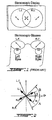
- Figure 1 illustrates such a system, where L.I . is a left image intended to be seen by the left eye only, R.I . is a right image intended to be seen by the right eye only, L.F . is a polarized left filter, which lets only the left image go through, and R.F . is a polarized right filter, which lets only the right image go through.
- TFT Thin Film Transistor
- TN Twist Nematic
- IPS In-Plane Switching
- MVA Multi-domain Vertical Alignment
- a LCD display consists essentially of two sheets of glass separated by a sealed-in liquid crystal material, which is normally transparent. A voltage applied between front and back electrode coatings disrupts an orderly arrangement of the liquid crystal molecules, darkening the liquid enough to form visible characters.
- a deep 3D perception is achieved by showing two images from a different point of view corresponding to each eye of the viewer, as in stereoscopy, with a unique advantage of displaying the two images without multiplexing them in time nor in space as is usually the case in most others stereoscopic technologies.
- the method consists in adjusting, for each picture element individually, the intensity of light as a function of the intensity value of two corresponding pixels in the left and right images, and polarizing, for each picture element individually, at an angle depending on the value of the two corresponding pixels of the left and right images.
- the resulting display is similar to any conventional LCD monitor but it comprises two LCD panels.
- the display comprises a series of layers, comprising, from back to front, a back light panel, a first polarized filter, a first LCD panel (Mod LCD), a second polarized filter and a second LCD panel (Ang LCD).
- the first LCD panel controls the pixel intensity for both eyes while the second LCD panel controls the distribution to one eye or the other.
- the device is based on two controllable LCD panels, which are connected to each other, the first panel behind the second panel. By the first panel the light intensity is controlled, the second panel controls the distribution of light intensity in two orthogonal polarization directions.
- US 6,570,629 B1 discloses an active matrix domain which is Integrated and disposed on one and the same substrate. Directions of orientation are differentiated by 90 DEG between one active matrix domain and the other active matrix domain. As a result, two images whose polarizing directions differ by 90 DEG are formed and can be seen as a stereoscopic image if the spectator wears eyeglasses with the appropriate respective polarization angle filter for each eye.
- a polarized display as defined in claim 1 and a method as defined in claim 27
- Figure 1 labeled "Prior Art”, is a diagram of a conventional stereoscopic display system
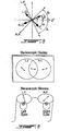
- Figure 2 is a graphic representation of a non-orthogonal polarized stereoscopic display according to an embodiment of a first aspect of the present invention
- Figure 3 Is a diagram of the non-orthogonal polarized stereoscopic display of Figure 2 ;
- Figure 4 is a diagram of conversion from an orthogonal system into an oblique system
- Figure 5 is a graphic representation of the non-orthogonal polarized stereoscopic display of Figure 2 In polar coordinates;
- Figure 6 Is a diagram of the non-orthogonal polarized
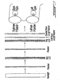
- Figure 7 illustrates a system with a half-wavelength retarder and a quarter-wavelength retarder sheet in the front of the display according to an embodiment of the present invention
- Figure 8 illustrates effects of the orientation of an optical axis of the retarder sheet of Figure 7 ;
- Figure 9 illustrates alternatives of the system of Figure 7 and 8 ;
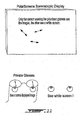
- Figure 10 illustrates an application of the systems of Figures 7 to 9 ;
- Figure 11 illustrates an application the systems of Figures 7 to 10 for two players in a game
- Figure 12 shows a portion of a left-right discrete matrix (fine line) and a Modulo-Angular (dotted line) discrete matrix
- FIG. 13 illustrates effects of overdriving an LCD
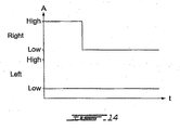
- Figure 14 illustrates cross-talk effects between right and left eyes
- Figures 15 illustrate effects of delaying an angular signal
- Figures 16 show a corresponding response of the LCD pixel in the case of Figure 15 .
- Figures 17 show a resulting pixel intensity at the eye of the viewer, after the left and right polarized filter, in the case of Figure 15 ;
- Figure 18 is an example of a LCD display using a front diffuser and incident back light, according to an embodiment of the present invention.
- Figure 19 is an example of a LCD display using micro-lens arrays to collimate light within every color sub-pixel, according to an embodiment of the present invention.
- Figures 20 show lens arrays matching the pixel pitch for a 1280 x 1024 LCD
- Figure 21 illustrates lens arrays matching the LCD pixel pitch
- Figure 22 illustrates a display according to a further embodiment of the present invention.
- Figure 23 illustrates a display using micro-ball array with black mask may be further used to diffuse the light without de-polarizing the light according to a further embodiment of the present invention
- Figure 24 illustrates a display using a micro-prism according to a further embodiment of the present invention.
- Figure 25 illustrates a display using micro-lens arrays according to an embodiment of an aspect of the present invention
- Figure 26 illustrates a display using Holographic Optical Elements sheets according to an embodiment of an aspect of the present invention.
- Figure 27 illustrates a display using an integrated LCD according to a further embodiment of the present invention.
- a polarized stereoscopic system comprising two polarized filters and generating two polarized images, wherein, contrary to conventional stereoscopic systems ( Figure 1 ), i) the two polarized filters are not necessary located at 90°, ii) the angle of a polarized image is not the same as a corresponding polarized filter i.e. the left filter is not at the left image angle and the right image is not at the same angle than the right filter, and iii) the system of angles is selected is such a way to cancel stereoscopic cross-talk, i.e. leakage from the right image to the left image and vice versa.
- the intensity of the left image L.I. after passing through the left filter L.F. is attenuated by a factor of cosine of the angle between the left filter L.F. and the left image L.I., i.e. cos (A - ⁇ ), while the intensity of the left image L.I. after passing through the right filter R.F. is null since the angle ( ⁇ + B) equals 90° by design and cos (90°) equals zero.
- the intensity of the right image R.I. after passing through the right filter R.F. is attenuated by a factor of cosine of the angle between the right filter R.F. and the right image R.I., i.e. cos (B - ⁇ )
- the intensity of the right image R.I. after passing through the left filter L.F. is null since the angle ( ⁇ + A) equals 90° by design and cos (90°) equals zero.
- a pixel is subdivided in three sub-pixels controlling the red, green and blue intensities of the pixel respectively, and each corresponding sub-pixels of the left and the right is converted into modular and angular values used to drive the first and the second LCDs of the polar stereoscopic display respectively, following relations (1) and (2) given hereinabove, where left is a value of the sub-pixel of the left image corresponding to a same sub-pixel on the right image, and right is a value of a sub-pixel of the right image corresponding to a same sub-pixel on the left image.
- L.O. is a left orientation of a sub-pixel angle value, when the right sub-pixel value is zero or negligible compared to the corresponding left sub-pixel value. It is a minimum generated angular value.
- R.O. is a right orientation of a sub-pixel angle value, when the left sub-pixel value is zero or negligible compared to the corresponding right sub-pixel value. It is a generated angular maximum value.
- Figure 6 shows the resulting non-orthogonal polarized polar stereoscopic display system.
- a conventional circular polarized stereoscopic display system uses left-handed and right-handed circular polarized filters to separate the left and the right images.
- the transformation from a linear polarized system to a circular polarized system and vice versa is performed by means of quarter-wavelength retarder films, wherein a fast axis of a retarder film placed at mid angle between the left and the right linear polarized angle transforms the linear polarized light into circular polarization light.
- the linear polarization is thus transformed into an elliptical polarization light by using appropriate elliptical polarized filters instead of the circular polarized filter.
- the present invention accommodates the low angular range of available commercial LCD panels. Indeed few of these commercial AM-LCD panels turn the light with a range of at least 90°, ranges varying, depending on the technologies such as TN, IPS or MVA, on manufacturers, and on LCD channel amplifier bias, between as low as 65° up to 85°. Moreover, these ranges vary between each primary color: for example, one tested panel may have the red varying from 45° to -25° while the blue varies from 45° to -40°.
- the non-orthogonal polarized stereoscopic system of the present invention may be adapted for each color, based on the same common polarized glasses.
- this aspect of the present invention allows a zero cross talk in a polar stereoscopic display system, as well as a faster switch in a CRT-LC panel stereoscopic display system, and a capacity to overdrive LCD at the extremes ends of angle swing for faster response. Moreover, it allows displaying two independent images polarized at an angle other than 90°.
- FIG. 7 By introducing a half-wavelength retarder and a quarter-wavelength retarder sheet in the front of the display as illustrated in Figure 7 , there is provided an elliptical polarized stereoscopic display system.
- Figure 8 shows how the orientation of the optical axis of the retarder sheet affects the paradigm of the polarization stereoscopic.
- the half-wavelength retarder sheet may modify the orientation range of the linear polarization portion of the light resulting in even more permutation of linear and circular polarization system.
- retarder sheets may increase the number of permutation in the non-orthogonal stereoscopic display system.
- Some of these permutations allow the selection of stereoscopic glasses where the left and the right elliptical polarized filters have the same amount of light going therethrough when the glasses are placed in front of each other, in such a way that a first person wearing the glasses may look comfortably at a second person wearing similar glasses.
- permutations of filter allow a people wearing them to look comfortably at another LCD monitor.
- this aspect of the present invention reduces the discomfort typically encountered in others stereoscopic polarized glasses, when looking at regular LCD monitor, wherein one eye sees the image on the monitor but the other eyes see black image, and when looking at another person wearing similar glasses, wherein one eye sees only a first eye of the first person and the other eye sees the second eye of the first person, which results very confusing for the brain.
- the present invention provides lock-up tables for rectangular to polar conversion system, for conversion of a live video, described hereinbelow in details, which allows resolving high processing power required to transform left and right images in Modulo and Angular images in real time, and also allows reducing cross-talk by individual combined values (left and right color values).
- the left and right images are converted to modular and angular values, for every sub-pixel as shown in the following diagram:
- the pixel light intensity of a regular LCD monitor has a linear response, with or without gamma correction, to a voltage or a value of the signal input.
- a Gamma correction is introduced to the Modulo feed in order to obtain a linear LCD pixel M'
- a Sinus transformation is used to compensate the LCD light intensity linear response so that the Angular signal generates a linear angular response A', as follows:
- Adjustment may be further introduced to compensate for a non-perfect response of LCD panel due to polarized filter and electronic, as follows:
- This processing of the signals may be integrated and stored in a memory used as a Lock-up table, as follows:
- LUT Lock-Up Tables
- the LUT may be implemented in SRAM (static random access memory), as exemplified below:
- the LUT (Lock-Up Table) is a unique and cost effective tool for achieving a sub-pixel frequency of a 1280 x 1024 at 85 Hz refresh rate, which requires a transformation processing clocked at 480 MHz. Moreover, the LUT makes it easier to introduce any desired adjustment.
- the present invention further allows enhanced contrast and color resolution, whereby the quality of a polar display in normal mode (2D) of may surpass currently available LCD displays by using the front LCD as a second light valve and controlling both LCD's in conjuncture in order to increase a number of available intensity levels. It is also possible to obtain blacker black pixel intensity by blocking more light using both LCD's.
- This feature allows private displays, characterized in that, by showing the image on the second LCD while displaying a complete white image on the first LCD, only the person wearing the polarized glasses (same as for enhanced contrast) is able to see the screen, while other people only see a white screen ( Figure 10 ).
- the private image to be shown on the second LCD is processed to remove the first image for the person wearing the polarized glasses.
- the image on the first LCD is selected or transformed to have enough brightness at every pixel so that each pixel of the second LCD has sufficient light to display the private image.
- each player may thus see different images on the same display.
- the first player wears glasses with both eyes at a first polarized orientation and the second player wear glasses at a second polarized orientation.
- the two orientations may be orthogonal or non-orthogonal as discussed earlier hereinabove ( Figure 11 ).
- the same display may switch, at the push of a button for example, between a normal 2D screen, a stereoscopic screen (by wearing passive 3D glasses), an enhanced 2D screen (by adding a film on the display surface), a security display screen (where only the person wearing special glasses see the image), and a two players- two displays- single screen-full screens display screen.
- Another problem may be solved in the present invention, such as cross talk, which may be reduced by using 2D matrix average of alternative display field.
- digitalization for converting the signal to discrete levels, for example 256 levels
- quantization errors which in turn may cause cross talk.
- Cartesian to polar conversion does not generate errors
- errors may still be caused by rounding of the modular and angular values, which in turn may creates a difference between the original left and right values and the display intensities.
- Figure 12 shows a portion of a left-right discrete matrix fine line) and a Modulo-Angular (dotted line) discrete matrix.
- the closest modular and angular discrete values are used to represent the left and right values but, as shown on the diagram, for some values combinations, the error may be quite large and may result in quantization errors and cross-talk. To minimize such error, it is contemplated to toggle at every video frame, or at a different rate but fast enough to prevent any flicker perceived by the viewer, between two Modulo-Angular discrete values in order to so obtain an average, which is closer to the left-right values (full line).
- Cross talk may be further reduced for fast moving images using LCD overdrive technique and using pre-angular adjustment, as will now be described.
- Overdriving a signal to a LCD during a short period of time accelerates a change of orientation of the LC crystals and yields a final value faster ( Figure 13 ).
- This system may work as well with high to low pixel value changes.
- overdriving may be limited at the extreme value of pixel intensity, i.e. zero and 255 for an 8-bit/color pixel, due to the lack of room to drive a higher or lower value.
- the present non-orthogonal stereoscopic display allows adding room for overdriving by reducing the angular range, thereby allowing an angular LCD of the display response faster at all values, which results in cross-talk reduction.
- Using a LCD overdrive as described hereinabove allows reducing crosstalk caused by the intermediary angle when the angle changes from one frame to the following frame, and reducing fast moving image smearing.
- the intensity change in a first eye may cause spurious light in the second eye, for example when a pixel of the right eye image changes from bright to dark while the corresponding pixel of the left eye image is dark ( Figure 14 ).
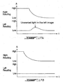
- FIG. 15 shows a normal system and the bottom one shows a system where the angular signal has been delayed, by one the time of one video frame for example.
- the corresponding response of the LCD pixel is shown in Figures 16 .
- the resulting pixel intensity at the eye of the viewer, after the left and right polarized filter is shown in Figures 17 .
- the overdrive technique may also be used to advance a signal instead of delaying it.
- the overdrive and delay techniques may be used together.
- the present invention allows solving the interference problem of stacked LCD panels and improving contrast at wide view angle, by allowing the collimation of light using one or more Micro-Lens Arrays layer placed before, in-between and/or after, the two LCD panels.
- the examples illustrated in Figures 18 and 19 allow very large viewing angle since the light goes through the pixels at a fixed angle, in contrast with standard LCD's in which the contrast reduces and the color shifts with the angle of view.
- Figure 18 illustrates an embodiment using a front diffuser and incident back light.
- Figure 19 illustrates an embodiment with micro-lens arrays to collimate light within every color sub-pixel.
- the pitch of the micro-lens arrays matches the LCD pixel pitch or sub-pixel pitch.
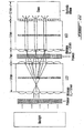
- Figures 20 show a lens arrays matching the pixel pitch for a 1280 x 1024 LCD.
- the light radiated from the backlight is focused through the pixel aperture of the first LCD and through the corresponding pixel aperture of the second LCD. Then the light coming out of the aperture of the second LCD may be diffused either by micro-lens or by a light diffuser layer or both.
- the micro-lens arrays may also be Gradians Index (GRIN) lenses type.
- GRIN Gradians Index
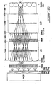
- the lens arrays matches the LCD pixel pitch as shown in Figure 21 .
- the color filter of the LCD panel may be used to create a parallel barrier and derivate the red and the blue light rays to the left adjacent and right adjacent pixels column of the angular LCD respectively.
- the electronics driving the LCD may be made to compensate for the shift by advancing the red and retarding the green channel by one pixel or vice versa if the LCD panel color matrix is BGR instead of RGB ( Figure 22 ).
- the fixed angle of light inside the display of the present invention allows the use of cholesteric color and polarized filters, which allows brightness gain of up to 600%, thereby compensating for the low brightness discussed hereinabove.
- Another method to increase the brightness of the display of the present invention makes use of a grating optical element for separating the color instead of filtering it, which, in combination with micro lens arrays, may yield an increase in brightness by 300%.
- a micro-ball array with black mask may be further used to diffuse the light without de-polarizing the light (as with the other type of diffuser), as illustrated in Figure 23 .
- a micro-prism may be added to deviate the red and blue light ray so they are perpendicular to plane as the green, as shown in Figure 24 .
- micro-lens arrays or GRINS lens arrays resolves the problem associated with the superposition of two pattern structures, such as the LCD cells, discussed hereinabove in relation to Figure 7 , by preventing the light ray at certain angle to go through the modulo LCD pixel adjacent the corresponding angular LCD pixel (at the same coordinate), which otherwise would result in parallax cross-talk between left and right images and a degradation of the image resolution. Therefore, brightness increased by allowing more light going through pixel aperture, and a very large viewing angle is obtained because the light goes through pixel at a fixed angle.
- Mini-lens arrays or GRINS lens arrays may further be used to perform the first and second LCD images replication ( Figure 25 ).
- One or more mini-Lens Arrays layers are placed in-between the two LCD of the stereoscopic display. These mini-lens arrays are selected to form a non-inverted 1:1 image projection, so that the light going through a sub-pixel of the first LCD goes through the corresponding sub-pixel of the second LCD.
- the pitch of the mini-lens arrays does not have to match the LCD pixel pitch.
- the mini-lens arrays may also be Gradians Index (GRIN) lenses type.
- GRIN Gradians Index
- a display using Holographic Optical Elements sheets to redirect the light to the corresponding pixels of the first LCD and the second LCD is shown in Figure 26 .
- Replication of the first and second LCD further resolves the problem associated with the superposition of two-pattern structure discussed above.
- the LCDs of the present invention may be integrated as illustrated in Figure 27 , wherein the two LCD panels are Integrated Into one LCD panel. Since then the modulo and the angular LCD structures are close together, the light from the backlight is directed through both corresponding pixels even at wide angles.
- a typical LCD panel is made of two glass substrates of a thickness typically around .7mm, a first glass substrate comprising the active part of the LCD and a glass substrate comprising the black matrix, the color filter and In certain case an ITO conductive layer acting as the anode or cathode.
- the liquid crystal is located in between these two substrates.
- two active .7mm substrates may be used, the first one controlled by the modular signal and the second one controlled by the angular signal.
- the two active substrates and the color filter are to be aligned.
- the second active substrate may have a black matrix layer.
Landscapes
- Engineering & Computer Science (AREA)
- Physics & Mathematics (AREA)
- Theoretical Computer Science (AREA)
- Computer Hardware Design (AREA)
- General Physics & Mathematics (AREA)
- Computer Security & Cryptography (AREA)
- Software Systems (AREA)
- General Engineering & Computer Science (AREA)
- Optics & Photonics (AREA)
- Multimedia (AREA)
- Signal Processing (AREA)
- Testing, Inspecting, Measuring Of Stereoscopic Televisions And Televisions (AREA)
- Liquid Crystal (AREA)
- Controls And Circuits For Display Device (AREA)
- Liquid Crystal Display Device Control (AREA)
- Control Of Indicators Other Than Cathode Ray Tubes (AREA)
Claims (27)
- Eine polarisierte Anzeige, die Folgendes umfasst:eine intensitätsmodulierende Matrixanzeige, wobei die intensitätsmodulierende Matrixanzeige eine vordere Oberfläche hat, undein polarisierendes Matrixanzeige-Panel vor der intensitätsmodulierenden Matrixanzeige, wobei das polarisierende Matrixanzeige-Panel eine vordere Oberfläche hat, wobei jeder Pixel der polarisierenden Matrixanzeige optisch mit einem entsprechendden Pixel der intensitätsmodulierenden Matrixanzeige arbeitet;wobei die polarisierte Anzeige eines von Folgendem ist:einer Linearpolarisations-Anzeige, wobei jeder Pixel des polarisierenden Matrixanzeige-Panels steuerbar ist und wobei eine Rotation eines erzeugten polarisierten Lichts über einen Bereich variiert, der 90 Grad und weniger einschließt, undeiner Anzeige für elliptische Polarisation, wobei jeder Pixel des polarisierenden Matrixanzeige-Panels steuerbar ist und wobei eine Phase zwischen einer schnellen und einer langsamen Achse eines polarisierten Lichts von einem entsprechenden Pixel der intensitätsmodulierenden Matrixanzeige in einem Bereich kommt, der 180 Grad und weniger einschließt,wobei jeder Pixel in Subpixel unterteilt ist, die eine rote, eine grüne und eine blaue Intensität steuern, wobei die intensitätsmodulierende Matrixanzeige beziehungsweise das polarisierende Matrixanzeige-Panel ausgebildet sind, um jeden entsprechenden Subpixel in bestimmte Modulo- und Winkel-(Angular)-Signale umzuwandeln, bei 90 Grad Rotation zwischen den zwei Polarisationsfiltern, die verwendet werden, um die polarisierte Anzeige zu betrachten, in einem kartesischen Winkelsystem wie folgt:worin left ein Wert eines Subpixels eines ersten Bildes ist, mit einem ersten linearen Polarisationswinkel, der einem gleichen Subpixel in einem zweiten Bild mit dem zweiten linearen Polarisationswinkel entspricht, und worin right ein Wert eines Subpixels des zweiten Bildes ist, der einem selben Subpixel im ersten Bild entspricht, wobei die Modulations-Anzeigematrix angeordnet ist, um jeden Subpixel entsprechend dem Modulo-Signal anzusteuern, und wobei das polarisierende Matrix-Panel angeordnet ist, um jeden Subpixel entsprechend dem Winkel-(Angular)-Signal anzusteuern,

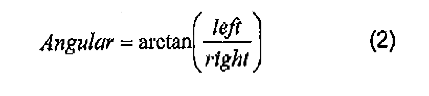
wobei die polarisierte Anzeige dadurch gekennzeichnet ist, dass
die Modulo- und Winkel-(Angular)-Signale, bei weniger als 90 Grad Rotation zwischen den zwei polarisierenden Filtern, die verwendet werden, um die polarisierte Anzeige zu betrachten, in einem schiefen Winkelsystem ω = α + β durch transformierte Modulo- und Winkel-Angulo-Signale gegeben werden wie folgt:

worin 2θ = (90° - (α + β)), L ein Wert eines Subpixels eines ersten Bildes ist, mit einem erster linearen Polarisationswinkel β, der einem gleichen Subpixel in einem zweiten Bild mit einem zweiten linearen Polarisationswinkel α entspricht, und wobei R ein Wert eines Subpixels des zweiten Bildes ist, der einem selben Subpixel im ersten Bild entspricht, wobei die Modulations-Anzeigematrix angeordnet ist, um jeden Subpixel entsprechend dem Modulo-Signal anzusteuern, und wobei das polarisierende Matrix-Panel angeordnet ist, um jeden Subpixel entsprechend dem Winkel-(Angular)-Signal anzusteuern. - Die Anzeige gemäß Anspruch 1, wobei die modulierende Matrixanzeige ein hintergrundbeleuchtetes Panel, einen ersten Polarisator, ein erstes Matrixanzeige-Panel und einen zweiten Polarisator umfasst, wobei das polarisierende Matrixanzeige-Panel ein zweites Matrixanzeige-Panel umfasst.
- Die Anzeige gemäß einem beliebigen der Ansprüche 1 und 2, wobei das polarisierende Matrixanzeige-Panel einen vorderen Halbwellenlängen-Verzögerungsglied umfasst.
- Die Anzeige gemäß Anspruch 3, wobei das polarisierende Matrixanzeige-Panel eine Viertelwellenlängen-Verzögerungsglied-Folie vor dem vorderen Halbwellenlängen-Verzögerungsglied umfasst und die Anzeige eine Anzeige für elliptische Polarisation ist.
- Die Anzeige gemäß einem beliebigen der Ansprüche 1 bis 4, wobei die Anzeige zur Betrachtung mit passiven 3D-Brillen dient, wodurch sich ein Raumbild ergibt.
- Die Anzeige gemäß Anspruch 1, wobei die intensitätsmodulierende Matrixanzeige ein erstes LCD-Panel umfasst und das polarisierende Matrixanzeige-Panel ein zweites LCD-Panel umfasst, wodurch ein erster Spieler, der eine Brille trägt, mit beiden Augen in einer ersten polarisierten Ausrichtung, und ein zweiter Spieler, der eine Brille trägt, mit beiden Augen in einer zweiten polarisierten Ausrichtung, auf derselben Anzeige verschiedene Bilder sehen.
- Die Anzeige gemäß einem beliebigen der Ansprüche 1 bis 6, wobei die intensitätsmodulierende Matrixanzeige eine erste Mikrolinsen-Anordnungsschicht und/oder Gradienten-Index-(GRIN-)-Linsen umfasst und das polarisierende Matrixanzeige-Panel eine erste Mikrolinsen-Anordnungsschicht und/oder Gradienten-Index-(GRIN-)-Linsen umfasst.
- Die Anzeige gemäß einem beliebigen der Ansprüche 1 bis 7, wobei das polarisierende Matrixanzeige-Panel entweder einen vorderen Diffusor oder einen vorderen Mikrokügelchen-Diffusor umfasst.
- Die Anzeige gemäß Anspruch 8, wobei das polarisierende Matrixanzeige-Panel ein Mikroprisma zwischen der vorderen Oberfläche davon und dem vorderen Mikrokügelchen-Diffusor umfasst.
- Die Anzeige gemäß einem beliebigen der Ansprüche 1 bis 9, wobei die intensitätsmodulierende Matrixanzeige in der vorderen Oberfläche davon ein optisches Gitterelement umfasst.
- Die Anzeige gemäß einem beliebigen der Ansprüche 1 bis 10, die eine Bildreplikatorschicht zwischen der intensitätsmodulierenden Matrixanzeige und dem polarisierenden Matrixanzeige-Panel umfasst.
- Die Anzeige gemäß Anspruch 11, wobei die Bildreplikatorschicht mindestens eines von Folgendem umfasst: MiniLinsen-Anordnungsschicht, wobei die Anordnungen ausgewählt sind, um eine nicht umgekehrte 1:1-Bildprojektion zu bilden, und Gradienten-Index-(GRIN-)-Linsen.
- Die Anzeige gemäß Anspruch 11, wobei die Bildreplikatorschicht mindestens eine Vorrichtung für holographische optische Elemente umfasst.
- Die Anzeige gemäß einem beliebigen der Ansprüche 1 bis 13, wobei die intensätütsmodulierende Matrixanzeige und das polarisierende Matrixanzeige-Panel in ein Matrixanzeige-Panel integriert sind.
- Die Anzeige gemäß Anspruch 14, wobei das integrierte Matrixanzeige-Panel zwei aktive Glassubstrate umfasst,
eine dünne Folie von Flüssigkristallen zwischen den zwei Substraten, wobei die dünne Folie eine leitende Indiumzinnoxidschicht und einen Farbfilter umfasst, wobei die zwei aktiven Substrate und der Farbfilter ausgerichtet sind. - Die Anzeige gemäß Anspruch 15, wobei die beiden aktiven Substrate ungefähr 0,7 mm dick sind, die dünne Schicht ist weniger als 0,2 mm.
- Die Anzeige gemäß einem beliebigen der Ansprüche 1 bis 16, wobei die intensitätsmodulierende Matrixanzeige und das polarisierende Matrixanzeige-Panel LCD-Panele umfassen.
- Die Anzeige gemäß Anspruch 1, die weiter einen ersten und einen zweiten linearen polarisierten Filter umfasst, die sich nebeneinander auf einer Ebene befinden, welche allgemein parallel ist zur vorderen Oberfläche des polarisierenden Matrixanzeige-Panels, das davor angeordnet ist, wobei sich der lineare polarisierte Filter in einem Winkel A 90° vom ersten linearen Polarisationswinkel β befindet und wobei der zweite lineare polarisierte Filter sich in einem Winkel B 90° vom zweiten linearen Polarisationswinkel α befindet, wobei die left und right Werte aus den transformierten modularen und Winkel-(Angular)-Signalen zurückgewonnen werden, mit den ersten und zweiten Filtern in A und B Winkeln wie folgt:


worin
- Die Anzeige gemäß einem beliebigen der Ansprüche 1 bis 18, die weiter ein Speichermittel zum Speichern transformierter Signale umfasst.
- Die Anzeige gemäß einem beliebigen der Ansprüche 1 bis 18, wobei jeder Rahmen zwischen zwei diskreten Modulo-Winkel-(Angular)-Signalen hin- und hergeschaltet wird, zur Erzielung eines Durchschnitts davon, wodurch das Nebensprechen zwischen dem ersten und dem zweiten Bild reduziert wird.
- Die Anzeige gemäß Anspruch 2, die weiter Mittel umfasst, um von einer Steuerung eine Übersteuerungs-Steuerung des ersten Matrixanzeige-Panels und/oder des zweiten Matrixanzeige-Panels zu empfangen.
- Die Anzeige gemäß einem beliebigen der Ansprüche 1 bis 20, die weiter Mittel umfasst, um von einer Steuerung eine Verzögerungssteuerung der modularen und Winkel-(Angular)-Signale zu empfangen, wodurch:i) wenn ein Subpixel von dunkel zu hell wechselt, während ein zweiter entsprechender Pixel dunkel ist, das Modulo-Signal relativ zu dem Winkel-(Angular)-signal verzögert wird, undii) wenn der erste Subpixel von hell zu dunkel wechselt, während der zweite entsprechende Pixel dunkel ist, das Winkel-(Angular)-signal relativ zum Modulo-Signal verzögert wird.
- Die Anzeige gemäß Anspruch 1, wobei die intensitätsmodulierende Matrixanzeige ein erstes LCD-Panel umfasst und das polarisierende Matrixanzeige-Panel ein zweites LCD-Panel umfasst, wobei das polarisierende Matrixanzeige-Panel eine Filterschicht an der vorderen Oberfläche davon umfasst, was einen verbesserten 2D-Bildschirm ergibt.
- Die Anzeige gemäß Anspruch 1, wobei das intensitätsmodulierende Matrixanzeige eine erstes LCD-Panel umfasst und das polarisierende Matrixanzeige-Panel ein zweites LCD-Panel umfasst, wobei die Anzeige der Betrachtung mit einem Nicht-3D-Typ einer polarisierten Brille dient, wodurch sich ein verbessertes 2D-Bild ergibt.
- Die Anzeige gemäß Anspruch 1, wobei die intensitätsmodulierende Matrixanzeige ein erstes LCD-Panel umfasst und das polarisierende Matrixanzeige-Panel ein zweites LCD-Panel umfasst, wodurch ein privates Bild, das auf der zweiten LCD gezeigt wird, mit einer polarisierten Brille zu sehen ist, während ein vollständiges weißes Bild, das auf der ersten LCD gezeigt wird, ohne polarisierte Brille sichtbar ist.
- Die Anzeige gemäß Anspruch 1, wobei die intensitätsmodulierende Matrixanzeige ein erstes LCD-Panel umfasst und das polarisierende Matrixanzeige-Panel ein zweites LCD-Panel umfasst, wodurch ein privates Bild, das auf der zweiten LCD gezeigt wird, mit einer polarisierten Brille zu sehen ist, während ein falsches Bild, das auf der ersten LCD gezeigt wird, ohne polarisierte Brille sichtbar ist.
- Ein Verfahren zur Erzeugung von Raumbildern, das folgende Schritte umfasst:Bereitstellung einer intensitätsmodulierenden Matrixanzeige,Bereitstellung eines polarisierenden Matrixanzeige-Panels nach der intensitätsmodulierenden Matrixanzeige, undentweder:a) Steuerung jedes Pixels des polarisierenden Matrixanzeige-Panels und einer Drehung eines erzeugten polarisierten Lichts über einen Bereich, der 90 Grad und weniger einschließt, oderb) Steuerung jedes Pixels des polarisierenden Matrixanzeige-Panels und einer Phase zwischen einer schnellen und einer langsamen Achse eines polarisierten Lichts, das von einem entsprechenden Pixel der intensitätsmodulierenden Matrixanzeige kommt, über einen Bereich, der 180 Grad und weniger einschließt,wobei jeder Pixel in Subpixel unterteilt ist, die eine rote, eine grüne und eine blaue Intensität steuern, wobei die intensitätsmodulierende Matrixanzeige bzw. das polarisierende Matrixanzeige-Panel ausgebildet sind, um jeden entsprechenden Subpixel in bestimmte Modulo- und Winkel-(Angular)-Signale umzuwandeln, bei 90 Grad Rotation zwischen den zwei polarisierenden Filtern, die verwendet werden, um die polarisierte Anzeige zu betrachten, in einem kartesischen Winkelsystem wie folgt:


worin left ein Wert eines Subpixels eines ersten Bildes ist, mit einem ersten linearen Polarisationswinkel, der einem gleichen Subpixel in einem zweiten Bild mit dem zweiten linearen Polarisationswinkel entspricht, und wobei right ein Wert eines Subpixels des zweiten Bildes ist, der einem selben Subpixel im ersten Bild entspricht, wobei die Modulations-Anzeigematrix angeordnet ist, um jeden Subpixel entsprechend dem Modulo-Signal anzusteuern, und wobei das polarisierende Matrixan-Panel angeordnet ist, um jeden Subpixel entsprechend dem Winkel-(Angular)-Signal anzusteuern,
wobei die Modulo- und Winkel-(Angular)-Signale bei weniger als 90 Grad Rotation zwischen den zwei polarisierenden Filtern, die verwendet werden, um die polarisierte Anzeige zu betrachten, in einem schiefen Winkelsystem ω = α + β durch transformierte Modulo- und Winkel-(Angular)-Signale gegeben werden, und zwar wie folgt:

worin 2θ = (90° - (α + β)), L ein Wert eines Subpixels eines ersten Bildes ist, mit einem ersten linearen Polarisationswinkel β, der einem gleichen Subpixel in einem zweiten Bild entspricht, mit einem zweiten Linearpolarisationswinkel α und R ein Wert eines Subpixels des zweiten Bildes ist, der einem selben Subpixel im ersten Bild entspricht, wobei die Modulations-Anzeigematrix angeordnet ist, um jeden Subpixel entsprechend dem Modulo-Signal anzusteuern, und das polarisierende Matrix-Panel angeordnet ist, um jeden Subpixel entsprechend dem Winkel-(Angulo)-Signal anzusteuern.
Applications Claiming Priority (2)
| Application Number | Priority Date | Filing Date | Title |
|---|---|---|---|
| US53701604P | 2004-01-20 | 2004-01-20 | |
| PCT/CA2005/000065 WO2005069269A1 (en) | 2004-01-20 | 2005-01-20 | Stereoscopic display system |
Publications (3)
| Publication Number | Publication Date |
|---|---|
| EP1709623A1 EP1709623A1 (de) | 2006-10-11 |
| EP1709623A4 EP1709623A4 (de) | 2010-11-03 |
| EP1709623B1 true EP1709623B1 (de) | 2012-07-11 |
Family
ID=34794435
Family Applications (1)
| Application Number | Title | Priority Date | Filing Date |
|---|---|---|---|
| EP05726212A Expired - Lifetime EP1709623B1 (de) | 2004-01-20 | 2005-01-20 | Stereo-anzeigesystem |
Country Status (6)
| Country | Link |
|---|---|
| US (1) | US7705935B2 (de) |
| EP (1) | EP1709623B1 (de) |
| JP (1) | JP2007519042A (de) |
| KR (1) | KR101135757B1 (de) |
| CN (1) | CN1930605B (de) |
| WO (1) | WO2005069269A1 (de) |
Families Citing this family (55)
| Publication number | Priority date | Publication date | Assignee | Title |
|---|---|---|---|---|
| JP2008523421A (ja) * | 2004-12-06 | 2008-07-03 | コーニンクレッカ フィリップス エレクトロニクス エヌ ヴィ | 立体表示機器 |
| JP2009507248A (ja) * | 2005-07-11 | 2009-02-19 | ニューロック オプティックス エルエルシー | 3次元撮像に適した円偏光および偏光眼鏡を用いた2パネル液晶システム |
| WO2007040127A1 (ja) * | 2005-09-30 | 2007-04-12 | Sharp Kabushiki Kaisha | 液晶表示装置およびテレビジョン受信機 |
| JP5508721B2 (ja) * | 2006-02-10 | 2014-06-04 | リアルディー インコーポレイテッド | 多機能アクティブマトリクス型液晶ディスプレイ |
| CN101467199B (zh) * | 2006-08-02 | 2011-08-31 | 夏普株式会社 | 液晶显示装置、液晶显示方法以及电视接收机 |
| KR100852758B1 (ko) | 2006-09-14 | 2008-08-18 | 한국과학기술연구원 | 영상 디스플레이 장치 |
| BRPI0718820A2 (pt) * | 2006-11-06 | 2014-09-16 | Master Image Co Ltd | Sistema de projeção de imagem estereoscópica utilizando módulo de filtro de polarização circular |
| GB0709411D0 (en) * | 2007-05-16 | 2007-06-27 | Barco Nv | Methods and systems for stereoscopic imaging |
| US9088792B2 (en) * | 2007-06-08 | 2015-07-21 | Reald Inc. | Stereoscopic flat panel display with synchronized backlight, polarization control panel, and liquid crystal display |
| US8506085B2 (en) | 2007-08-28 | 2013-08-13 | Dell Products, L.P. | Methods and systems for projecting images |
| US8115698B2 (en) * | 2007-08-28 | 2012-02-14 | Dell Products, L.P. | Methods and systems for image processing and display |
| US8462949B2 (en) * | 2007-11-29 | 2013-06-11 | Oculis Labs, Inc. | Method and apparatus for secure display of visual content |
| GB2457692A (en) * | 2008-02-21 | 2009-08-26 | Sharp Kk | A display device with a plurality of viewing modes |
| TW201011414A (en) * | 2008-09-12 | 2010-03-16 | Chunghwa Picture Tubes Ltd | Three-dimensional display device |
| JP5321009B2 (ja) * | 2008-11-21 | 2013-10-23 | ソニー株式会社 | 画像信号処理装置、画像信号処理方法および画像投射装置 |
| US8587639B2 (en) * | 2008-12-11 | 2013-11-19 | Alcatel Lucent | Method of improved three dimensional display technique |
| US8581969B2 (en) * | 2008-12-11 | 2013-11-12 | Nvidia Corporation | Single display system and method for displaying stereoscopic content |
| JP5603042B2 (ja) * | 2009-09-14 | 2014-10-08 | 株式会社有沢製作所 | 立体画像表示装置 |
| TWI419144B (zh) * | 2009-10-08 | 2013-12-11 | Acer Inc | Display brightness control method and display device thereof |
| KR101040701B1 (ko) * | 2009-12-22 | 2011-06-13 | 주식회사 엘지화학 | 입체영상표시장치용 3d입체안경 및 이를 포함하는 입체영상표시장치 |
| TWI417866B (zh) * | 2010-04-22 | 2013-12-01 | Chunghwa Picture Tubes Ltd | 立體畫面顯示方法及其立體顯示裝置 |
| KR101303456B1 (ko) * | 2010-06-22 | 2013-09-10 | 엘지디스플레이 주식회사 | 3차원 데이터 변조방법과 이를 이용한 액정표시장치 |
| TWI387315B (zh) * | 2010-06-29 | 2013-02-21 | Acer Inc | 用來觀看立體影像之快門眼鏡 |
| RU2013110750A (ru) * | 2010-08-12 | 2014-09-20 | 3Д Диджитал, Ллк | Устройство, способ и изделие для создания трехмерного эффекта с использованием активных очков |
| TW201209479A (en) * | 2010-08-18 | 2012-03-01 | Chunghwa Picture Tubes Ltd | 3D image display device and signal controlling method therefor |
| JP2012053165A (ja) * | 2010-08-31 | 2012-03-15 | Sony Corp | 情報処理装置、プログラムおよび情報処理方法 |
| KR20120035825A (ko) * | 2010-10-06 | 2012-04-16 | 삼성전자주식회사 | 3d 디스플레이 패널 및 이를 이용하는 3d 디스플레이 장치와 그 구동 방법 |
| JP5631235B2 (ja) * | 2011-02-18 | 2014-11-26 | 三菱電機株式会社 | 透過光選択装置、立体画像表示装置及び立体画像表示方法 |
| WO2012139108A1 (en) | 2011-04-08 | 2012-10-11 | Dolby Laboratories Licensing Corporation | Method and apparatus for flicker reduction and contrast enhancement in 3d displays |
| US20120299805A1 (en) * | 2011-05-26 | 2012-11-29 | Sanyo Electric., Ltd. | Projection display apparatus |
| US8941801B2 (en) * | 2011-06-14 | 2015-01-27 | Reald Inc. | In-plane switched active retarder for stereoscopic display systems |
| CN102419494B (zh) * | 2011-06-21 | 2014-07-16 | 深圳市华星光电技术有限公司 | 显示面板及其应用的显示装置 |
| TW201306562A (zh) * | 2011-07-19 | 2013-02-01 | Acer Inc | 用於改善三維顯示品質的方法 |
| WO2013013230A2 (en) * | 2011-07-21 | 2013-01-24 | Jonathan Arnold Bell | Wearable display devices |
| CN102917229A (zh) * | 2011-08-03 | 2013-02-06 | 宏碁股份有限公司 | 用于改善三维显示品质的方法 |
| TWI449956B (zh) * | 2011-08-23 | 2014-08-21 | Acer Inc | 主動式偏光三維顯示裝置 |
| CN102981283B (zh) * | 2011-09-07 | 2015-04-08 | 宏碁股份有限公司 | 主动式偏光三维显示装置 |
| US9414049B2 (en) | 2011-09-19 | 2016-08-09 | Écrans Polaires Inc./Polar Screens Inc. | Method and display for showing a stereoscopic image |
| KR20130039066A (ko) * | 2011-10-11 | 2013-04-19 | 삼성디스플레이 주식회사 | 표시 장치, 이를 포함하는 표시 시스템 및 표시 장치의 제조 방법 |
| KR101299184B1 (ko) * | 2012-02-28 | 2013-08-21 | 엘지디스플레이 주식회사 | 3차원 영상 구현 시스템 |
| KR20130125664A (ko) * | 2012-05-09 | 2013-11-19 | 삼성전자주식회사 | 디스플레이 패널 및 이를 구비하는 디스플레이 장치 |
| CN103235441B (zh) * | 2013-04-22 | 2015-10-14 | 京东方科技集团股份有限公司 | 一种液晶显示装置、专用眼镜及显示器件 |
| KR102156408B1 (ko) * | 2013-11-19 | 2020-09-16 | 삼성전자주식회사 | 레이어드 디스플레이 기법을 위한 디스플레이 장치 및 영상 생성 방법 |
| JP6384092B2 (ja) * | 2014-04-01 | 2018-09-05 | セイコーエプソン株式会社 | 液晶装置及び電子機器 |
| KR102310106B1 (ko) | 2014-04-04 | 2021-10-08 | 삼성전자주식회사 | 서비스 화면을 표시하기 위한 전자 장치 및 방법 |
| US9176328B1 (en) | 2015-02-09 | 2015-11-03 | Nanografix Corporation | Generic optical matrices having pixels corresponding to color and sub-pixels corresponding to non-color effects, and associated methods |
| US9176473B1 (en) | 2015-02-09 | 2015-11-03 | Nanografix Corporation | Systems and methods for fabricating variable digital optical images using generic optical matrices |
| US9188954B1 (en) | 2015-02-09 | 2015-11-17 | Nanografix Corporation | Systems and methods for generating negatives of variable digital optical images based on desired images and generic optical matrices |
| US10831155B2 (en) | 2015-02-09 | 2020-11-10 | Nanografix Corporation | Systems and methods for fabricating variable digital optical images using generic optical matrices |
| CN106647212B (zh) * | 2015-11-03 | 2019-06-04 | 北京理工大学 | 一种全息三维显示方法及系统 |
| US20200169724A1 (en) * | 2017-08-16 | 2020-05-28 | NutriCern, Inc. | Optimizing perception of stereoscopic visual content |
| CN108051928A (zh) * | 2018-01-22 | 2018-05-18 | 成都工业学院 | 一种虚拟现实眼镜及3d显示系统 |
| US11449004B2 (en) | 2020-05-21 | 2022-09-20 | Looking Glass Factory, Inc. | System and method for holographic image display |
| WO2021262860A1 (en) | 2020-06-23 | 2021-12-30 | Looking Glass Factory, Inc. | System and method for holographic communication |
| WO2022119940A1 (en) | 2020-12-01 | 2022-06-09 | Looking Glass Factory, Inc. | System and method for processing three dimensional images |
Family Cites Families (16)
| Publication number | Priority date | Publication date | Assignee | Title |
|---|---|---|---|---|
| JPS6271394A (ja) * | 1985-09-25 | 1987-04-02 | Yazaki Corp | 立体映像表示装置 |
| JPS63182991A (ja) * | 1987-01-26 | 1988-07-28 | Hitachi Ltd | 立体テレビジヨン装置 |
| US5903388A (en) * | 1992-06-11 | 1999-05-11 | Sedlmayr Steven R | High efficiency electromagnetic beam projector and systems and method for implementation thereof |
| JPH06110076A (ja) * | 1992-09-25 | 1994-04-22 | Sony Corp | 液晶表示装置 |
| JPH10510400A (ja) * | 1994-12-09 | 1998-10-06 | ゴウドレアウ、ジーン−エティエン | 立体表示方法及び装置 |
| DE19510671A1 (de) * | 1995-03-27 | 1996-10-02 | Charalampos Avgoustinos | Vorrichtung zur 3-D Bilddarstellung |
| US5999240A (en) * | 1995-05-23 | 1999-12-07 | Colorlink, Inc. | Optical retarder stack pair for transforming input light into polarization states having saturated color spectra |
| US6570629B1 (en) * | 1995-10-14 | 2003-05-27 | Semiconductor Energy Laboratory Co., Ltd. | Display unit including first and second active matrix regions that is provided completely outside each other |
| CN1132136C (zh) * | 1995-12-22 | 2003-12-24 | 皇家菲利浦电子有限公司 | 带两个微透镜列阵的图象显示装置 |
| JP3631318B2 (ja) * | 1996-03-12 | 2005-03-23 | オリンパス株式会社 | 液晶表示装置及び頭部搭載型映像表示装置 |
| GB2317524A (en) * | 1996-09-19 | 1998-03-25 | Sharp Kk | Three dimensional stereoscopic projection display |
| EP0941616A1 (de) * | 1996-12-06 | 1999-09-15 | The Rowland Institute For Science | Elektronische stereoskopische anzeigevorrichtung |
| US6529250B1 (en) * | 1997-05-22 | 2003-03-04 | Seiko Epson Corporation | Projector |
| JP3822361B2 (ja) * | 1998-07-10 | 2006-09-20 | 株式会社日立製作所 | 配光制御素子およびこれを備えた表示装置 |
| CN2422659Y (zh) * | 2000-01-29 | 2001-03-07 | 杨克立 | 叠层液晶式三维图像显示屏 |
| GB0119176D0 (en) * | 2001-08-06 | 2001-09-26 | Ocuity Ltd | Optical switching apparatus |
-
2005
- 2005-01-20 WO PCT/CA2005/000065 patent/WO2005069269A1/en not_active Ceased
- 2005-01-20 CN CN2005800072808A patent/CN1930605B/zh not_active Expired - Fee Related
- 2005-01-20 KR KR1020067016666A patent/KR101135757B1/ko not_active Expired - Fee Related
- 2005-01-20 EP EP05726212A patent/EP1709623B1/de not_active Expired - Lifetime
- 2005-01-20 JP JP2006549807A patent/JP2007519042A/ja active Pending
- 2005-01-20 US US10/586,108 patent/US7705935B2/en not_active Expired - Fee Related
Also Published As
| Publication number | Publication date |
|---|---|
| US7705935B2 (en) | 2010-04-27 |
| CN1930605B (zh) | 2010-05-05 |
| KR20060134070A (ko) | 2006-12-27 |
| US20080246897A1 (en) | 2008-10-09 |
| EP1709623A1 (de) | 2006-10-11 |
| KR101135757B1 (ko) | 2012-04-24 |
| JP2007519042A (ja) | 2007-07-12 |
| CN1930605A (zh) | 2007-03-14 |
| EP1709623A4 (de) | 2010-11-03 |
| WO2005069269A1 (en) | 2005-07-28 |
Similar Documents
| Publication | Publication Date | Title |
|---|---|---|
| EP1709623B1 (de) | Stereo-anzeigesystem | |
| JP4944235B2 (ja) | 切り替え可能な複屈折レンズアレイ及びこれを備えた表示装置 | |
| US7400377B2 (en) | Display having particular polarisation modifying layer | |
| US8345088B2 (en) | Autostereoscopic display apparatus | |
| JP3452470B2 (ja) | ディスプレイ | |
| CN100397478C (zh) | 多视图显示器 | |
| JP5156606B2 (ja) | 立体画像表示装置 | |
| US9237337B2 (en) | Autostereoscopic display with a passive cycloidal diffractive waveplate | |
| JP4654183B2 (ja) | レンズアレイ構造 | |
| US7986283B2 (en) | Multi-dimensional image selectable display device | |
| US10216034B2 (en) | Liquid crystal display device | |
| WO2014018269A1 (en) | Observer tracking autostereoscopic display | |
| GB2296099A (en) | Spatial light modulator | |
| US20070296889A1 (en) | LCD-based confidential viewing apparatus utilizing auto-inversion masking | |
| US20130335646A1 (en) | Display panel of stereoscopic image display | |
| KR20150004028A (ko) | 입체 영상 표시장치 | |
| KR20080000497A (ko) | 광협시야각 모드 전환 가능한 영상표시장치 및 그 구동방법 | |
| KR100456068B1 (ko) | 입체 영상 액정 표시 장치 및 그것의 제조 방법 | |
| KR20130025761A (ko) | 편광안경방식 입체영상표시장치 |
Legal Events
| Date | Code | Title | Description |
|---|---|---|---|
| PUAI | Public reference made under article 153(3) epc to a published international application that has entered the european phase |
Free format text: ORIGINAL CODE: 0009012 |
|
| 17P | Request for examination filed |
Effective date: 20060804 |
|
| AK | Designated contracting states |
Kind code of ref document: A1 Designated state(s): AT BE BG CH CY CZ DE DK EE ES FI FR GB GR HU IE IS IT LI LT LU MC NL PL PT RO SE SI SK TR |
|
| DAX | Request for extension of the european patent (deleted) | ||
| A4 | Supplementary search report drawn up and despatched |
Effective date: 20101005 |
|
| 17Q | First examination report despatched |
Effective date: 20110315 |
|
| REG | Reference to a national code |
Ref country code: DE Ref legal event code: R079 Ref document number: 602005035115 Country of ref document: DE Free format text: PREVIOUS MAIN CLASS: G09G0005000000 Ipc: G02B0027260000 |
|
| RIC1 | Information provided on ipc code assigned before grant |
Ipc: G02B 27/26 20060101AFI20110906BHEP |
|
| GRAP | Despatch of communication of intention to grant a patent |
Free format text: ORIGINAL CODE: EPIDOSNIGR1 |
|
| RIN1 | Information on inventor provided before grant (corrected) |
Inventor name: GAUDREAU, JEAN-ETIENNE |
|
| GRAS | Grant fee paid |
Free format text: ORIGINAL CODE: EPIDOSNIGR3 |
|
| GRAA | (expected) grant |
Free format text: ORIGINAL CODE: 0009210 |
|
| AK | Designated contracting states |
Kind code of ref document: B1 Designated state(s): AT BE BG CH CY CZ DE DK EE ES FI FR GB GR HU IE IS IT LI LT LU MC NL PL PT RO SE SI SK TR |
|
| REG | Reference to a national code |
Ref country code: GB Ref legal event code: FG4D |
|
| REG | Reference to a national code |
Ref country code: CH Ref legal event code: EP |
|
| REG | Reference to a national code |
Ref country code: AT Ref legal event code: REF Ref document number: 566406 Country of ref document: AT Kind code of ref document: T Effective date: 20120715 |
|
| REG | Reference to a national code |
Ref country code: IE Ref legal event code: FG4D |
|
| REG | Reference to a national code |
Ref country code: DE Ref legal event code: R096 Ref document number: 602005035115 Country of ref document: DE Effective date: 20120906 |
|
| REG | Reference to a national code |
Ref country code: NL Ref legal event code: VDEP Effective date: 20120711 |
|
| REG | Reference to a national code |
Ref country code: AT Ref legal event code: MK05 Ref document number: 566406 Country of ref document: AT Kind code of ref document: T Effective date: 20120711 |
|
| REG | Reference to a national code |
Ref country code: LT Ref legal event code: MG4D Effective date: 20120711 |
|
| PG25 | Lapsed in a contracting state [announced via postgrant information from national office to epo] |
Ref country code: CY Free format text: LAPSE BECAUSE OF FAILURE TO SUBMIT A TRANSLATION OF THE DESCRIPTION OR TO PAY THE FEE WITHIN THE PRESCRIBED TIME-LIMIT Effective date: 20120711 Ref country code: LT Free format text: LAPSE BECAUSE OF FAILURE TO SUBMIT A TRANSLATION OF THE DESCRIPTION OR TO PAY THE FEE WITHIN THE PRESCRIBED TIME-LIMIT Effective date: 20120711 Ref country code: FI Free format text: LAPSE BECAUSE OF FAILURE TO SUBMIT A TRANSLATION OF THE DESCRIPTION OR TO PAY THE FEE WITHIN THE PRESCRIBED TIME-LIMIT Effective date: 20120711 Ref country code: BE Free format text: LAPSE BECAUSE OF FAILURE TO SUBMIT A TRANSLATION OF THE DESCRIPTION OR TO PAY THE FEE WITHIN THE PRESCRIBED TIME-LIMIT Effective date: 20120711 Ref country code: AT Free format text: LAPSE BECAUSE OF FAILURE TO SUBMIT A TRANSLATION OF THE DESCRIPTION OR TO PAY THE FEE WITHIN THE PRESCRIBED TIME-LIMIT Effective date: 20120711 Ref country code: IS Free format text: LAPSE BECAUSE OF FAILURE TO SUBMIT A TRANSLATION OF THE DESCRIPTION OR TO PAY THE FEE WITHIN THE PRESCRIBED TIME-LIMIT Effective date: 20121111 |
|
| PG25 | Lapsed in a contracting state [announced via postgrant information from national office to epo] |
Ref country code: PT Free format text: LAPSE BECAUSE OF FAILURE TO SUBMIT A TRANSLATION OF THE DESCRIPTION OR TO PAY THE FEE WITHIN THE PRESCRIBED TIME-LIMIT Effective date: 20121112 Ref country code: SI Free format text: LAPSE BECAUSE OF FAILURE TO SUBMIT A TRANSLATION OF THE DESCRIPTION OR TO PAY THE FEE WITHIN THE PRESCRIBED TIME-LIMIT Effective date: 20120711 Ref country code: GR Free format text: LAPSE BECAUSE OF FAILURE TO SUBMIT A TRANSLATION OF THE DESCRIPTION OR TO PAY THE FEE WITHIN THE PRESCRIBED TIME-LIMIT Effective date: 20121012 Ref country code: PL Free format text: LAPSE BECAUSE OF FAILURE TO SUBMIT A TRANSLATION OF THE DESCRIPTION OR TO PAY THE FEE WITHIN THE PRESCRIBED TIME-LIMIT Effective date: 20120711 Ref country code: SE Free format text: LAPSE BECAUSE OF FAILURE TO SUBMIT A TRANSLATION OF THE DESCRIPTION OR TO PAY THE FEE WITHIN THE PRESCRIBED TIME-LIMIT Effective date: 20120711 |
|
| PG25 | Lapsed in a contracting state [announced via postgrant information from national office to epo] |
Ref country code: NL Free format text: LAPSE BECAUSE OF FAILURE TO SUBMIT A TRANSLATION OF THE DESCRIPTION OR TO PAY THE FEE WITHIN THE PRESCRIBED TIME-LIMIT Effective date: 20120711 |
|
| PG25 | Lapsed in a contracting state [announced via postgrant information from national office to epo] |
Ref country code: ES Free format text: LAPSE BECAUSE OF FAILURE TO SUBMIT A TRANSLATION OF THE DESCRIPTION OR TO PAY THE FEE WITHIN THE PRESCRIBED TIME-LIMIT Effective date: 20121022 Ref country code: CZ Free format text: LAPSE BECAUSE OF FAILURE TO SUBMIT A TRANSLATION OF THE DESCRIPTION OR TO PAY THE FEE WITHIN THE PRESCRIBED TIME-LIMIT Effective date: 20120711 Ref country code: EE Free format text: LAPSE BECAUSE OF FAILURE TO SUBMIT A TRANSLATION OF THE DESCRIPTION OR TO PAY THE FEE WITHIN THE PRESCRIBED TIME-LIMIT Effective date: 20120711 Ref country code: DK Free format text: LAPSE BECAUSE OF FAILURE TO SUBMIT A TRANSLATION OF THE DESCRIPTION OR TO PAY THE FEE WITHIN THE PRESCRIBED TIME-LIMIT Effective date: 20120711 Ref country code: RO Free format text: LAPSE BECAUSE OF FAILURE TO SUBMIT A TRANSLATION OF THE DESCRIPTION OR TO PAY THE FEE WITHIN THE PRESCRIBED TIME-LIMIT Effective date: 20120711 |
|
| PLBE | No opposition filed within time limit |
Free format text: ORIGINAL CODE: 0009261 |
|
| STAA | Information on the status of an ep patent application or granted ep patent |
Free format text: STATUS: NO OPPOSITION FILED WITHIN TIME LIMIT |
|
| PG25 | Lapsed in a contracting state [announced via postgrant information from national office to epo] |
Ref country code: IT Free format text: LAPSE BECAUSE OF FAILURE TO SUBMIT A TRANSLATION OF THE DESCRIPTION OR TO PAY THE FEE WITHIN THE PRESCRIBED TIME-LIMIT Effective date: 20120711 Ref country code: SK Free format text: LAPSE BECAUSE OF FAILURE TO SUBMIT A TRANSLATION OF THE DESCRIPTION OR TO PAY THE FEE WITHIN THE PRESCRIBED TIME-LIMIT Effective date: 20120711 |
|
| 26N | No opposition filed |
Effective date: 20130412 |
|
| PG25 | Lapsed in a contracting state [announced via postgrant information from national office to epo] |
Ref country code: BG Free format text: LAPSE BECAUSE OF FAILURE TO SUBMIT A TRANSLATION OF THE DESCRIPTION OR TO PAY THE FEE WITHIN THE PRESCRIBED TIME-LIMIT Effective date: 20121011 |
|
| REG | Reference to a national code |
Ref country code: DE Ref legal event code: R097 Ref document number: 602005035115 Country of ref document: DE Effective date: 20130412 |
|
| PG25 | Lapsed in a contracting state [announced via postgrant information from national office to epo] |
Ref country code: MC Free format text: LAPSE BECAUSE OF NON-PAYMENT OF DUE FEES Effective date: 20130131 |
|
| REG | Reference to a national code |
Ref country code: CH Ref legal event code: PL |
|
| REG | Reference to a national code |
Ref country code: IE Ref legal event code: MM4A |
|
| PG25 | Lapsed in a contracting state [announced via postgrant information from national office to epo] |
Ref country code: CH Free format text: LAPSE BECAUSE OF NON-PAYMENT OF DUE FEES Effective date: 20130131 Ref country code: LI Free format text: LAPSE BECAUSE OF NON-PAYMENT OF DUE FEES Effective date: 20130131 |
|
| PG25 | Lapsed in a contracting state [announced via postgrant information from national office to epo] |
Ref country code: IE Free format text: LAPSE BECAUSE OF NON-PAYMENT OF DUE FEES Effective date: 20130120 |
|
| PGFP | Annual fee paid to national office [announced via postgrant information from national office to epo] |
Ref country code: DE Payment date: 20140131 Year of fee payment: 10 |
|
| PGFP | Annual fee paid to national office [announced via postgrant information from national office to epo] |
Ref country code: FR Payment date: 20140131 Year of fee payment: 10 |
|
| PGFP | Annual fee paid to national office [announced via postgrant information from national office to epo] |
Ref country code: GB Payment date: 20140117 Year of fee payment: 10 |
|
| PG25 | Lapsed in a contracting state [announced via postgrant information from national office to epo] |
Ref country code: TR Free format text: LAPSE BECAUSE OF FAILURE TO SUBMIT A TRANSLATION OF THE DESCRIPTION OR TO PAY THE FEE WITHIN THE PRESCRIBED TIME-LIMIT Effective date: 20120711 |
|
| PG25 | Lapsed in a contracting state [announced via postgrant information from national office to epo] |
Ref country code: LU Free format text: LAPSE BECAUSE OF NON-PAYMENT OF DUE FEES Effective date: 20130120 Ref country code: HU Free format text: LAPSE BECAUSE OF FAILURE TO SUBMIT A TRANSLATION OF THE DESCRIPTION OR TO PAY THE FEE WITHIN THE PRESCRIBED TIME-LIMIT; INVALID AB INITIO Effective date: 20050120 |
|
| REG | Reference to a national code |
Ref country code: DE Ref legal event code: R119 Ref document number: 602005035115 Country of ref document: DE |
|
| GBPC | Gb: european patent ceased through non-payment of renewal fee |
Effective date: 20150120 |
|
| PG25 | Lapsed in a contracting state [announced via postgrant information from national office to epo] |
Ref country code: DE Free format text: LAPSE BECAUSE OF NON-PAYMENT OF DUE FEES Effective date: 20150801 Ref country code: GB Free format text: LAPSE BECAUSE OF NON-PAYMENT OF DUE FEES Effective date: 20150120 |
|
| REG | Reference to a national code |
Ref country code: FR Ref legal event code: ST Effective date: 20150930 |
|
| PG25 | Lapsed in a contracting state [announced via postgrant information from national office to epo] |
Ref country code: FR Free format text: LAPSE BECAUSE OF NON-PAYMENT OF DUE FEES Effective date: 20150202 |