EP1709882A2 - Buckle for a belt - Google Patents
Buckle for a belt Download PDFInfo
- Publication number
- EP1709882A2 EP1709882A2 EP06425233A EP06425233A EP1709882A2 EP 1709882 A2 EP1709882 A2 EP 1709882A2 EP 06425233 A EP06425233 A EP 06425233A EP 06425233 A EP06425233 A EP 06425233A EP 1709882 A2 EP1709882 A2 EP 1709882A2
- Authority
- EP
- European Patent Office
- Prior art keywords
- plaque
- slot
- buckle
- belt
- mask
- Prior art date
- Legal status (The legal status is an assumption and is not a legal conclusion. Google has not performed a legal analysis and makes no representation as to the accuracy of the status listed.)
- Withdrawn
Links
- 238000000034 method Methods 0.000 claims description 9
- 230000009194 climbing Effects 0.000 description 3
- 241001503987 Clematis vitalba Species 0.000 description 1
- 230000001133 acceleration Effects 0.000 description 1
- 230000006978 adaptation Effects 0.000 description 1
- 230000001419 dependent effect Effects 0.000 description 1
- 238000012986 modification Methods 0.000 description 1
- 230000004048 modification Effects 0.000 description 1
Images


Classifications
-
- A—HUMAN NECESSITIES
- A44—HABERDASHERY; JEWELLERY
- A44B—BUTTONS, PINS, BUCKLES, SLIDE FASTENERS, OR THE LIKE
- A44B11/00—Buckles; Similar fasteners for interconnecting straps or the like, e.g. for safety belts
- A44B11/02—Buckles; Similar fasteners for interconnecting straps or the like, e.g. for safety belts frictionally engaging surface of straps
-
- A—HUMAN NECESSITIES
- A44—HABERDASHERY; JEWELLERY
- A44B—BUTTONS, PINS, BUCKLES, SLIDE FASTENERS, OR THE LIKE
- A44B11/00—Buckles; Similar fasteners for interconnecting straps or the like, e.g. for safety belts
- A44B11/02—Buckles; Similar fasteners for interconnecting straps or the like, e.g. for safety belts frictionally engaging surface of straps
- A44B11/18—Strap held by threading through linked rings
Definitions
- the object of the present invention is a buckle for attaching the ends of two belts or two ends of a belt to each other.
- Buckles for attaching belts are used, for example, in the field of harnesses for sports such as climbing, which consist of a plate comprising a slot fixed to an end and a plaque fixed to the other end which substantially acts as a button.
- this known buckle the user arranges the plaque in a suitable relative position with respect to the plate. This relative position allows the plaque to pass through the slot formed in the plate.
- the plaque is arranged by the user in the position of use as provided for the step of employing the belt. In this position, due to its size, the plaque cannot pass through the slot formed in the plate in the reverse direction, thereby the connection between the two ends is maintained upon use.
- the buckle described above has considerable drawbacks. In many applications of this type of buckle, typically when it is used in the climbing field, it is not possible to ensure in advance that the belt ends and the buckle parts will stand steady relative to each other throughout use.
- the object of the present invention is to provide a buckle for attaching belt ends, which has such structural and functional characteristics to overcome the drawbacks mentioned with reference to the prior art.
- the task of the present invention is further to meet the requirements of comfort and usage convenience as discussed above with reference to the prior art.
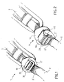
- Fig. 1 illustrates an overall perspective view of the buckle according to the invention in a first configuration of use
- Fig. 2 illustrates an overall perspective view of the buckle according to the invention in a second configuration
- Fig. 3 illustrates an overall perspective view of the buckle according to the invention in a third engagement configuration
- Fig. 4 illustrates a longitudinal sectional view of the buckle according to the invention in a configuration similar to that of Fig. 1;
- Fig. 5 illustrates a longitudinal sectional view of the buckle according to the invention in a configuration similar to that of Fig. 2;
- Fig. 6 illustrates a longitudinal sectional view of the buckle according to the invention in a configuration similar to that of Fig. 3;
- Fig. 7.a illustrates a plan view of a mask comprised in the buckle according to the invention
- Fig. 7.b illustrates a plan view of a plate and mask comprised in the buckle according to the invention
- Fig. 7.b illustrates a plan view of a plaque comprised in the buckle according to the invention.
- a fastening buckle for two ends of belt 2 has been generally designated with 1.
- First and second ends will be designated below with 2' and 2", respectively. These numerals will be used without requiring to establish whether 2' and 2" are two ends of the same belt to be looped or rather two ends of two different belts to be fastened to each other. This difference is, in fact, completely insignificant to the purposes of the present invention.
- the buckle 1 comprises a plate 10 on which there are obtained a slot 11 and a fixing system 12, which is known per se, to a first end 2' of the belt 2.
- FIG. 7.b An exemplary plate 10 comprising a fixing system 12 is represented in Fig. 7.b.
- the fixing system 12 is a simple slit 120, through which the end 2' of the belt 2 is passed, folded and finally stitched such that the plate 10 is definitely fastened in position along the belt 2.
- the fixing system 12 is of the type allowing adjusting the position of the plate 10 along the belt 2.
- the fixing system 12 is of the type allowing a quick adjustment of the position of the plate 10 along the belt 2.
- the fixing system 12 allows the plate 10 to slide smoothly along the belt 2 in the direction required for adjusting the belt 2 to the desired length, while it effectively counteracts the sliding movement in the opposite direction when the belt 2 is tensioned.
- FIG. 7.b An exemplary plate 10 comprising a slot 11 is represented in Fig. 7.b.
- the aperture 110 of the slot 11 defines a first opening 111 which has an available length A.
- the buckle 1 further comprises a mask 30 movable between a first position in which it allows the slot 11 to be completely accessed and a second position in which, on the contrary, it partially restrains the accessibility of the slot 11.
- the mask 30 when the mask 30 is in the second position, it restrains the aperture 110 of the slot 11 such as to define a second opening 112 instead of the first opening 111.
- the second opening 112 has an available length B which is lower than the available length A of the first opening 111.
- the mask 30 is thus substantially C-shaped, and thus has a closed side 301, two tabs 306 and an open side 302.
- the mask 30 comprises fastening means 303 allowing the same to be freely rotated about an axis R-R proximate to the closed side 301.
- the fastening means 303 comprise a single slit 304 for a belt 2 to pass therethrough. Thereby, the mask 30 is fastened by the belt relative to any movement, the only exception being the rotation about the axis R-R.
- an aperture 310 being defined by the two tabs 306.
- the aperture 310 has such a size as to define the second opening 112 on the slot 11 of the plate 10.
- the available length C of the aperture 310 is substantially equal to the available length B of the second opening 112.
- the buckle 1 finally comprises a plaque 20 having a fixing system 22, known per se, to be applied to a second end 2" of the buckle 2.
- the plaque 20 due to its shape and size, is suitable to pass through the slot 11 only when it adopts a particular predetermined engagement position relative to the plate 10.
- the plaque 20 has a length D that is slightly lower than the available length A of the first opening 111 and greater than the available length B of the second opening 112. Due to this size, the plaque 20 can pass through the first opening 111 of the slot 11 by being arranged (see Fig. 3 and 6, for example) in the engagement position relative to the plate 10, i.e. by arranging the same edgeways to the plate 10.
- the fixing system 22 is of the type allowing a quick adjustment of the position of the plaque 20 along the belt 2.
- a fixing system 22 of this type is embodied by two parallel slits 22, the end 2" of the belt 2 being sequentially caused to pass therethrough.
- a smooth sliding of the plaque 20 along the belt 2 is thereby obtained in the step of adjusting the belt 2 to the desired length, i.e. when the belt is at rest.
- the tension acts as the force clamping the belt 2 to the plaque 20 due to the arrangement in the two slits 220, thus effectively counteracting the sliding movement in the opposite release direction.
- the plate 10, the mask 30 and the plaque 20 are arranged on the belt 2 such as described below.
- the first end 2' is connected to the plate 10 by means of the fixing system 12 as described above.
- the mask 30 is also connected to the first end 2' by means of the fastening means 303 as described above.
- the mask 30 can thus rotate along the axis R-R such as schematically represented in Fig. 5 and 6. Particularly, in accordance with the embodiment illustrated, the mask 30 rotates such as to pass from a first position partially raised from the plate 10 (represented in Fig. 3 and 6) to a second abutment position against the latter (represented in Fig. 1 and 4).
- the aperture 110 of the slot 11 is completely accessible, such as to define the first opening 111.
- the mask 30 adopts the second abutment position against the plate 10 by rotating about the axis R-R, the tabs 306 and possibly a part of the closed side 301 partially cover the aperture 110 of the slot 11 such as to restrain the accessibility thereof. Simultaneously, the aperture 310 of the mask 30 at least partially overlaps to the aperture 110 of the slot 11 such as to define the second opening 112.
- the second end 2" is connected to the plaque 20 by means of the fixing system 22 as described above.
- the first step is placing the mask 30 in the first position, which ensures that the slot 11 is completely accessible;
- the second step is placing the plaque 20 in the engagement position, which allows the same to pass through the slot 11;
- the third step is causing the plaque 20 and the second end 2" to pass through the slot 11;
- the fourth step is placing the mask 30 in the second position, which prevents the slot 11 from being completely accessible;
- the fifth step is placing the plaque 20 in the position of use as provided for using the belt 2.
- the method of using the buckle 1 as described above comprises the following steps:
- the first step is placing the mask 30 in a partially raised position from the plate 10, which position allows the first opening 111 to be completely accessible;
- the second step is placing the plaque 20 in the engagement position edgeways relative to the plate 10 (see Fig. 3 and 6) ;
- the third step is causing the plaque 20 and the second end 2" to pass through the first opening 111 of the slot 11;
- the fourth step is placing the mask 30 in an abutment position against the plate 10, in which position the mask 30 at least partially closes the aperture 110 of the slot 11 and leaves the second opening 112 accessible.
- the fifth step is placing the plaque 20 in the position of use abutted against the surface formed by the plate 10 and the mask 30. In this position of use, the second end 2" is arranged through the second opening 112.
- the available length B and the width of the second opening 112 are such that the belt 2 remains snugly housed therein.
- a further step provides the plate 10 sliding along the first end 2' and/or the plaque 20 along the second end 2", such that the length of the belt 2 is adapted to the particular requirements.
- the available length B and the width of the second opening 112 are such that the belt 2 can smoothly slide therethrough during the length adjustment step.
- the second end 2" is provided with an end stop 25 at the end 222" thereof.
- This end stop 25 ensures that the second end 2" will not inadvertedly come off the fixing system 22 when the latter, as described above, provides that the plaque 20 may slide along the belt 2.
- the end stop 25 further comprises an obstacle 250 that is of such a size that it cannot pass through the slot 11, regardless of the position adopted by the mask 30.
- the provision of the obstacle 250 prevents that the user may wrongly arrange the tip 222" of the end 2" through the slot 11. This wrong arrangement is potentially very dangerous, because it will compromise the effectiveness of the clamping force to the plaque 20 as resulting from the belt tensioning. If this clamping is not effective, the plaque 20 will slide along the belt 2 when the latter is tensioned. This sliding will result in the belt 2 being released.
Landscapes
- Buckles (AREA)
Abstract
The object of the present invention is a buckle (1) for a belt. First, the buckle comprises a plate (10) having a slot (11) and a system (12) suitable to be fixed to the first end (2') of a belt (2). The buckle further comprises a plaque (20) having a system (22) suitable to be fixed to the second end (2") of a belt (2). The plaque (20) is suitable to adopt an engagement position, in which the same is allowed to pass through the slot (11) and a position of use. The buckle further comprises a mask (30) movable between a first position in which it allows the slot (11) to be completely accessible and a second position in which it partially restrains the accessibility of the slot (11).
Description
- . The object of the present invention is a buckle for attaching the ends of two belts or two ends of a belt to each other.
- . Buckles for attaching belts are used, for example, in the field of harnesses for sports such as climbing, which consist of a plate comprising a slot fixed to an end and a plaque fixed to the other end which substantially acts as a button.
- . In fact, during the step of fixing this known buckle, the user arranges the plaque in a suitable relative position with respect to the plate. This relative position allows the plaque to pass through the slot formed in the plate. When the plaque has passed through the slot, it is arranged by the user in the position of use as provided for the step of employing the belt. In this position, due to its size, the plaque cannot pass through the slot formed in the plate in the reverse direction, thereby the connection between the two ends is maintained upon use.
- . On the other hand, during the step of unfastening this known buckle, the user arranges the plaque back to the suitable relative position in which it can pass through the slot formed in the plate, thereby the belt ends can be released when use has ceased.
- . These known buckles allow carrying out the fastening and unfastening steps in a comfortable and quick manner. Furthermore, these known buckles allow for a quick adjustment of the belt available length. In view of the above, these buckles are very appreciated, mainly in the climbing field.
- . The buckle described above, however, has considerable drawbacks. In many applications of this type of buckle, typically when it is used in the climbing field, it is not possible to ensure in advance that the belt ends and the buckle parts will stand steady relative to each other throughout use.
- . On the contrary, however, the user (and also the belts and buckle) often has to make and adopt positions, which are quite unpredictable, or may experience fast accelerations in random directions. In these conditions, nothing prevents that parts of the buckle may move relative to each other, and the plaque may inadvertedly adopt the position in which the same is allowed to pass through the slot formed in the plate.
- . It is clearly understood that this event, although it may be considered as improbable, must be however absolutely avoided. This event, in fact, will be a serious danger for the safety of the climber, and often for everyone on the rope.
- . The object of the present invention is to provide a buckle for attaching belt ends, which has such structural and functional characteristics to overcome the drawbacks mentioned with reference to the prior art.
- . The task of the present invention is further to meet the requirements of comfort and usage convenience as discussed above with reference to the prior art.
- . This object and this task are achieved by means of a buckle for attaching belt ends in accordance with claim 1. The dependent claims relate to further aspects or embodiments of the invention.
- . Further characteristics and the advantages of the buckle according to the invention will be apparent from the description below of several preferred embodiments thereof, which are merely illustrative and non-limiting, with reference to the annexed figures, in which:
- . Fig. 1 illustrates an overall perspective view of the buckle according to the invention in a first configuration of use;
- . Fig. 2 illustrates an overall perspective view of the buckle according to the invention in a second configuration;
- . Fig. 3 illustrates an overall perspective view of the buckle according to the invention in a third engagement configuration;
- . Fig. 4 illustrates a longitudinal sectional view of the buckle according to the invention in a configuration similar to that of Fig. 1;
- . Fig. 5 illustrates a longitudinal sectional view of the buckle according to the invention in a configuration similar to that of Fig. 2;
- . Fig. 6 illustrates a longitudinal sectional view of the buckle according to the invention in a configuration similar to that of Fig. 3;
- . Fig. 7.a illustrates a plan view of a mask comprised in the buckle according to the invention;
- . Fig. 7.b illustrates a plan view of a plate and mask comprised in the buckle according to the invention;
- . Fig. 7.b illustrates a plan view of a plaque comprised in the buckle according to the invention.
- . With reference to said figures, a fastening buckle for two ends of
belt 2 has been generally designated with 1. - . First and second ends will be designated below with 2' and 2", respectively. These numerals will be used without requiring to establish whether 2' and 2" are two ends of the same belt to be looped or rather two ends of two different belts to be fastened to each other. This difference is, in fact, completely insignificant to the purposes of the present invention.
- . The buckle 1 comprises a
plate 10 on which there are obtained aslot 11 and afixing system 12, which is known per se, to a first end 2' of thebelt 2. - . An
exemplary plate 10 comprising afixing system 12 is represented in Fig. 7.b. In accordance with this embodiment, thefixing system 12 is asimple slit 120, through which the end 2' of thebelt 2 is passed, folded and finally stitched such that theplate 10 is definitely fastened in position along thebelt 2. - . In accordance with another embodiment, the
fixing system 12 is of the type allowing adjusting the position of theplate 10 along thebelt 2. - . In accordance with a further embodiment, the fixing
system 12 is of the type allowing a quick adjustment of the position of theplate 10 along thebelt 2. In other words, the fixingsystem 12 allows theplate 10 to slide smoothly along thebelt 2 in the direction required for adjusting thebelt 2 to the desired length, while it effectively counteracts the sliding movement in the opposite direction when thebelt 2 is tensioned. - . An
exemplary plate 10 comprising aslot 11 is represented in Fig. 7.b. In accordance with this embodiment, theaperture 110 of theslot 11 defines afirst opening 111 which has an available length A. - . The buckle 1 further comprises a
mask 30 movable between a first position in which it allows theslot 11 to be completely accessed and a second position in which, on the contrary, it partially restrains the accessibility of theslot 11. - . More particularly, when the
mask 30 is in the second position, it restrains theaperture 110 of theslot 11 such as to define asecond opening 112 instead of thefirst opening 111. Thesecond opening 112 has an available length B which is lower than the available length A of thefirst opening 111. - . In accordance with the embodiment as illustrated in Fig. 7.a, the
mask 30 is thus substantially C-shaped, and thus has aclosed side 301, twotabs 306 and an open side 302. - . The
mask 30 comprises fastening means 303 allowing the same to be freely rotated about an axis R-R proximate to theclosed side 301. The fastening means 303 comprise asingle slit 304 for abelt 2 to pass therethrough. Thereby, themask 30 is fastened by the belt relative to any movement, the only exception being the rotation about the axis R-R. - . On the other hand, on the open side 302 of the
mask 30 there is formed anaperture 310 being defined by the twotabs 306. Theaperture 310 has such a size as to define thesecond opening 112 on theslot 11 of theplate 10. Particularly, the available length C of theaperture 310 is substantially equal to the available length B of thesecond opening 112. - . The buckle 1 finally comprises a
plaque 20 having a fixingsystem 22, known per se, to be applied to asecond end 2" of thebuckle 2. Theplaque 20, due to its shape and size, is suitable to pass through theslot 11 only when it adopts a particular predetermined engagement position relative to theplate 10. - . In accordance with the embodiment of the invention as represented in Fig. 7.c., the
plaque 20 has a length D that is slightly lower than the available length A of thefirst opening 111 and greater than the available length B of thesecond opening 112. Due to this size, theplaque 20 can pass through thefirst opening 111 of theslot 11 by being arranged (see Fig. 3 and 6, for example) in the engagement position relative to theplate 10, i.e. by arranging the same edgeways to theplate 10. - . In accordance again with the embodiment as represented in Fig. 7.c., the fixing
system 22 is of the type allowing a quick adjustment of the position of theplaque 20 along thebelt 2. - . A fixing
system 22 of this type is embodied by twoparallel slits 22, theend 2" of thebelt 2 being sequentially caused to pass therethrough. A smooth sliding of theplaque 20 along thebelt 2 is thereby obtained in the step of adjusting thebelt 2 to the desired length, i.e. when the belt is at rest. On the other hand, when the belt is tensioned, the tension acts as the force clamping thebelt 2 to theplaque 20 due to the arrangement in the twoslits 220, thus effectively counteracting the sliding movement in the opposite release direction. - . In accordance with an embodiment of the invention, the
plate 10, themask 30 and theplaque 20 are arranged on thebelt 2 such as described below. - . First, the first end 2' is connected to the
plate 10 by means of the fixingsystem 12 as described above. - . Secondly, the
mask 30 is also connected to the first end 2' by means of the fastening means 303 as described above. - . The
mask 30 can thus rotate along the axis R-R such as schematically represented in Fig. 5 and 6. Particularly, in accordance with the embodiment illustrated, themask 30 rotates such as to pass from a first position partially raised from the plate 10 (represented in Fig. 3 and 6) to a second abutment position against the latter (represented in Fig. 1 and 4). - . When the
mask 30 is in the first position, partially raised from theplate 10, theaperture 110 of theslot 11 is completely accessible, such as to define thefirst opening 111. - . On the contrary, when the
mask 30 adopts the second abutment position against theplate 10 by rotating about the axis R-R, thetabs 306 and possibly a part of theclosed side 301 partially cover theaperture 110 of theslot 11 such as to restrain the accessibility thereof. Simultaneously, theaperture 310 of themask 30 at least partially overlaps to theaperture 110 of theslot 11 such as to define thesecond opening 112. - . Third, the
second end 2" is connected to theplaque 20 by means of the fixingsystem 22 as described above. - . A preferred method of use for the buckle 1 according to the invention is described below by steps:
- . The first step is placing the
mask 30 in the first position, which ensures that theslot 11 is completely accessible; - . The second step is placing the
plaque 20 in the engagement position, which allows the same to pass through theslot 11; - . The third step is causing the
plaque 20 and thesecond end 2" to pass through theslot 11; - . The fourth step is placing the
mask 30 in the second position, which prevents theslot 11 from being completely accessible; - . The fifth step is placing the
plaque 20 in the position of use as provided for using thebelt 2. - . For example, with reference to the embodiment of the invention as represented in the annexed figures, the method of using the buckle 1 as described above comprises the following steps:
- . The first step is placing the
mask 30 in a partially raised position from theplate 10, which position allows thefirst opening 111 to be completely accessible; - . The second step is placing the
plaque 20 in the engagement position edgeways relative to the plate 10 (see Fig. 3 and 6) ; - . The third step is causing the
plaque 20 and thesecond end 2" to pass through thefirst opening 111 of theslot 11; - . The fourth step, for example, is placing the
mask 30 in an abutment position against theplate 10, in which position themask 30 at least partially closes theaperture 110 of theslot 11 and leaves thesecond opening 112 accessible. - . The fifth step is placing the
plaque 20 in the position of use abutted against the surface formed by theplate 10 and themask 30. In this position of use, thesecond end 2" is arranged through thesecond opening 112. The available length B and the width of thesecond opening 112 are such that thebelt 2 remains snugly housed therein. - . In accordance with an embodiment of the method, a further step provides the
plate 10 sliding along the first end 2' and/or theplaque 20 along thesecond end 2", such that the length of thebelt 2 is adapted to the particular requirements. - . The available length B and the width of the
second opening 112 are such that thebelt 2 can smoothly slide therethrough during the length adjustment step. - . In accordance with an embodiment of the invention, the
second end 2" is provided with anend stop 25 at theend 222" thereof. Thisend stop 25 ensures that thesecond end 2" will not inadvertedly come off the fixingsystem 22 when the latter, as described above, provides that theplaque 20 may slide along thebelt 2. - . In accordance with a further embodiment, the
end stop 25 further comprises anobstacle 250 that is of such a size that it cannot pass through theslot 11, regardless of the position adopted by themask 30. - . The provision of the
obstacle 250 prevents that the user may wrongly arrange thetip 222" of theend 2" through theslot 11. This wrong arrangement is potentially very dangerous, because it will compromise the effectiveness of the clamping force to theplaque 20 as resulting from the belt tensioning. If this clamping is not effective, theplaque 20 will slide along thebelt 2 when the latter is tensioned. This sliding will result in thebelt 2 being released. - . From what has been stated above, it is clearly understood that any arrangement of the
obstacle 250 on theend stop 25 will result in additional safety for the user. - . To the preferred embodiment of the buckle as described above, those skilled in the art, aiming at satisfying contingent and specific requirements, may carry out a number of modifications, adaptations and replacements of elements with functionally equivalent ones, without however departing form the scope of the claims below.
Claims (16)
- A buckle (1) for a belt comprising:- a plate (10) having a slot (11) and a system (12) suitable to be fixed to a first end (2') of a belt (2); and- a plaque (20) having a system (22) suitable to be fixed to a second end (2") of a belt, said plaque (20) being suitable to adopt an engagement position in which the same is allowed to pass through said slot (11), and a position of use;wherein said buckle further comprises a mask (30) movable between a first position in which it allows said slot (11) to be completely accessible and a second position in which, on the contrary, it partially restrains the accessibility of said slot (11).
- The buckle (1) according to claim 1, wherein said slot (11) defines a first opening (111), said plaque (20) being suitable to pass through said first opening (111) in said engagement position.
- The buckle (1) according to claim 2, wherein said mask (30) in said second position at least partially obstructs said slot (11) such as to define a second opening (112), said plaque (20) being unsuitable to pass through said second opening (112).
- The buckle (1) according to claim 2, wherein said first opening (111) has a length A greater than the available length B of said second opening (112).
- The buckle (1) according to claim 4 wherein said plaque (20) has an available length D greater than the available length B of said second opening (112) and lower than the available length A of said first opening (111), respectively.
- The buckle (1) according to claim 3, wherein said mask (30) comprises an aperture (310) suitable to overlap, at least partially, to said slot (11) such as to define said second opening (112).
- The buckle (1) according to any preceding claim,
wherein said system (12) for fixing said plate (10) to said belt (2) is of a type allowing the adjustment of the position of said plate (10) along said belt (2). - The buckle (1) according to any preceding claim,
wherein said system (22) for fixing said plaque (20) to said belt (2) is of a type allowing the adjustment of the position of said plaque (20) along said belt (2). - The buckle (1) according to claim 1, wherein said second end (2") comprises an end stop (25) having such a size as to prevent the tip (222") of said second end (2") from passing through said fixing system (22).
- The buckle (1) according to claim 1, wherein said second end (2") comprises an obstacle (250) having a larger size than said slot (11) such as to prevent the tip (222") of said second end (2") from passing through said slot (11).
- A method for using a buckle in accordance with claim 1, comprising the following steps:- placing said mask (30) in said first position such as to ensure that said slot (11) is completely accessible;- placing said plaque (20) in said engagement position such as to allow the passage through said slot (11) ;- passing said plaque (20) and said second end (2") through said slot (11);- placing said mask (30) in said second position such as to prevent said slot (11) from being completely accessible;- placing said plaque (20) in said position of use.
- The method according to claim 12, wherein said step of placing said mask (30) in said first position comprises the step of partially rotating said mask (30) relative to said plate (10) such as to be partially raised therefrom.
- The method according to claim 12, wherein said step of placing said plaque (20) in said engagement position comprises the step of placing said plaque (20) edgeways relative to said plate (10).
- The method according to claim 12, wherein said step of placing said mask (30) in said second position comprises the step of rotating said mask (30) such as to bring the latter into abutment against said plate (10).
- The method according to claim 12, wherein said step of placing said plaque (20) in said position of use comprises the step of abutting said plaque (20) against a surface formed by said plate (10) and said mask (30).
- The method according to any claim 12 to 16, comprising as a further step the plate (10) sliding along said first end (2') and/or the plaque (20) sliding along said second end (2") such as to adjust the length of said belt (2).
Applications Claiming Priority (1)
| Application Number | Priority Date | Filing Date | Title |
|---|---|---|---|
| IT000565A ITMI20050565A1 (en) | 2005-04-05 | 2005-04-05 | BUCKLE FOR A BELT |
Publications (1)
| Publication Number | Publication Date |
|---|---|
| EP1709882A2 true EP1709882A2 (en) | 2006-10-11 |
Family
ID=36615669
Family Applications (1)
| Application Number | Title | Priority Date | Filing Date |
|---|---|---|---|
| EP06425233A Withdrawn EP1709882A2 (en) | 2005-04-05 | 2006-04-04 | Buckle for a belt |
Country Status (2)
| Country | Link |
|---|---|
| EP (1) | EP1709882A2 (en) |
| IT (1) | ITMI20050565A1 (en) |
Cited By (6)
| Publication number | Priority date | Publication date | Assignee | Title |
|---|---|---|---|---|
| FR2927232A1 (en) * | 2008-02-12 | 2009-08-14 | Sperian Fall Prot France Soc P | Belt clasp for harness used during hill-climbing, has plating unit arranged for plating portion of superimposed sections of strap on male element, where male element is intended to cooperate with antagonist female element |
| RU2462970C1 (en) * | 2011-05-06 | 2012-10-10 | Виктор Владимирович Зайцев | Detachable mounting unit (versions) and method of its production (versions) |
| DE202012104267U1 (en) | 2012-11-07 | 2013-02-11 | Karin Böhme | Gürtelschließe |
| ITMI20131270A1 (en) * | 2013-07-29 | 2015-01-30 | Camp Spa | BELT BUCKLE |
| EP2946682A1 (en) * | 2014-05-22 | 2015-11-25 | Oberalp Spa | Closing assembly and outdoor security belt assembly |
| WO2020185650A1 (en) * | 2019-03-11 | 2020-09-17 | Falvai Mark | Flexible couple system and methods of operation |
Families Citing this family (1)
| Publication number | Priority date | Publication date | Assignee | Title |
|---|---|---|---|---|
| ITMI20050633A1 (en) | 2005-04-13 | 2006-10-14 | Camp Spa | HARNESS |
-
2005
- 2005-04-05 IT IT000565A patent/ITMI20050565A1/en unknown
-
2006
- 2006-04-04 EP EP06425233A patent/EP1709882A2/en not_active Withdrawn
Cited By (6)
| Publication number | Priority date | Publication date | Assignee | Title |
|---|---|---|---|---|
| FR2927232A1 (en) * | 2008-02-12 | 2009-08-14 | Sperian Fall Prot France Soc P | Belt clasp for harness used during hill-climbing, has plating unit arranged for plating portion of superimposed sections of strap on male element, where male element is intended to cooperate with antagonist female element |
| RU2462970C1 (en) * | 2011-05-06 | 2012-10-10 | Виктор Владимирович Зайцев | Detachable mounting unit (versions) and method of its production (versions) |
| DE202012104267U1 (en) | 2012-11-07 | 2013-02-11 | Karin Böhme | Gürtelschließe |
| ITMI20131270A1 (en) * | 2013-07-29 | 2015-01-30 | Camp Spa | BELT BUCKLE |
| EP2946682A1 (en) * | 2014-05-22 | 2015-11-25 | Oberalp Spa | Closing assembly and outdoor security belt assembly |
| WO2020185650A1 (en) * | 2019-03-11 | 2020-09-17 | Falvai Mark | Flexible couple system and methods of operation |
Also Published As
| Publication number | Publication date |
|---|---|
| ITMI20050565A1 (en) | 2006-10-06 |
Similar Documents
| Publication | Publication Date | Title |
|---|---|---|
| KR100278338B1 (en) | Protective head protection assembly for human | |
| US9155359B1 (en) | Ratchet buckle with locking mechanism | |
| US7506413B2 (en) | Web position adjusting device | |
| US5031962A (en) | Low profile web adjuster | |
| CA2038505C (en) | Low profile web adjuster | |
| US9179729B2 (en) | Tightening systems | |
| EP2983542B1 (en) | Clamping device | |
| US8967332B2 (en) | Safety harness strap adjuster | |
| CN104519840B (en) | For fixing the orthopedic instruments of shoulder joint | |
| DE10004819A1 (en) | Seat belt system | |
| EP2736607A2 (en) | Strap adjuster and keeper and method of strap control | |
| US9861849B2 (en) | Fastening system for a sports and recreational facility | |
| EP1709882A2 (en) | Buckle for a belt | |
| CN105658104A (en) | Self-acting webbing adjuster and helmet strap system including said adjuster | |
| DE9104917U1 (en) | Belt tensioner for a seat belt in a vehicle | |
| US6860566B2 (en) | Harnesses and inertia reels | |
| RU2535660C2 (en) | Method and device for adjustment of protective belt strap | |
| US12239859B2 (en) | Ratcheting strap adjuster | |
| CN222218558U (en) | Cam clamping device | |
| EP1956934B1 (en) | Belt and buckle for a belt | |
| EP4018867B1 (en) | Boot comprising a device for adjusting the closure of the leg portion | |
| WO2005080149A1 (en) | Restraint means | |
| KR100412442B1 (en) | Seat belt tongue assembly | |
| DE8225081U1 (en) | Hard hat with a chin strap | |
| DE102011002576B4 (en) | Device for adjustable attachment of a headgear |
Legal Events
| Date | Code | Title | Description |
|---|---|---|---|
| PUAI | Public reference made under article 153(3) epc to a published international application that has entered the european phase |
Free format text: ORIGINAL CODE: 0009012 |
|
| AK | Designated contracting states |
Kind code of ref document: A2 Designated state(s): AT BE BG CH CY CZ DE DK EE ES FI FR GB GR HU IE IS IT LI LT LU LV MC NL PL PT RO SE SI SK TR |
|
| AX | Request for extension of the european patent |
Extension state: AL BA HR MK YU |
|
| STAA | Information on the status of an ep patent application or granted ep patent |
Free format text: STATUS: THE APPLICATION IS DEEMED TO BE WITHDRAWN |
|
| 18D | Application deemed to be withdrawn |
Effective date: 20121101 |